HMS Alert SOS Edition by PaulV [COMPLETED BUILD]

Great video (as always)! You are ahead of all us by a large margin, you kinda a pioneer... ;) Here are my questions, I might post at my build log as well. You made a decision to simulate bolts by drilling only chocks. Will you drill the frames outside as well? Also, how about the plain scarphs in the frames: will you simulate bolts\trunnels as well? If yes, what will be the bolting pattern. I am trying to find the correct pattern but no luck thus far. What makes it worth, there are long scarphs (floor timbers with the second futtock) and short scarphs (second futtock with lengthening piece). it should be 2 different patterns, though. Any clue???
 
Hi Daniel
Yes the Putty cleans up well. Still not sure if I like the effect, but to late now! We will see what it looks like final wood seal, but that's a looong way away. BTW did notice two templates for Ribs 57 & 56 - Very confusing! considering there is only one rib of eACH.


Jimsky
No I do not intend to do the outside, as it is not apparent that they went all the way through, and none of the models show this. I think I will leave at Chocks and keel joints. If I tried to do all the others, it would look like a poker-dot hull.
I personally prefer just the representation of the major joints only. No that I suspect these will be highly visible afer.

Not that far ahead. I' just doing it Rib set by Rib set. and following the manual as it states. It all fits as its supposed to so far.
 
Hi Paul, I have to agree re the external fastenings and also the polka dot effect.. Some of the major fastenings inside will be quite effective. Cheers, Danw
 
Hi Paul, I have to agree re the external fastenings and also the polka dot effect.. Some of the major fastenings inside will be quite effective. Cheers, Danw
Valid point both Danw and Paul, but...two things: how the fasting laid in the real ship and how we want to represent it in our models. In the Wangs model, he did the scarph bolting. Again, we are willing to build as per our abilities and taste. I am trying to understand the way it was... :cool:
 
Greetings from Brooklyn, Paul! Hope you have a sunny & pleasant day as we do in New York. :) Since you have already completed the Stern section, I am challenging you with a couple of questions hoping you clear the shades. So...the size in relation to all of the parts making the Stern: The 'counter timbers' parts 38 & 40 what is the width should be? The slots are cut with a size of 2.90 ~ 3.1mm. Parts 38\40 are 3.32 ~ 3.38mm. A similar situation with 'wind transom', 'desk transom', and 'helm port transom' (Parts BL30, 31, and 32).
 
Morning Jim from a Rainy Melb.

I did not adjust any of the length of any of the items. they are all correct. The trick is to file out the slots on part BL 31 & 32 correctly. Doing a dry fit, fit parts 38 & 40 first. You will see the 40 are a little longer as they should be. Next remove them and dry fit 31 so that it goes hard against the stern post and fits in the holders. Make sure you have it round the correct way and it should fit. Next remove 31 replace 38 & 40 & glue in place on 30 ( the little notch on the end may have to be cleaned so they fit on and against edge of 30. File the slots for 38/40 on 31 so that it sits over them and fully in its berth holder correctly. A lot of trial and file and trial etc.

It will fit snugly, but there will be some slight gap at the top edge of 31 over 38/40. I wood filled where needed. Next shape 32 a lot so that it fits in its holder completely. This will line up with the sizes of 38/40 and fit properly after sanding the slots for 38/40 on 32( which is why I did the video in opposite order to the manual). It. will all hold together well without glue. Repeat for parts 39/41 for the top. by adjusting the slots in 32. 39/40 have a smaill slot in them so makes ure they go in correctly- slot to rear look at manual image) . Dry fit it all and you see from the rear of the berth looking under it all sits nicely. Now dry fit parts 37 ad they will only need adjusting by beveling to fit. The originally look short, but when it all comes together they fit. Glue and wait till that all dry, then fit and sand the remaining Ribs. It will all fit. The ribs will need to be beveled slightly on the ends to make then sit correctly on 37.

Still dont know whey there are 6 parts 37 in the kit when it only asks for two of them so far.

Its a lot of trial and error dry fitting, dropping shit etc ,but it does come together.

Ask away anytime. I'm about 50% though updating the manual as that's where we all are. Sick of doing Ribs! and the doubles are fragile. 4 per day means another 10 days !
 
Last edited:
Many thanks for the detailed answer. Paul. So... ya saying the slots in the parts 30, 31, and 32 need to be widened to the size of the parts 38 and 40, correct?
 
NO Video Today yet. Milestone Reached: All double ribs now completed. What a Pita some of them where. I think the router bit was dull as board 3 had major burring on all the cuts. Also a lot of the cuts were not deep enough and needed a lot of effort to get out and clean up later.

Still sanding and cleaning ribs ready for installation. A LOT ( all) of mine have the lower cutout to small to fit on the keel risers and do need filing out to fit firmly. Still better than over sized. The template have been sensational and holds the parts hard against each other when drying( yes all parts fit tightly with cling wrap., do not adjust template). They have also saved me issues where I have incorrectly labeled the parts only to find they do not fit in the template. Using the template 'locks' is Very Very important as it strengthens the MDF template and hold the rib parts in well.

The only drawback is although you can fit 4/8 half rib sets on the first gluing, only one per side can fit for the second half ( they overlap on each other and do not sit flat ( you will see when you come to them)

Apart from sore arms & hands, the experience has been fun.

Warning Do not cut out all the Rib parts at once. There are over 300 parts and a lot to loose / mix up. I did it a 'M' template at a time and its still a lot to handle.

NOTE the Chocks are numbered and designed for each rib pair. IF you use the 'correct' ones they fit nicely.

See you in the Video in a couple of days ( 40 Ribs to still clean up)

PS do not forget 57,56 & 20,19,18,17 do not throw away inner template parts as they are use for faring markers.
 
yea...lot's of work, indeed, but...it is part of the fun, packaged along with the kit. But...think about if you are a scratch builder, and have to make 83 frames from scratch...cut, shape, glue more than 300+ pieces. WOW...I cannot imagine doing it without CNC...looking forward to your next video. :cool:
 
A LOT ( all) of mine have the lower cutout to small to fit on the keel risers and do need filing out to fit firmly.
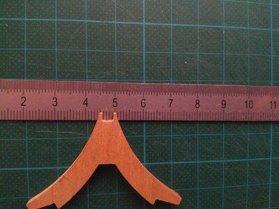
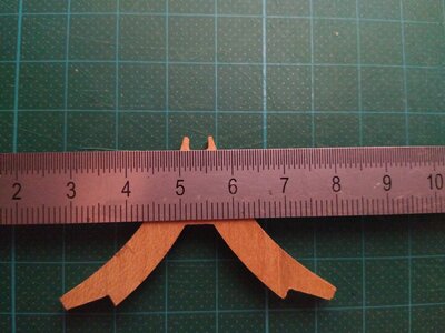
Yes, that's the next "groove-problem" I have too ... working on Rib 57 today I noticed that the cutout was too small again... my main problem here is, the Keel is 5mm thick, the cutout 4 ... if I widen it to 5mm I'll loose almost all of the tips at its sides ... so there will be no more "brackets" holding on the side of the keel ...
IMG_20201011_115740.jpgIMG_20201011_115859.jpg
maybe I should better narrow the Keel?
How will you work that out?
 
... my main problem here is, the Keel is 5mm thick, the cutout 4 ... if I widen it to 5mm I'll loose almost all of the tips at its sides ... so there will be no more "brackets" holding on the side of the keel ...
In the first picture the cutout looks like 3mm not 4mm
The second picture looks like 3.5mm
 
...and when finished it should be 5mm to sit around the Keel ... but at its bottom the part is just a little more than 5mm (5,5 at best), at the base of the cutout it is about 7mm ... so just a littel "nothing" of the bracets that hold it left and right of the keel would be left
That's why I thought/asked if it would be better to narrow the Keel instead.
 
Back
Top