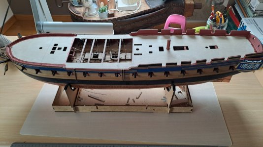
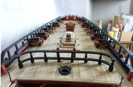
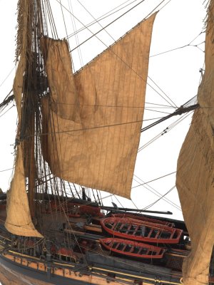
Good morning Marc. Quality work. Bravo. Cheers GrantWell, Allan is right.
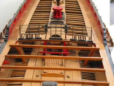
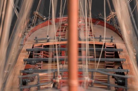
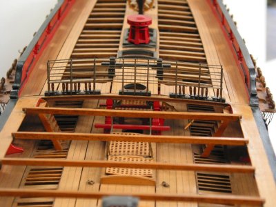
My gratings were not pulling at all. So I took out the old ones (very carefully) and replaced them with the Allan gratings. But, the result is much better!
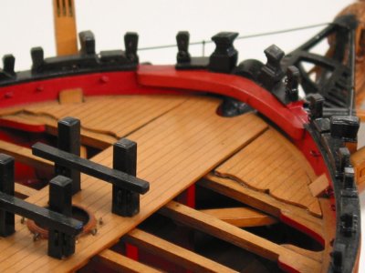
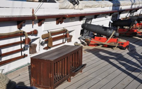
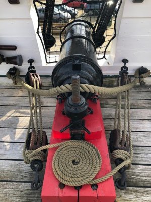
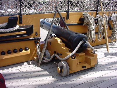
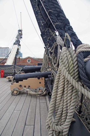
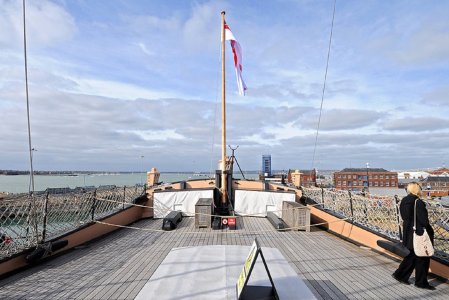
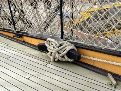
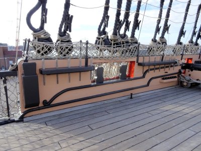
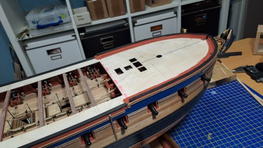
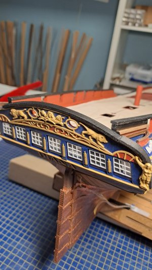
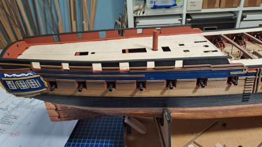
And then the placement of thecables. I made an additional Forward riding bitt as shown on the original Artois class.:
View attachment 487111
View attachment 487103
View attachment 487104
View attachment 487105
View attachment 487106
View attachment 487107
-

Win a Free Custom Engraved Brass Coin!!!
As a way to introduce our brass coins to the community, we will raffle off a free coin during the month of August. Follow link ABOVE for instructions for entering.
-

PRE-ORDER SHIPS IN SCALE TODAY!
The beloved Ships in Scale Magazine is back and charting a new course for 2026!
Discover new skills, new techniques, and new inspirations in every issue.
NOTE THAT OUR FIRST ISSUE WILL BE JAN/FEB 2026
You are using an out of date browser. It may not display this or other websites correctly.
You should upgrade or use an alternative browser.
You should upgrade or use an alternative browser.
HMS Diana by Caldercraft
- Thread starter HMSFly
- Start date
- Watchers 37
-
- Tags
- caldercraft diana
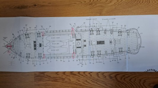
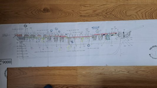
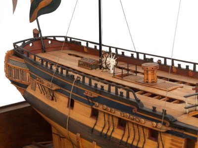
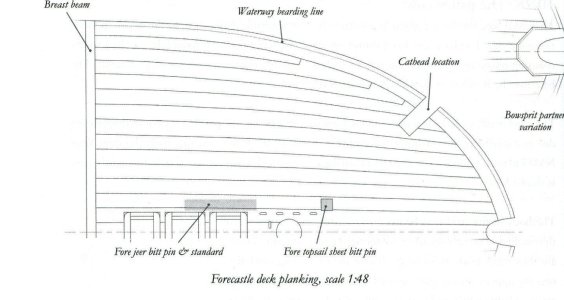
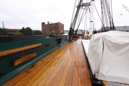
1. There is no waterway.
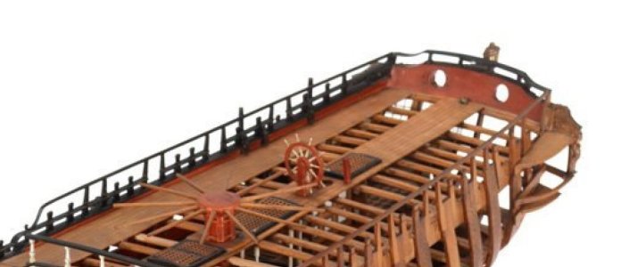
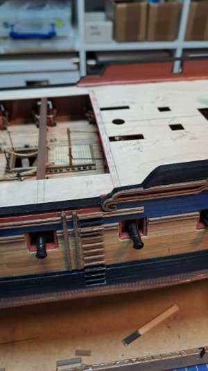
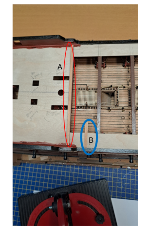
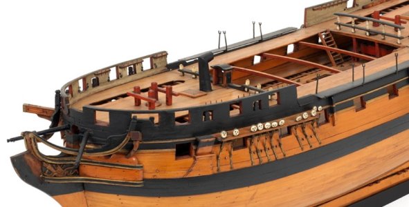
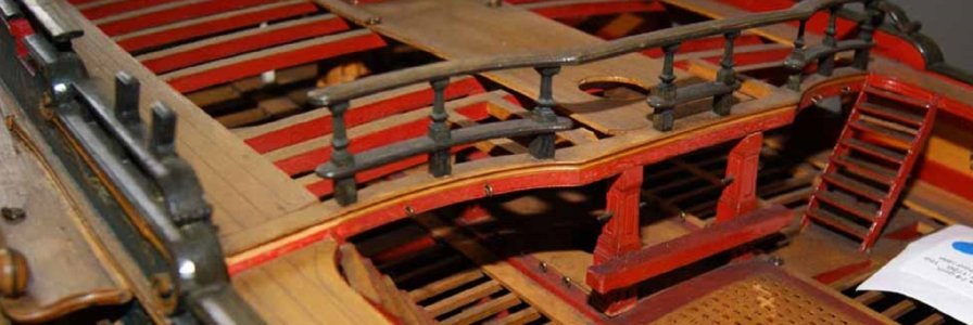
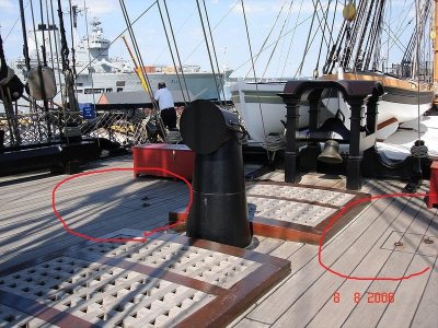
2. The deck flooring should not cover the first beam of the quarterdeck and the last beam of the forecastle. These beams were wider and higher than the others and had a special groove for deck boards. So, these beams were naked.
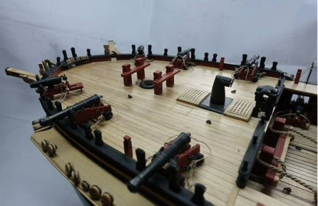
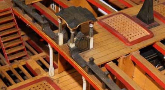
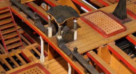
3. There are no cushions for spare topmasts. The pillows were located between the bollards and the bell tower.
And the pillows, and the bollards, and the bell tower stand on the bare beam of the forecastle.
4. Short boards and wood chips instead of long boards are not acceptable. This is a grave mistake. In reality, instead of short chips, they simply lengthened the board.
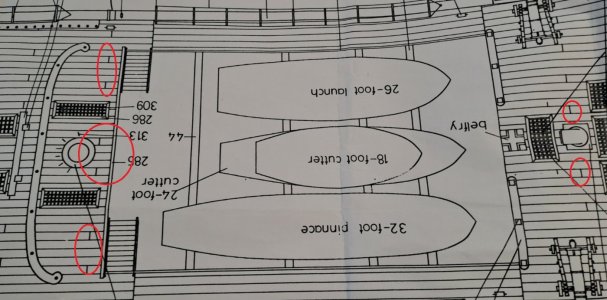
5. Special hatches for rigging near the mast did not have coamings. The gratings were temporary and were installed flush with the deck.
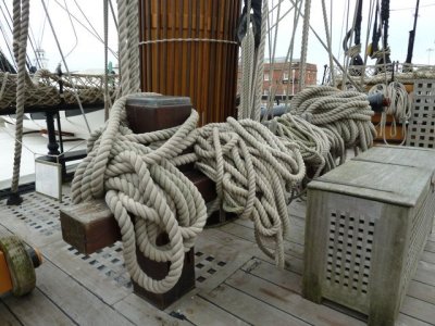
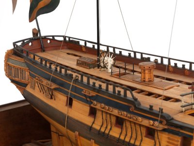
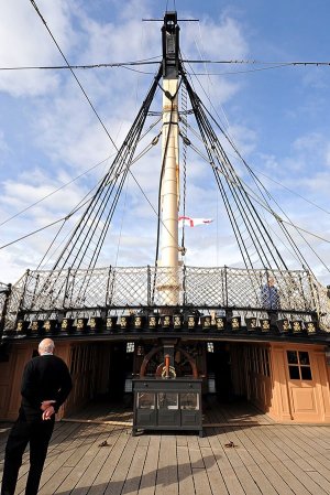
6. Two small hatches behind the mainmast are intended for wiring hoists, with the help of which the main topmast was raised and lowered. They had no coamings, no grilles. The hatches were closed with caps made to fit the deck flooring. (The photo shows such hatches for both the main topmast and the fore topmast on the HMS Victory).
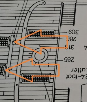
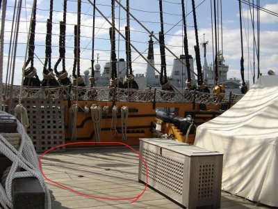
7. In the middle of the deck flooring there was a royal (also known as the admiralty) board. It is one and a half times wider than the others. It was located along the diametrical plane. This royal board was on the battery decks, and on the quarterdeck and forecastle.
2. The deck flooring should not cover the first beam of the quarterdeck and the last beam of the forecastle. These beams were wider and higher than the others and had a special groove for deck boards. So, these beams were naked.

3. There are no cushions for spare topmasts. The pillows were located between the bollards and the bell tower.
And the pillows, and the bollards, and the bell tower stand on the bare beam of the forecastle.

4. Short boards and wood chips instead of long boards are not acceptable. This is a grave mistake. In reality, instead of short chips, they simply lengthened the board.

5. Special hatches for rigging near the mast did not have coamings. The gratings were temporary and were installed flush with the deck.

6. Two small hatches behind the mainmast are intended for wiring hoists, with the help of which the main topmast was raised and lowered. They had no coamings, no grilles. The hatches were closed with caps made to fit the deck flooring. (The photo shows such hatches for both the main topmast and the fore topmast on the HMS Victory).


7. In the middle of the deck flooring there was a royal (also known as the admiralty) board. It is one and a half times wider than the others. It was located along the diametrical plane. This royal board was on the battery decks, and on the quarterdeck and forecastle.

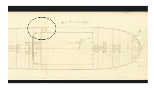
I assume you downloaded all of the free high resolution drawings from the WikiCommons site. If you have, for the scuttles, these are clearly shown on the Artois class FC and QD deck drawings. These drawings will show you the differences from the ship and the kit drawings.
I know this is merely a terminology thing, but when you say the main deck, what are you referring to?. The gun deck is in place so I am guessing you are speaking about the QD or FC which in the case of Diana were connected with the gangways.

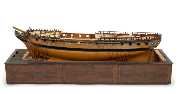
I went back and double checked against other sources and found the contemporary model of Diana (38) 1794 shows only four boatskids and they are NOT evenly spaced.38 gun ships had five fir boatskids according to The Elements and Practice of Naval Architcture

I know this is merely a terminology thing, but when you say the main deck, what are you referring to?. The gun deck is in place so I am guessing you are speaking about the QD or FC which in the case of Diana were connected with the gangways.

Last edited:
Wow, lots of useful info.
first :
Did I understand correctly that no waterway should be placed?
The other questions will come later...

first :
Did I understand correctly that no waterway should be placed?
The other questions will come later...
Dear Iutar and Allan,
I will follow your comments and implement:
- the Waterway
- No Short boards and wood chips instead of long boards are not acceptable: In reality, instead of short chips, they simply lengthened the board. Only the long ones.
- As suggested: Two small hatches behind the mainmast are intended for wiring hoists, with the help of which the main topmast was raised and lowered. They had no coamings, no grilles. The hatches were closed with caps made to fit the deck flooring.
Others if possible, will be continued.
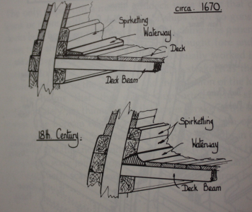
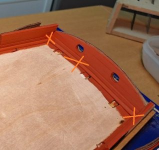
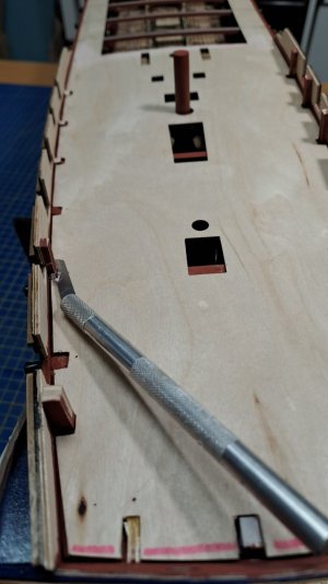
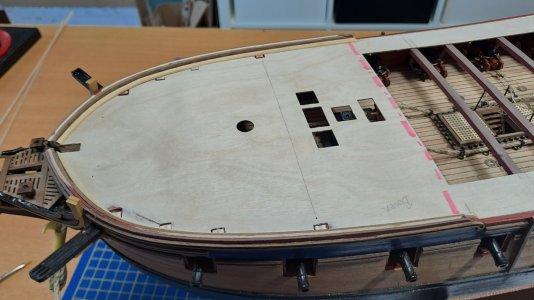
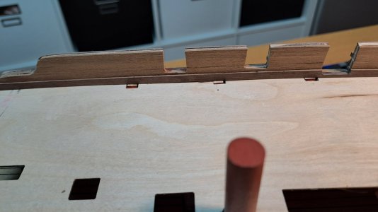
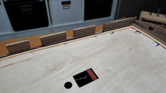
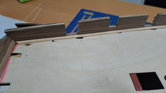
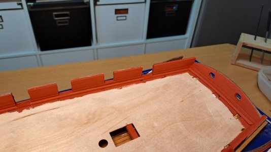
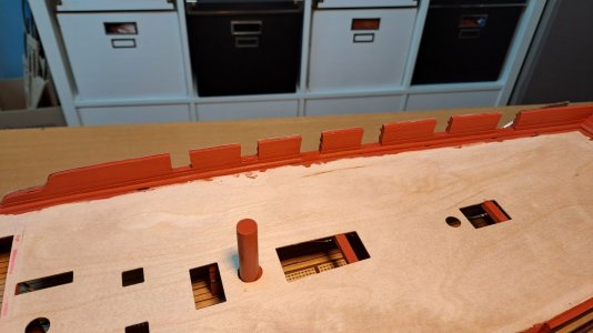
1- The Waterway:
I first installed a 2 x 4 mm Walnut as Spirketling
Followed by 1 x 4 mm strips to the top ...
Last but not least I used a 2 x 2 mm strip, which I have beveled (+- 45°) as the Waterway shown on the picture.
This whas the most difficult one, because the size of 2 x 2 mm.
And I painted it red-occre...
See pictures: Ok ?
Cheers
Marc


Sear Iutar,
I'm sorry but I interpreted the photo as if there was indeed a waterway.It' confusing: on the first photo is saw an waterway, on the second model not...
There are very big differences depending on who did it.
I just finished the USS Constitution and there was a watership there, a ship from the same period....
I really appreciate your comments and will take them into account...watch and see...
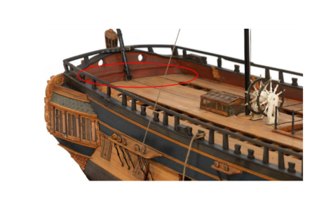

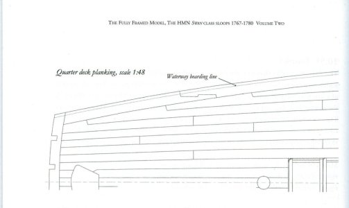
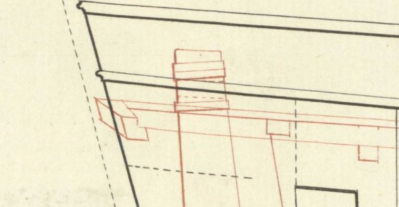
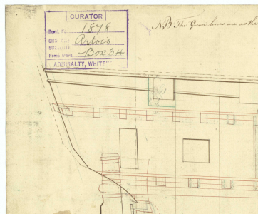
No need to apologize. After I spent some time looking at additional contemporary models it would be very easy to misinterpret as you did and I am sure you are not the first nor will you be the last. The easiest way to avoid these little errors is to study the contemporary drawings as you move along on the build and ignore the kit instructions if you find an error. The inboard profile drawing for example is very useful. The QD beam and planking can be seen in the drawing of the Diana and Artois below which is similar to the one shown above by Iutar.I interpreted the photo as if there was indeed a waterway.
Hi Allan,
Thanks for your encouraging words. I think it's important to always stay positive, even when you get (constructive) criticism.
So we continue...
Thanks for your encouraging words. I think it's important to always stay positive, even when you get (constructive) criticism.
So we continue...
The QD planks rest on the forward most beam which is wide enough to also support the end of the gangway planks if they are on the same level, but is there also a cover board that goes over the forward ends of the QD deck planks? That is what the photo of the model at Preble Hall looks like but it is not too clear.
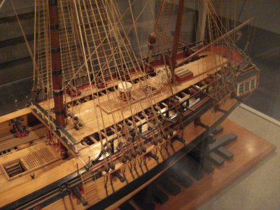

Dear HMS Fly! Bare beams on the edges of the forecastle and quarterdeck existed until the twenties of the nineteenth century. So don't worry.
View attachment 488423
View attachment 488426
View attachment 488427
Please don't forget the cushions for the spare wood.
View attachment 488430
View attachment 488431


