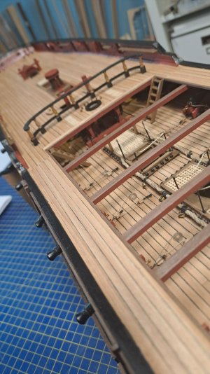
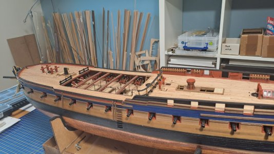
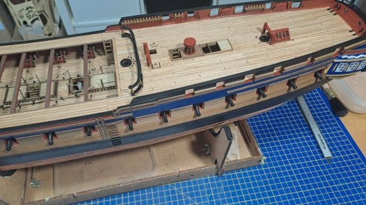
Good morning Marc. I have learned plenty from the input of Allan and Iutar while reading through the past few pages. Wow you are building a quality Diana. Kudos. Cheers Grant
-

Win a Free Custom Engraved Brass Coin!!!
As a way to introduce our brass coins to the community, we will raffle off a free coin during the month of August. Follow link ABOVE for instructions for entering.
-

PRE-ORDER SHIPS IN SCALE TODAY!
The beloved Ships in Scale Magazine is back and charting a new course for 2026!
Discover new skills, new techniques, and new inspirations in every issue.
NOTE THAT OUR FIRST ISSUE WILL BE JAN/FEB 2026
You are using an out of date browser. It may not display this or other websites correctly.
You should upgrade or use an alternative browser.
You should upgrade or use an alternative browser.
HMS Diana by Caldercraft
- Thread starter HMSFly
- Start date
- Watchers 37
-
- Tags
- caldercraft diana
Hello Grant,Good morning Marc. I have learned plenty from the input of Allan and Iutar while reading through the past few pages. Wow you are building a quality Diana. Kudos. Cheers Grant
Thank you very much!
Yes, I learned a lot too.
As a matter of fact I should have actually bought the book "The Frigate Diana (Anatomy of the Ship) Hardcover – January 1, 2004
by David White (Author)"..but 145 US $ Is rather expensive...
Next time for the next ship.....
It likely had one, but if you are not rigging the model with sails set for sea there are a lot of contemporary models that do not show the binnacle. As it was tied down with rope rather being a permanent fixture perhaps it was stowed with the spare binnacle and compasses that were kept stored below when not at sea. Either way, you would not be the first to leave it off.
Allan
Allan
The "Anatomy of the Ship" book by David White concerning Diana does not show a binnacle anywhere in the plans. Since I'm currently building this very same Caldercraft/Jotika model, I don't understand why a heavy frigate such as this would not have a binnacle in the very empty space between the wheel and the slightly trapezoidal hatch.
Hello,The "Anatomy of the Ship" book by David White concerning Diana does not show a binnacle anywhere in the plans. Since I'm currently building this very same Caldercraft/Jotika model, I don't understand why a heavy frigate such as this would not have a binnacle in the very empty space between the wheel and the slightly trapezoidal hatch.
Interesting: you are building the same ship/kit...
I hope my comments are useful to you..(and I hope my questions are relevant)...
How far along are you in your construction project?
PS
I'm going to build the Binnacle & Compass...I hope I find the right dimensions either in 1/64 or the real dimensions
Hi Marc,
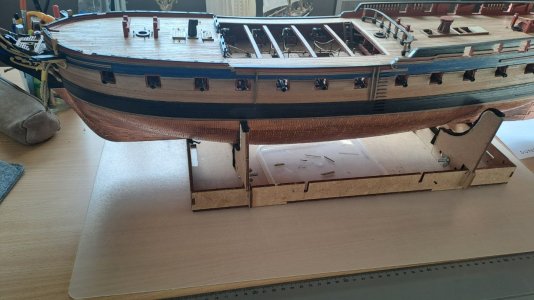
I started the kit in September, and I'm currently just about ready to start the first planking. I've also completed all of the cannons, carronades, and deck fittings. I have about 2 more years to go at my present rate of working on this kit 3 hours per day.
Thank you for your very useful (to me) build log. Your model is looking very nice. Can't wait to see it finished.
Sal
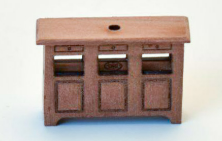
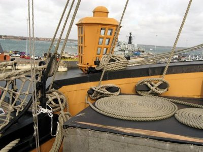
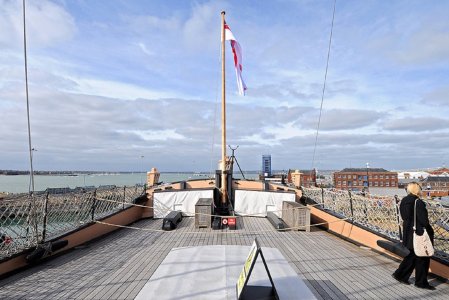
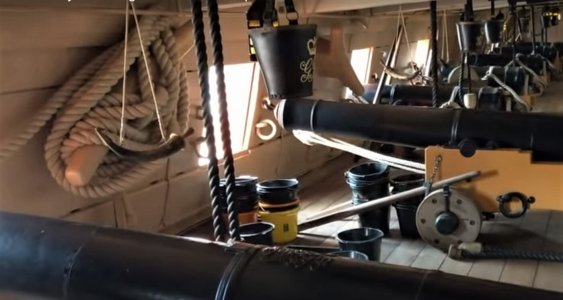
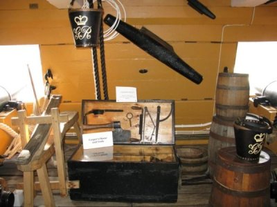
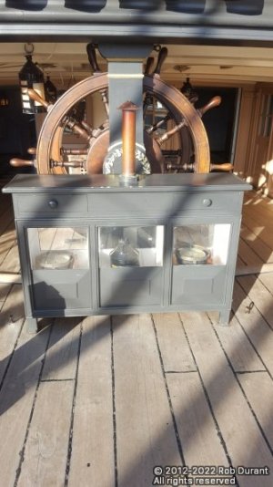
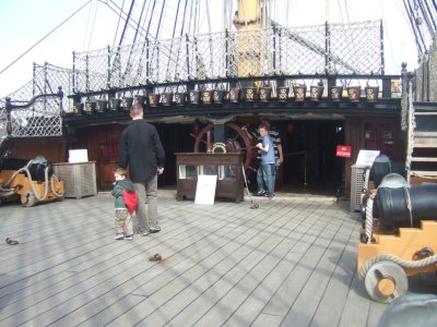
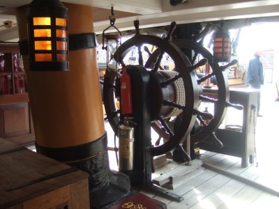
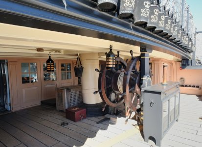
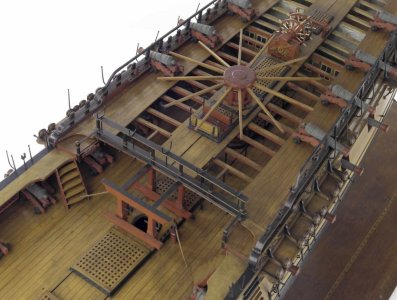
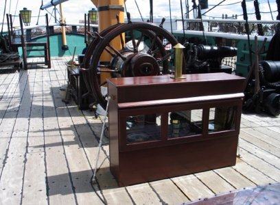
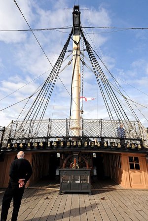
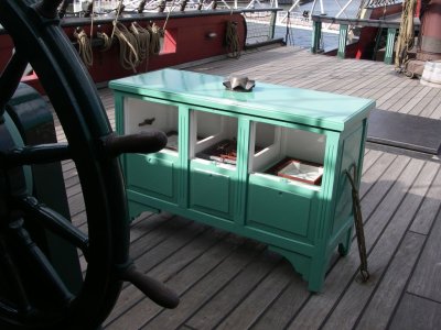
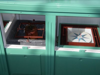
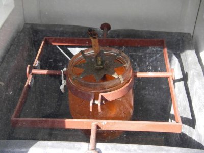
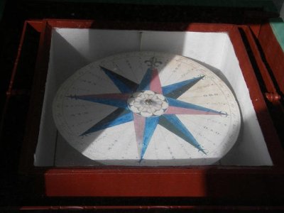
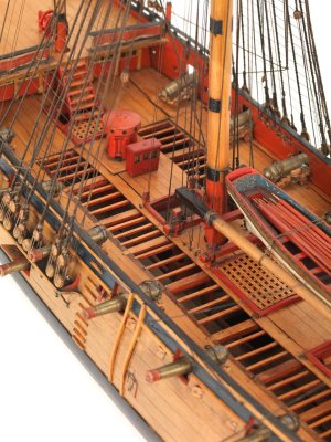
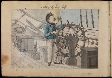
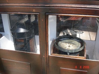
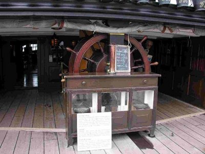
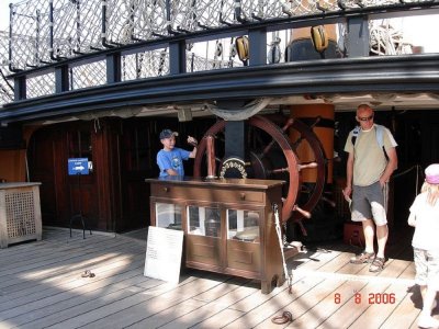
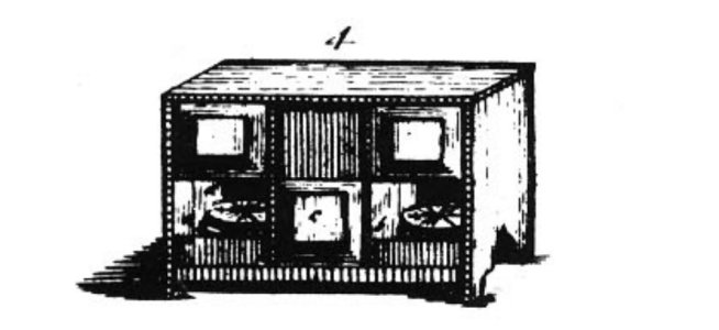
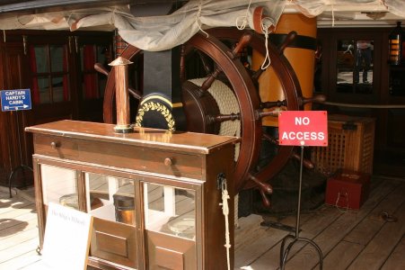
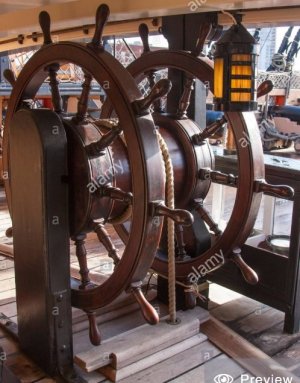
Hello Mark! English binnacles, despite the general design, differed slightly in size on different ships. The main thing is that the height of the binnacle should be such that its top cover can be used as a table for working with nautical charts and instruments. Approximate dimensions of the binnacle in 1/64 scale: height 16 mm (approximately one meter, including legs and table top, but without pipe), length 26 mm, width 8 mm. Windows 5x4 mm. Count the drawers and window covers from the photographs.


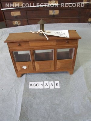
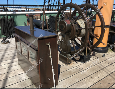
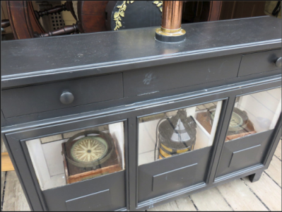
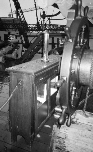


Hey Sal,Hi Marc,
I started the kit in September, and I'm currently just about ready to start the first planking. I've also completed all of the cannons, carronades, and deck fittings. I have about 2 more years to go at my present rate of working on this kit 3 hours per day.
Thank you for your very useful (to me) build log. Your model is looking very nice. Can't wait to see it finished.
Sal
Be welcome with any question!
Cheers
Marc
Dear Iutar,
I am indebted to you! Merci.
I will add a binnacle unit.
Cheers
Marc
I am indebted to you! Merci.
I will add a binnacle unit.
Cheers
Marc
Hello Mark! English binnacles, despite the general design, differed slightly in size on different ships. The main thing is that the height of the binnacle should be such that its top cover can be used as a table for working with nautical charts and instruments. Approximate dimensions of the binnacle in 1/64 scale: height 16 mm (approximately one meter, including legs and table top, but without pipe), length 26 mm, width 8 mm. Windows 5x4 mm. Count the drawers and window covers from the photographs.
View attachment 489676
View attachment 489673 View attachment 489674 View attachment 489675 View attachment 489677 View attachment 489678 View attachment 489679 View attachment 489680 View attachment 489681 View attachment 489682 View attachment 489683 View attachment 489684 View attachment 489685 View attachment 489686 View attachment 489687 View attachment 489688 View attachment 489689 View attachment 489690 View attachment 489691 View attachment 489692 View attachment 489693 View attachment 489694 View attachment 489698 View attachment 489696
Dear Iutar and or Allan,
I need my specialists again !!!!!!!!!!!!!!!!!!!!!!!!!!!!!!!!!!!!!!!!!!!!!!!!!!!
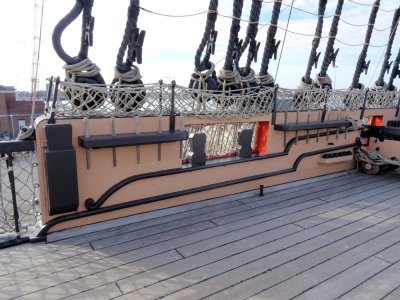
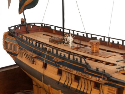
I have been working on the various cleats for the forecastle and quarterdeck.
The cleats at the stern are straightforward but I am confused as to how the other parts should look.
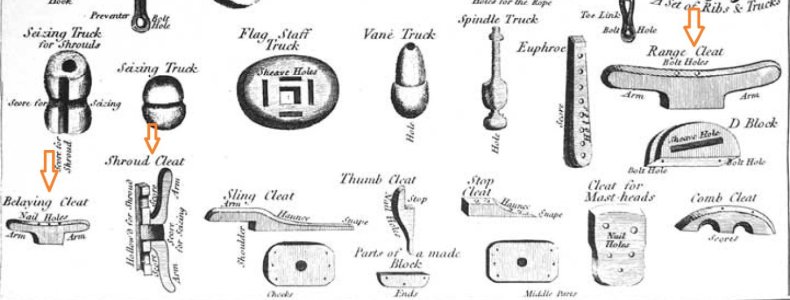
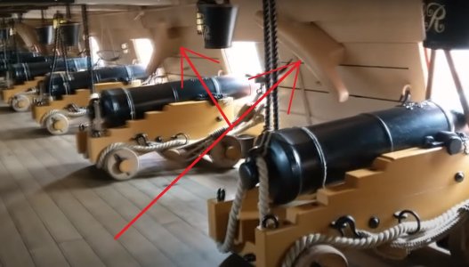
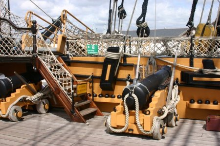
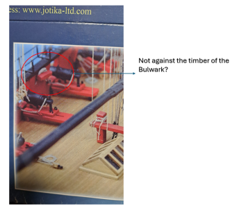
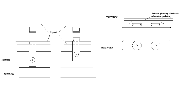
The kit includes Part 114 which is a cavel cleat and part 115 is another cavel block. Caldercraft gives no detailed indications of whether sheaves should be added but if the cavels are glued directly to the inner bulwarks: I don’t see how they could function.
Should the cavels be glued directly to the Bulwark timber?
Or, as in the picture of the Caldercraft kit-packaging, should there be a gap between the timber and the cavel?



Fly,
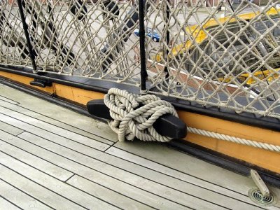
According Lees, cavel cleats have two sheaves and are bolted to the bulwarks in a horizontal position like the drawing on the right. Clavel blocks are vertical and look like the drawing on the left in your post. The drawings you posted definitely look correct. The sheaves are inside the cleats and blocks just like a common block and sized for the ropes (the sheave was 10% greater in width than the diameter of the rope) which typically include the various halyards, all of which are different sizes. I have no idea on the thickness of these cavels but I THINK it would be safe to assume the same proportions of block thickness would work for the thickness of the cavels and cleats. I looked in Steel (1794) (https://maritime.org/doc/steel/) as well and came up with nothing on cavels at all. Hopefully another member will have something more detailed for you.
Allan
Last edited:
Dear Iutar and dear Allan,
You are off course right...
Buth yes, facing again one of Caldercrafts mysteries: I found on the rigging drawings that the Cavel, altough not mentioned neither in the specs nor in the relevant drawing, should be mounted at +- mm from the "wall"...because this space is needed for rigging cords... So no other choise...
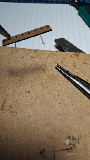
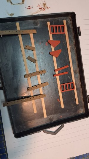
Meanwhile continuing with the preparation of the deck attributes...
PS
I recommend to insert pins (make a hole of mm because the Pin rail is only mm thick) because you will tighting during the rigging some cords...
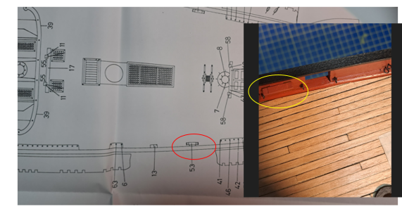


Fly, there is some misunderstanding here (probably only on my part.) Why would you want the cavels away from the bulwark? I may be wrong, but the below sketch is how I believe they would have to look to work. If anyone has more information that would be great. There are examples of the two layouts on the left on the contemporary model photos above. I think sometimes there were cleats next to the cavel blocks for belaying rather than a timber head type shape.should be mounted at +- mm from the "wall"...because this space is needed for rigging cords.
Allan
Last edited:
Dear Allan,
Your explanation is more than excellent and historically always correct... I am very grateful for your knowledge transfer And my research confirmed your information...
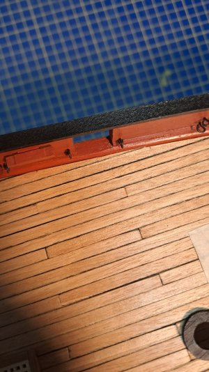
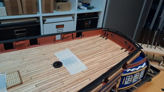
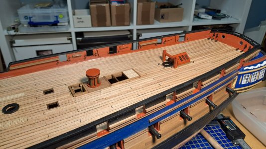
But for the Caldercraft rigging you need to glue the Cavels 1mm from the timber. Because you need to attach a cord around it...So I only kept them 1mm away...I know it is not historically correct, but I had a choice: this solution or problems with the rigging.
In the meantime I attached the Pin Rails. And this because everything is easily accessible, i.e. there are no things in the way.. (I had to drill holes every time to insert the pins).
Marc
Your explanation is more than excellent and historically always correct... I am very grateful for your knowledge transfer
But for the Caldercraft rigging you need to glue the Cavels 1mm from the timber. Because you need to attach a cord around it...So I only kept them 1mm away...I know it is not historically correct, but I had a choice: this solution or problems with the rigging.
In the meantime I attached the Pin Rails. And this because everything is easily accessible, i.e. there are no things in the way.. (I had to drill holes every time to insert the pins).
Marc

As discussed in the past, it always a good idea to check everything before trying to fix it in place. By adding the spacing you pretty much accomplished the same thing as remaking new ones or carving away some wood on the ones that they provided. Good for you to catch this and fix it before you went to belay theBut for the Caldercraft rigging you need to glue the Cavels 1mm from the timber.
first line.
Allan
Looking beautiful Marc.
You are building a worthy vessel.
You are building a worthy vessel.
Thank's for the very positive rating!Looking beautiful Marc.
You are building a worthy vessel.
Marc


