HMS Diana by Caldercraft

Dear Iutar,

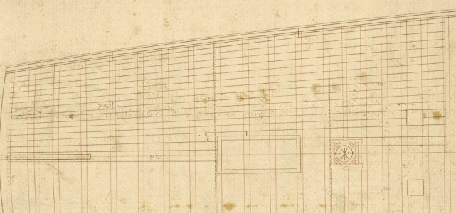
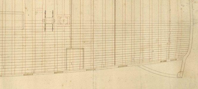
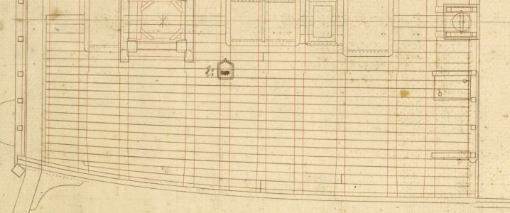
I took the necessary time to thoroughly study the old drawings.

I will definitely make the following changes:
1-No Short boards and wood chips
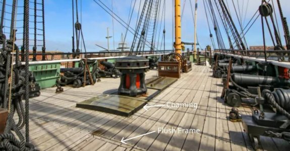
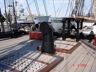
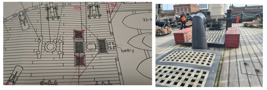
2 -Special hatches for rigging near the mast without coamings. The gratings installed flush with the deck
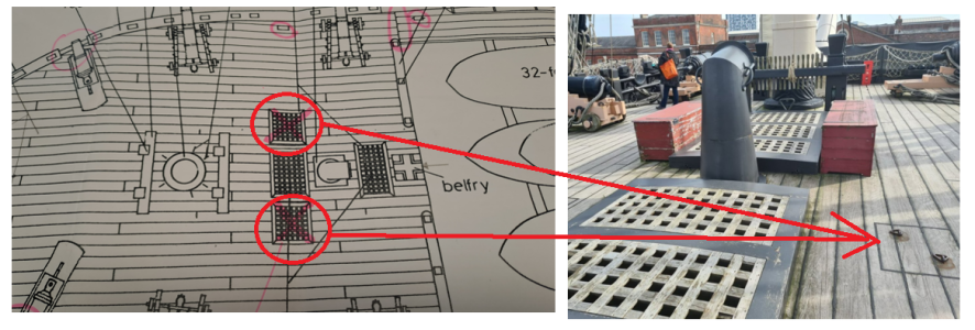
3-Two small hatches behind the mainmast are intended for wiring hoists without coamings, no grilles.

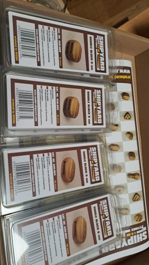
I received several hundreds of riggings blocks... very detailed and beautiful. Buth you have them to assemble yourself:
A lot of work but the result wil be fantastic.,, ;)
 
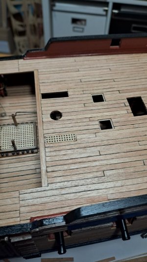
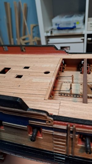
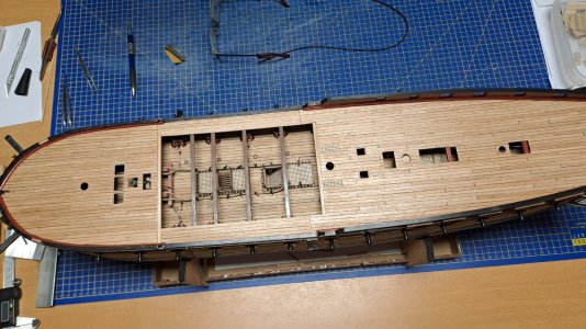
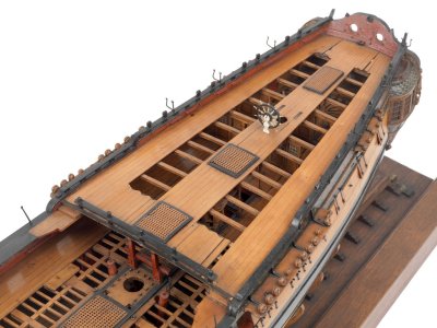
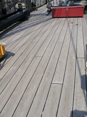
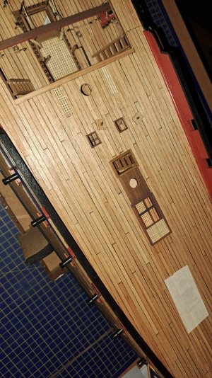
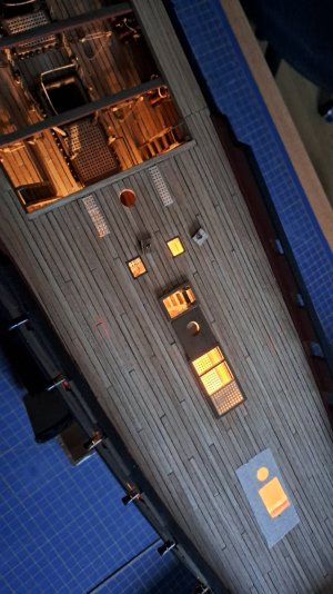
Voila, the Main Deck planking. A few things I would like to emphasize: as drawn on the original plans
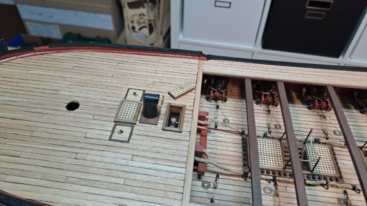
I avoided short boards and wood chips.
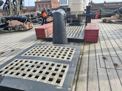
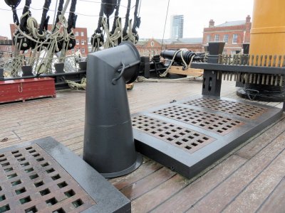
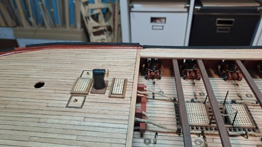
The hatches for rigging near the mast without coamings. The gratings are installed flush with the deck.

Next are the small hatches behind the mainmast (intended for wiring hoists, with the help of which the main topmast was raised and lowered).
No coamings, no grilles. The hatches will be closed with caps made to fit the deck flooring...

Iutar, I hope you are satisfied ? ;)

Cheers

Marc


1733757712792.png

Diana672.jpg

Diana674.jpg

Diana675.jpg
 
I avoided short boards and wood chips.
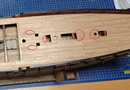
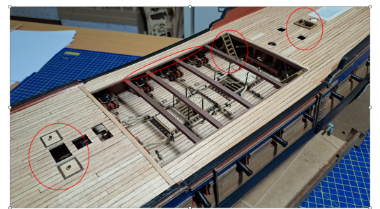
Dear Mark! Good afternoon! You say you got rid of the short boards and wood chips. But that's not true. :)
Answer this question: in real life, what would these details look like, and who would do such a thing? Would you make floors like this in your home? :)

Diana675.jpg


No carpenter would do that. Where circled in red, whole boards were placed without any problems.
It’s a pity that you didn’t show how the boards were inserted into the waterways belt. It would be beautiful.
 
how the boards were inserted into the waterways belt.
Hi Iutar
Do you have any drawings based on contemporary sources showing this that you can share? This may just be a matter of terminology, but I have not yet seen planking inserted into the waterways so this was new for me. I have seen drawings of the margin plank being cut to receive planking with snubbed ends as the ends should never come to a point. This was common practice in the 19th century. Prior to that joggling the planks was common.. This did not require nibbing into the margin plank. This was discussed in some detail along with drawings here at SoS in June. https://shipsofscale.com/sosforums/threads/deck-planking.14675/
Thanks iutar
Allan
 
Allan, good afternoon! Yes, I have an archived drawing of the deck flooring. But I think you will be interested in another drawing! As with the siding boards, this shows the minimal complications of the boards. It is interesting because the deck boards are made in such a way that they do not require insertion into the waterway at all. Each board is sharpened so that all boards fit into the required space. Only one "lost" belt shown!

палуба.jpg палуба 1.jpg алуба 2.jpg
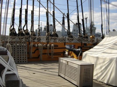
The same example is found on models from the Greenwich collection.
f8898_004.jpg


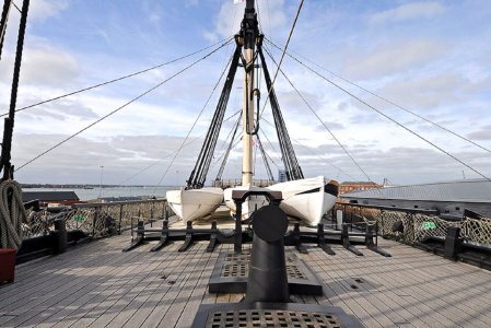
But the work of Brian Lavery, Jean Boudriot, Peter Goodwin (“The Construction and Equipment of the English Warship” by Peter Goodwin, mentioned in your link) and other authors is confirmed even by numerous living ships that I have visited.

*Sorry, "lost in translation". I didn't quite understand you correctly, Allan. Yes, I said that I regret that Mark didn't model the boards joining next to the waterway as shown on the previous page.
 
Last edited:
Thanks iutar. The drawings and model confirm the planking does not insert into the waterway. Sometimes they do insert into the margin plank as discussed before or are tapered in breadth as you show. What makes it even more interesting is when the outboard most strakes are hook and butt with oak, then elm or pine is used for straight strakes for the balance of the deck planks.
Allan
 
Dear Mark! Good afternoon! You say you got rid of the short boards and wood chips. But that's not true. :)
Answer this question: in real life, what would these details look like, and who would do such a thing? Would you make floors like this in your home? :)

View attachment 489191


No carpenter would do that. Where circled in red, whole boards were placed without any problems.
It’s a pity that you didn’t show how the boards were inserted into the waterways belt. It would be beautiful.

Hey Iutar, dear Allan,

I was expecting Iutar comment ROTF

Before gluing the strips I had drawn a detailed laying plan on paper (taking into account your recommendations not to place short pieces). But that resulted in an ugly deck plan. So I decided to emphasize the jump from one row of planks to the other which I find much nicer (the strips are 14 cm long and stagger every 3.5 cm).

On the other hand I didn't model the boards joining next to the waterway as shown on the model.
I tried but it was too difficult, I failed I couldn't bend the strips neatly to follow the Waterway.
The quality of the strips doesn't allow it either.
To achieve this I would have to use real planks instead of gluing strips to a plywood base... Something for my next model!

Cheers

Marc
 
The quality of the strips doesn't allow it either.
This is an all too common problem with planking materials from some manufacturers. Holly for light color wood, or for tan colors, Castello, or even basswood, is easier to work with in some cases. If you are narrowing the breadth of the planks as shown above, edge bending these pieces is not difficult as it is minimal. If stuck with poor quality wood you can try to thoroughly soak it and pin or clamp in place then hit it with a hot air gun or pre-form it using a jig as is done for hot edge bending hull planks.
Allan
 
Eh, Dear Mark! In fact, you could have made everything easier.
It would be better to use the traditional English version. It is both simpler and more reliable.

Forecastledeck0540.thumb.jpg.d1e5852ebee548e031bcf601ad70caef.jpg y_3e6cead8.jpg y_4ac50e99.jpg z_cf65e848.jpg
 
In fact, there is no need to adhere to the “joint through two/three/four boards” rule. This is stupidity and nonsense. This is not a law, not a rule, but only advice: “you need to make sure that there are as few joints as possible on one beam.” And use as many long boards as possible. Therefore, in principle there were very few joints, and the joints were unevenly located.

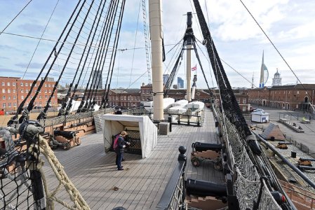
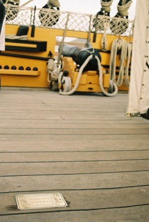
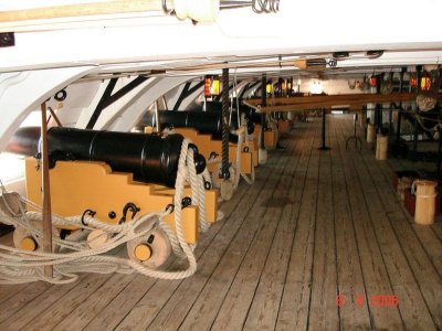
DSC_8882.jpg DSC_8890.jpg Here_Nelson_Fell_(216746145).jpg zOb-D5akA4E.jpg y_face9527.jpg 32411169647_35c38362aa_o.thumb.jpg.84e69711fea7047d78e5e5c62eac39db.jpg
 
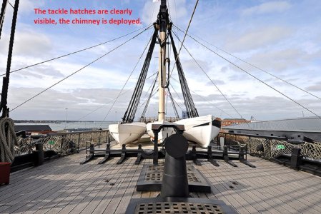
must it be oriented to the bow or as shown on the drawing to do inner side of the ship?
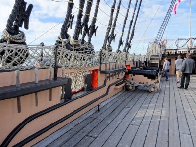
Dear Fly! The upper elbow of the chimney was removable and could be turned wherever you wanted. If you look closely, you can see handles on the Victory pipe for removing the upper bend of the chimney.

26345742805_dd422d3477_b.jpg
 
Do you like the removable gratings and hatches?
They look really good. Next time remember that the battens run fore and aft, not athwartships. It seems you have some of each. :)
Neatly done regardless, with very well done fitting.
Allan
 
Back
Top