-

Win a Free Custom Engraved Brass Coin!!!
As a way to introduce our brass coins to the community, we will raffle off a free coin during the month of August. Follow link ABOVE for instructions for entering.
-

PRE-ORDER SHIPS IN SCALE TODAY!
The beloved Ships in Scale Magazine is back and charting a new course for 2026!
Discover new skills, new techniques, and new inspirations in every issue.
NOTE THAT OUR FIRST ISSUE WILL BE JAN/FEB 2026
You are using an out of date browser. It may not display this or other websites correctly.
You should upgrade or use an alternative browser.
You should upgrade or use an alternative browser.
HMS Diana by Caldercraft
- Thread starter HMSFly
- Start date
- Watchers 37
-
- Tags
- caldercraft diana
No comment needed Marc!
How did you do the torn paper effect in your photo? I really like the look.
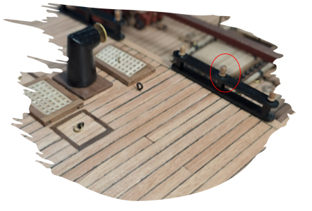
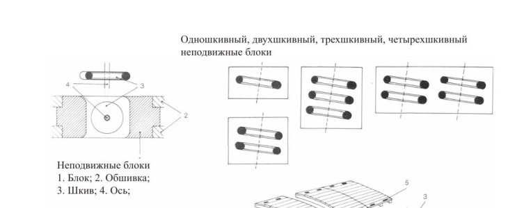
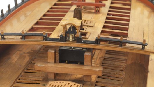
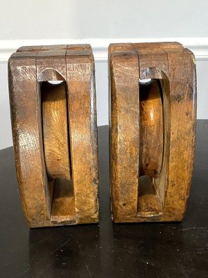
 Just as an FYI, from the The Elements and Practice of Naval Architecture the breast rail stantions on a 38 were 5" square not round and belaying pin handles were only about 2 inches in diameter so maybe not such a great match up to replace one with the other. Will you be adding the sheaves in the stantions as in the photo below? I think most folks are happy just drilling holes representing where the ropes will pass through the stantions, depending on the scale.
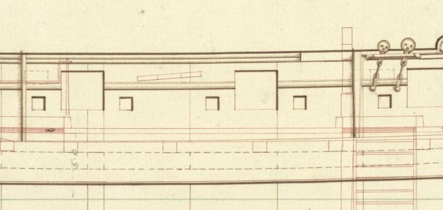
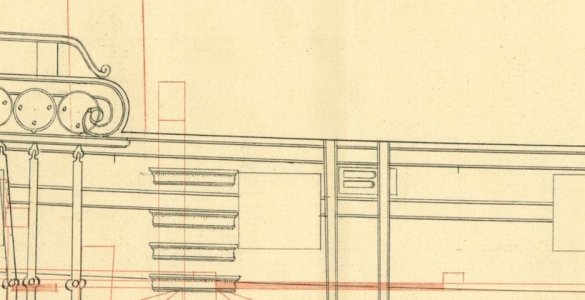
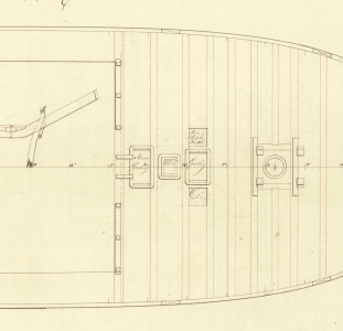
Diana/Artois class plan and contemporary model below from RMG Collections site may be helpful.
Your model, your choiceI sawed off the heads and look at the result: much nicer in my opinion.
Diana/Artois class plan and contemporary model below from RMG Collections site may be helpful.


Hello Allan,
You can almost read my mind: I have a question for you.
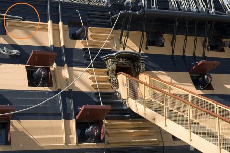
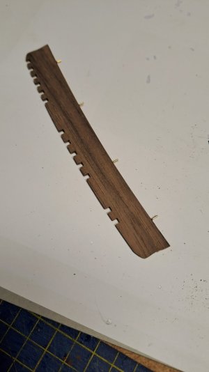
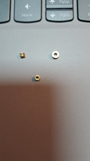
In the instruction Caldercraft is mentioning to drill holes in the Hull for below mentioned functions.
Were these in reality simply holes for the functions described on the plans? In my previous realization I provided sheaves instead of holes (rectangularity with pulleys).

PS1
I was (again) not aware that the breast rail stantions were 5" square not round.
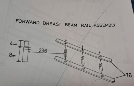
Below the instruction from Caldercraft : not square....
I saw a picture on the net of an old 18th century ship with the round ones...I will see if I can replace the round ones with squares...
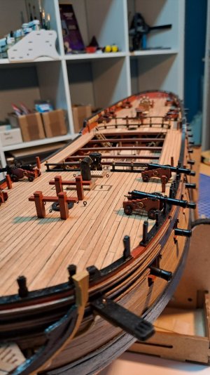
And below the progress...with the belfry etc...
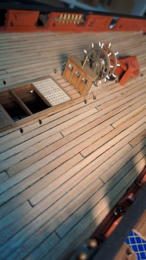
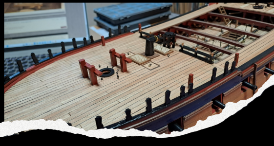
I'm going to place the attributes on the main deck first: next is the Wheel and the compass house...then the guns and then the rest...
PS
The paper effect is created in Microsoft PowerPoint with the designer option.
You can almost read my mind: I have a question for you.
In the instruction Caldercraft is mentioning to drill holes in the Hull for below mentioned functions.
Were these in reality simply holes for the functions described on the plans? In my previous realization I provided sheaves instead of holes (rectangularity with pulleys).

PS1
I was (again) not aware that the breast rail stantions were 5" square not round.
Below the instruction from Caldercraft : not square....
I saw a picture on the net of an old 18th century ship with the round ones...I will see if I can replace the round ones with squares...

And below the progress...with the belfry etc...
I'm going to place the attributes on the main deck first: next is the Wheel and the compass house...then the guns and then the rest...
PS
The paper effect is created in Microsoft PowerPoint with the designer option.


Iutar has answered and I am in total agreement. No line passed through a hole without a sheave that I can think of. BUT, like blocks, depending on the size and scale of a model, these are more often than not faked to just show you have two holes without the sheave. The sheaves were lignum vitae wood so if you just chisel out a little wood between the holes it will be very close in appearance to a sheave and once a line is passed through, barely noticeable. If you do add sheaves and use brass it would be best to blacken it rather than have a shiny metal sheave (unless you want to show off your detailingIn the instruction Caldercraft is mentioning to drill holes in the Hull for below mentioned functions
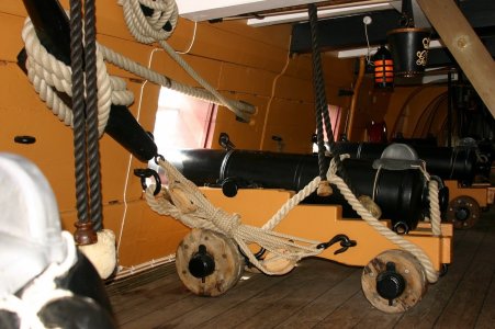
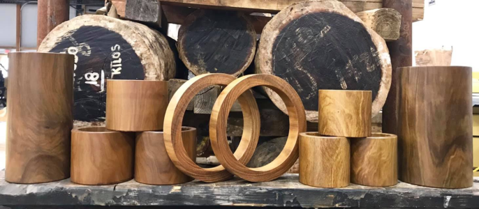
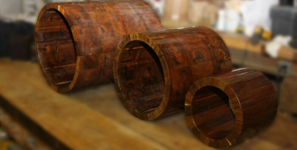
LV is a fantastic species of wood. Every ship I worked on had lignum vitae for propellor shaft bearings where it passed through the hull. I have no idea if they still use it, but it worked. (LV bearing rings in the photo below.)
Allan
Last edited:

Lignum vitae - Wikipedia
I will support Allan. LV was often used to make bearings and sheave inside blocks. Even today, LVs are used on submarines.
Again, thank you both so much...
I will add sheaves but would like to show the detail so probably I will leave the bras as it is...
Thank you so much!
Marc
I will add sheaves but would like to show the detail so probably I will leave the bras as it is...
Thank you so much!
Marc
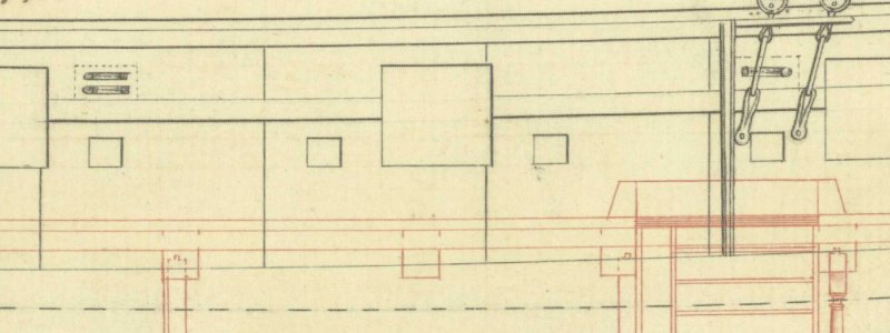
Dear Allan! I found this drawing, it might be interesting.I just checked a bunch of contemporary plans and I cannot find any that show the sheave in the hulls. I am sure I have seen them in the past on some contemporary plans but I am guessing the draftsmen assumed everyone knew they were there so there was no need to draw them.
Nice progress, Marc!
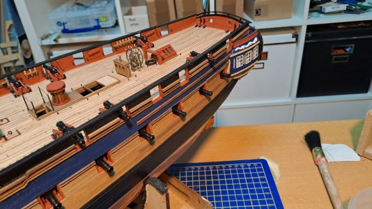
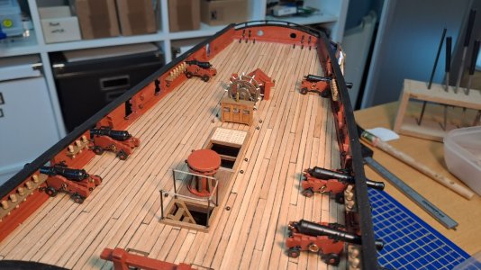
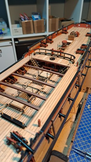
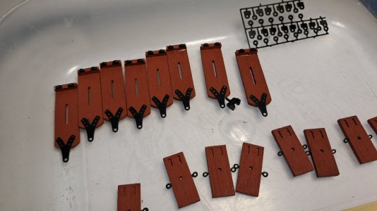
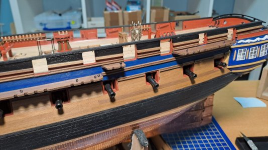
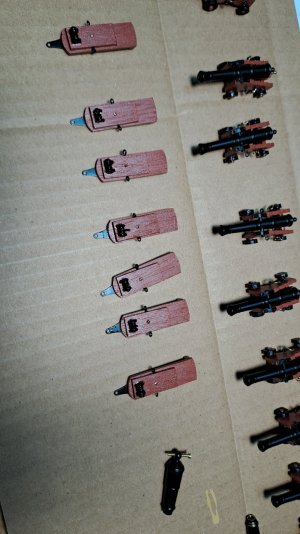
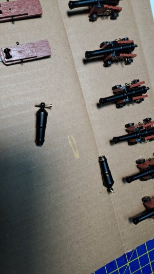
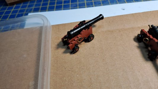
Good afternoon Marc. Wonderful attention to detail. Keep asking Allan and Iutar questions- their feedback is so valuable to noobies like myselfChristmas is of course a very busy period but still found time here and there to finish the 9 lb Guns and other details...
View attachment 492105
View attachment 492106
View attachment 492107
View attachment 492108
View attachment 492109
Hi Marc,details...


Happy Christmas to you.
The Diana is a beautiful ship, and in my shipyard next, and you are doing a wonderful job building this kit.
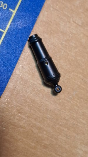
Can I ask if the carronades in the photo above are the ones supplied with the kit or aftermarket?
If aftermarket where did you buy them from? They look very nice.
Michael
Hello Michael,Hi Marc,
Happy Christmas to you.
The Diana is a beautiful ship, and in my shipyard next, and you are doing a wonderful job building this kit.
Can I ask if the carronades in the photo above are the ones supplied with the kit or aftermarket?
If aftermarket where did you buy them from? They look very nice.
Michael
The carronades shown are included in the kit: they are indeed the best and most beautiful I ever have seen...
