HMS Druid P.O.F. - Unicorn Models by Donnie [COMPLETED BUILD]

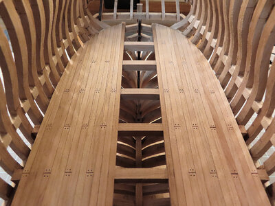
Donnie, another comment, now about that first deck. You mentioned that most of it will not be seen in the future. Like my Pegasus, that I left the upper deck without any planking so someone, with a flashlight can take a look inside. :)

Going to the point of your built.

Will that deck be seen through the frames, and partially from the main deck (as you mentioned) ?

If the side view, through frames, allows to see the deck, probably it will be nice to dress it with some "cargo type stuff, like barrels, boxes, whatever.

Just a thought!!

Cheers
Daniel
 
Donnie... sorry I am venting ideas. I see your last picture and I am imaging my future built.

If all that lower frame section will be without hull planking, I think it will be nice to add a few internal planks, below the deck you are showing us, and glue some small stone to show the ship ballasts. Just for decor and provide some unique features.

Now, you, or other experts, can tell me: Is that the place where the ballast was placed, at the bottom of the hull , bellow that deck ?

Cheers
Daniel
 
Daniel,

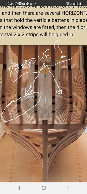
The purpose of the spacers (from what I understand) is so that when you are fairing the hull, it makes the hull nice and solid (feel) to it as the frames are rather delicate even though they are in a jig. I think I tried to sand some of the hull with only a partial amount of spacers and the frames do give 'back and forth' so that is not good.

Next, yes, there IS planking on the side of the hull. If you see the 'bottom' row of spacers, there will be three strips of planking and wales that extend lower than those spacers. Then the hull gets planked from that point all the way to the top of the hull.

I never did like the idea of the spacers and I think that personally, they are not needed. The only other reason why they might want to have the spacers is to make sure the frames are EVENLY spaced. But again, if I had to do this over, I would not add them. After the first and second DECK is done, most ALL of the spacers will be completely hidden and you will not be able to see them unless you had some type of swivel mirror or a dental mirror to look.

As far as the SUB Floor, yes, there is some type of STOVE that will go on that Subfloor, I just have not built the STOVE just yet. I think it has a PIPE that will extend out the upper decks. I have not studied that part much.

I have now gotten into the habit of reading and looking SEVERAL pages into the picture manual and for the most part I sort of disagree with the ORDER that they are taking to build this. For instance, they show laying each BEAM in place or Gluing each beam in place using the plans. NO - that does not work well as we all know that nothing is EXACT. This is the reason why I built my DECK support beam and carlings on the bench. Then all I have to do is LINE UP the first Beam (which coincidentally) lines right up on top of the FORE sub-floor. Then the whole Deck #2 Beam and carlings structure can be shifted fore and aft to get a good alignment.
I found that I was only off about 1mm or a little more. So basically I did not have any problems with the BEAMS falling into the correct place per plans.

I hope all this makes sense.

Oh, as a side note, DECK #2 will have DECK planking, but the CENTER part will NOT. It is interesting that they show the HULL planking done nearly BEFORE all of this. I DO NOT want the HULL planking in the way. t will block the view of a lot of things and then you have to work entirely from inside the ship.
I want to be able to see the entire frame as I am working on the decks. THEN, when I reach a certain point, then the planking of the hull will come next as the instructions call for cutting out the CANNON ports.

As a matter of fact, if it is possible, I am tempted to Plank DECK #2 and then install the whole assembly, BUT, there might be some obstacles that might keep that from happening. The reason is that some of the deck planking on DECK #2 that goes all the way to the STERN will have to be NOTCHED OUT to work its way AROUND the Frames. This is strange, but if you and others continue to follow, that step is coming up NEXT !!!
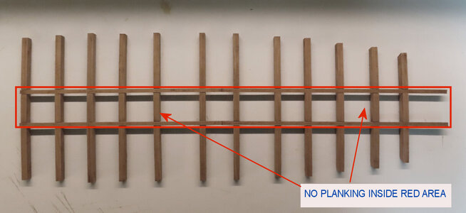
HKF-68-Planking.jpg
 
Last edited:
Thank you Donnie for the long and detailed answer.

Yes, of course I will continue to follow the built.

Cheers
Daniel
 
Hi Donnie

Reading again your answer to my comments. I am not sure if I understood it correctly.

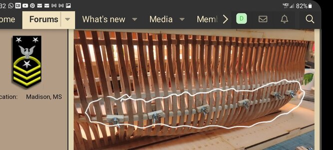
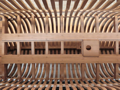
.....Next, yes, there IS planking on the side of the hull. If you see the 'bottom' row of spacers, there will be three strips of planking and wales that extend lower than those spacers...

You are referring to the middle row of spacers from the 3 rows you have in your pictures... correct ?

I went to see the finished model at ZHL Model and on their pictures the "bottom row" was removed.

Will you do the same and let on place the upper 2 rows ? Those looks like will be covered by the hull planks.

Screenshot_20210525-123005_Chrome.jpgScreenshot_20210525-121218_Chrome.jpg20210525_124056.jpg20210525_124154.jpg

Daniel
 
Thank you for pointing that out. I am aware of it. Well according to my measurements those spacers will stay. Unless I have really messed up somewhere along the way. I have taken measurements from the profile side view of ship plans. So I will see and investigate further when I get to that point.
 
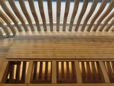
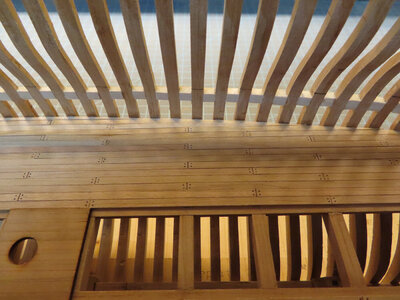
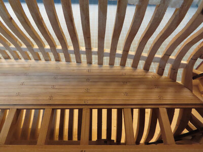
Continuation: Starting to plank the Deck. I am using this pattern (I am sure it has a name for it). They are staggered by three. I am not finished with tree nailing them. There will be MORE (single) ones in between the beams. It was easier to just cut each plank to the length I wanted and glue them it - very aggravating to try and glue in the entire length at once. Tried that and did not work. I even tried to do only half and that did not work well either. SO, I just decided to cut each one to length and it goes much faster and easier.

HKF-83.jpg
 
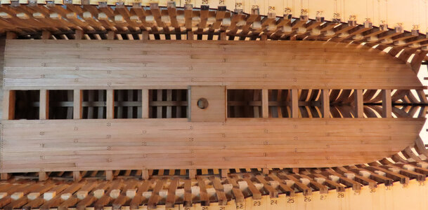
Thanks again for all the likes. It is greatly appreciated. Onward with almost closing in Deck #2. The central region will not have planks. I probably should not have spent so much time on the false treenailing as most of that will be covered up by Deck #1, but we will see how it all turns out. At least I know it is all there !!! :)

The first image is of the Stern view. As soon as this part is done, I must Plank the Hull next (and I am NOT looking forward to that at all). Thank goodness only a portion of the hull is planked.

HKF-85.jpgHKF-84.jpg
 
Donnie,
what's the length of the hull from stem to stern without the bowsprit fitted please ? Looking good.

Edit, just noticed its 65 cm according to the box on your first post.
 
Very good deck planking Donnie. I have no doubt that your skills in planking the hull will result in a very satisfactory outcome! Not to fret!
 
Hi Daniel!

View attachment 236786

View attachment 236784
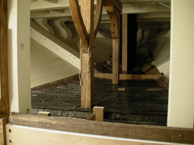
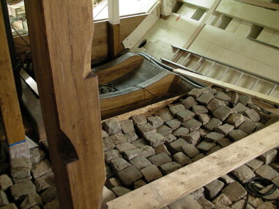
Ship's ballast of Hermione - old road paving from Rochefort at the deepest point in the ship above the keel. For Donnie's construction too late.

Thumbs-UpAs I see it, Donnie attaches great importance to the wooden structures and a very clean construction style. Thumbs-Up

Best regards
Thomas
Hallo Thomas,
the first photo is showing the iron ballast - I guess
Interesting to know, that on some harbor cities the road were paved with ballast stones from merchant vessels - so the other way around
Ballast-Stones-Savannah-Close-Up.jpg
here Savannah

 
Thank you all again for your likes. I was reviewing Wangs Druid and what a fantastic build he is doing. I do not think that I am going to go into that great of detail. However, I will be pleased to carry on with how my progress will be.

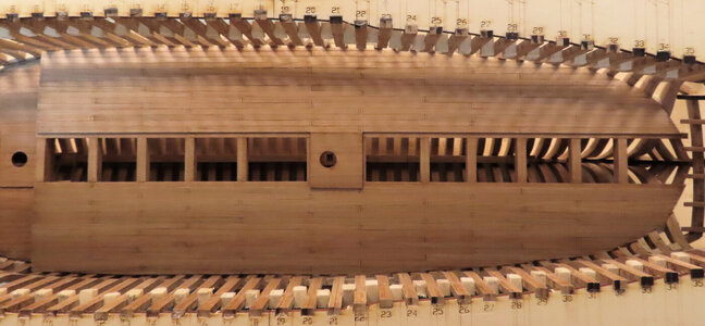
Therefore, I have completed Deck #2 Planking.

Onward to the Hull Planking - So, I have been studying this with images in the pictorial manual and some things I have seen online and also of course following the plans this is what I have come up with.

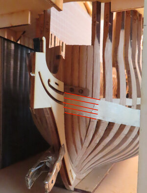
I marked off the area with Masking tape of where the WALES will be. The first layer of WALES uses Dark Walnut at 3 pieces 1.5 mm thick and 4 mm wide and ONE piece at 1.5 mm thick and 5 mm wide. THEN, this LAYER will be covered with another LAYER except this time again using Dark Walnut at only 1mm thick. The widths are the same.

Then according to the manual, there will be 1.5 mm thick and 4mm wide cherry that will go under these WALES and those planks will so happen COVER-UP the SPACERS.


FIRST THE COMPLETED DECK #2 (I AM ONLY SHOWING ONE SIDE)

HKF-87.jpgHKF-88.jpgHKF-89.jpgHKF-86.jpg


NOW THE LAYOUT OF THE WALES (USING MASKING TAPE).


hull-planking-01.jpg


THERE IS A (PLYWOOD) BOW TEMPLATE TO USE AS A GUIDE TO HELP LOCATE HAWSE HOLES WHICH IN TURN HELPS LOCATED THE FIRST WALES

hull-planking-02.jpg
 
Thank you all for the likes as usual.
Let me say that I am not in love with planking and for the strips to be only 500mm does not make it any better. The planking strips need to be at least 700mm - the reason is that you can make a much better Butt spacing like it is supposed to be. It is hard to get the number of Butt Joints like you want it when the strips are not long enough.
Pictures will be coming soon of the damages so far ;)
 
Donnie you have followed a very methodical approach with the planking. Just eyeing the wales as per your masking tape, indicates a very "easy on the eye line" - normally a good indication that they will be spot on. I have every faith in your ability - take your time and if it is one plank at a time - so be it.
 
Thank you all for the likes as usual.
Let me say that I am not in love with planking and for the strips to be only 500mm does not make it any better. The planking strips need to be at least 700mm - the reason is that you can make a much better Butt spacing like it is supposed to be. It is hard to get the number of Butt Joints like you want it when the strips are not long enough.
Pictures will be coming soon of the damages so far ;)
I'm puzzled here - 700mm plank length (~27")?! I believe this model is in 1:48 scale. That would make plank 108 ft long - not doable in real practice. Most likely I misunderstood something here. Nice work.
 
Back
Top