You are a fast builder - in some time you have overtaken me in building the gRanado
Very good progress
Very good progress
 |
As a way to introduce our brass coins to the community, we will raffle off a free coin during the month of August. Follow link ABOVE for instructions for entering. |
 |
 |
The beloved Ships in Scale Magazine is back and charting a new course for 2026! Discover new skills, new techniques, and new inspirations in every issue. NOTE THAT OUR FIRST ISSUE WILL BE JAN/FEB 2026 |
 |

Hi Uwe. Not overtaken, l've just done my build in different stages to yours as l am not making the hull in 2 sections. l have a long way to go until l get to your stage, which is near completion and also a long way to go to achieve your level of perfectionYou are a fast builder - in some time you have overtaken me in building the gRanado
Very good progress

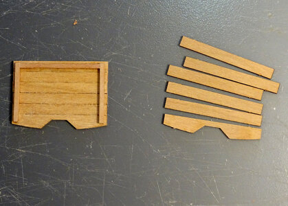
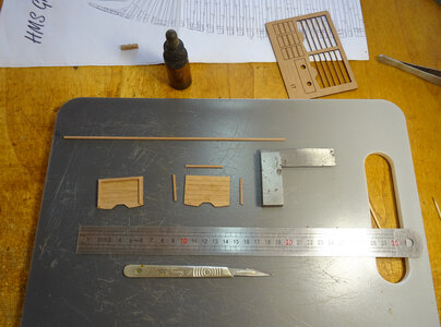
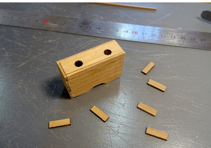
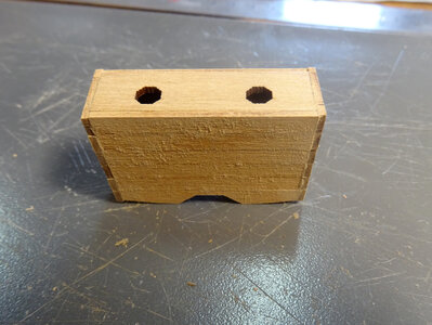
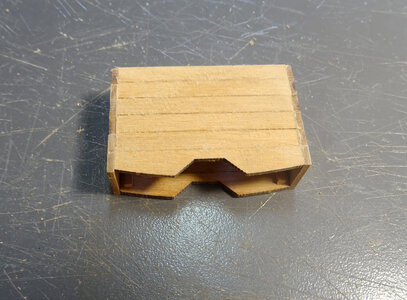
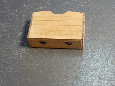
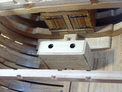
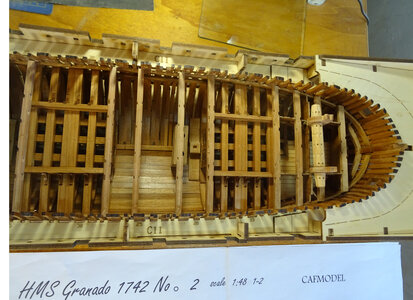

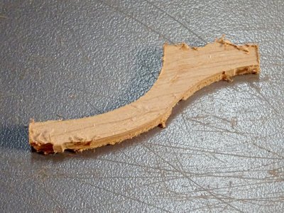
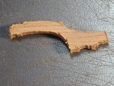
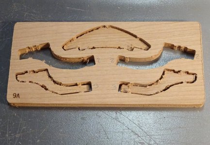
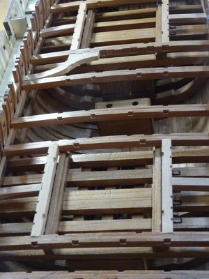
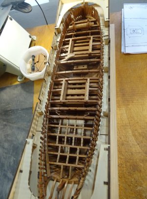


Thanks Paul, that´s exactly what l am planning on doing. Great minds think alike, eh!Hello Keef,
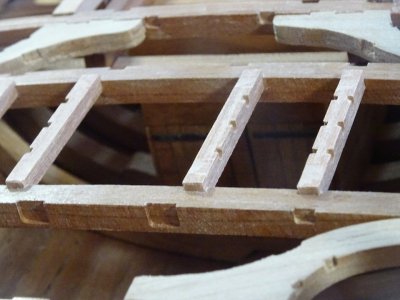
I think you will find it much easier to carefully notch the underside of the carling than to adjust the pocket in the beam. At least that was my experience...
Or…….”fools never differ “…..I couldn’t help myselfGreat minds think alike
 . Sorry Paul and Keith definitely not applicable to your modeling minds and skills, more so for myself and my riding buddies
 . Cheers Grant

Thanks Daniel. A very interesting comment, so just out of interest l looked it up. It appears it took a charge of 20 lbs of gunpowder to hurl a 13 inch shell that weighed 204 lbs plus a 7 lb explosive powder charge at an optimum angle of 41 degrees, a maximum distance of 2 1/4 miles. So yes that would have been one helluva kickBeautiful Keef, every time I look at your build, I try to imagine the thumping recoil wallop those mortar guns had.

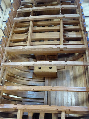
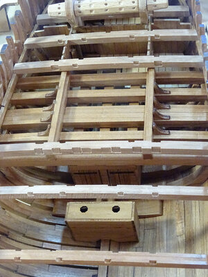
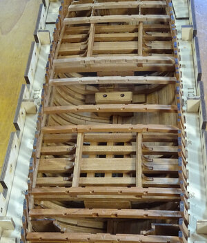
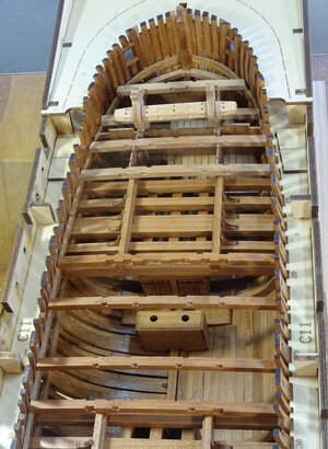
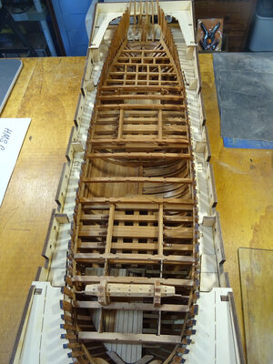
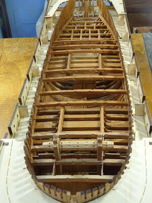
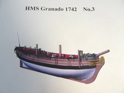
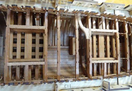
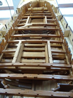
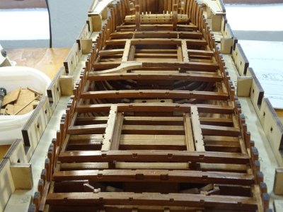
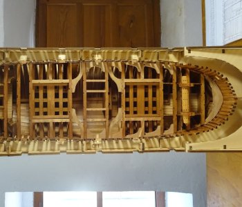
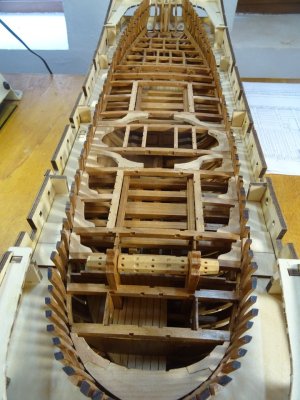
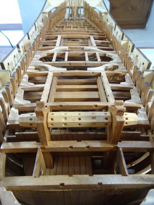
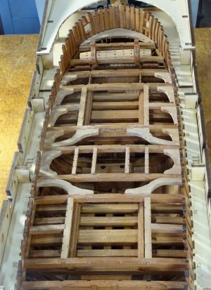
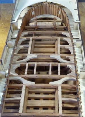
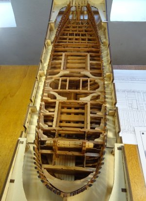
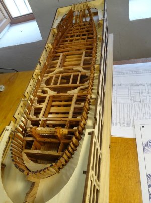
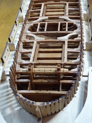
Great job, Keith. Love all the bracing in a ship like this. A lot of trees gave their lives for this one!The centre section over the hold is now complete with all the upper deck beams, including carlings, ledges, knees and main mast partners. l love to see it all coming together. This, as well as the construction of the ribs, is my favourite part of any POF build . . . Well l like it all really
View attachment 470084
View attachment 470085
View attachment 470086
View attachment 470087
View attachment 470088
View attachment 470089
View attachment 470090
View attachment 470091
View attachment 470092
View attachment 470093
View attachment 470094
View attachment 470095
View attachment 470096
View attachment 470097
View attachment 470098
View attachment 470099
View attachment 470100
View attachment 470101
View attachment 470102
View attachment 470103
View attachment 470104
View attachment 470105
View attachment 470106
View attachment 470107
View attachment 470108

Thank you Signet. Yes, you're right and this is a relatively small ship, although heavily braced. Imagine a huge, in comparison, ship like Victory or ConstitutionGreat job, Keith. Love all the bracing in a ship like this. A lot of trees gave their lives for this one!
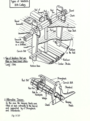

Hi Jimsky. Thank you very much for your interest in my build and your comments about the windlass. It is still very much WIP at the moment and the windlass, bitts and supporting beam are not fixed in position into the hull. It is removable so the 'ironwork' i.e. bands and endcaps can be fitted later. The pawl or ratchet device is fitted with the belfry when the forecastle timbers are prepared and placed. Hopefully everything should then fit nicely into placeI like your job and the model you are building. If you don't mind, I have a question about the windlass, unless it is still a work in progress (for windlass), the way it is presented now is missing some essential parts like pawl gear and the Pawl rings. I kind of guessing they will be added at a later time. Here is the image of a typical windlass for your reference in case you might need it.
View attachment 470136
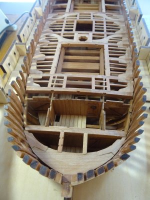
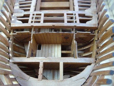
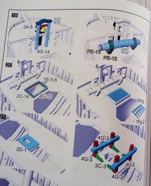
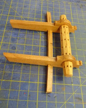

Thank you very much Uwe. There is a gap between every one of the lodging knees and hanging knees (l don´t know why this should be) but l have done exactly as you have suggested and filled them with sanding dust and glueVery good work on the lodging knees and the carlings - I remember well how much work it was
Maybe you try to fill the small gap between the main knees and the beam with some woodglue mixed with a lot of sanding dust .....
