-

Win a Free Custom Engraved Brass Coin!!!
As a way to introduce our brass coins to the community, we will raffle off a free coin during the month of August. Follow link ABOVE for instructions for entering.
-

PRE-ORDER SHIPS IN SCALE TODAY!
The beloved Ships in Scale Magazine is back and charting a new course for 2026!
Discover new skills, new techniques, and new inspirations in every issue.
NOTE THAT OUR FIRST ISSUE WILL BE JAN/FEB 2026
You are using an out of date browser. It may not display this or other websites correctly.
You should upgrade or use an alternative browser.
You should upgrade or use an alternative browser.
HMS GRANADO - full hull - POF kit by CAF in 1:48 - by Uwe
- Joined
- Apr 20, 2020
- Messages
- 6,257
- Points
- 738

my dear friend, excellent work, well doneIn the last post you realized maybe, that I have also installed the missing part of the deck structure close to the stern
and I also closed the gap with the missing carlings
View attachment 345774
One side will be planked, outside and also inside - on the other side the structure, also from the stern will be visible
View attachment 345780
View attachment 345775
View attachment 345776
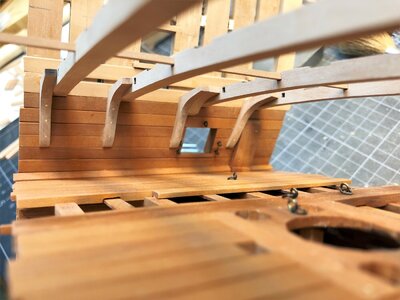
here you can see the hanging knees close to the stern - the upper part of the ship is laying here upside down
and now it is clear, why I was not able to install these knees before the big cut !
View attachment 345777
View attachment 345779
Many Thanks for your interest ..... to be continued ....

Oh my god, I missed the final cut, in my defence I didn't get a notification. I must say I am very impressed. Great work Uwe and I'm happy for you that everything worked out so well.
- Joined
- Oct 15, 2017
- Messages
- 1,191
- Points
- 443

Just catching up on your log Uwek. What wonderful results you've achieved! Great advertisement for those 2 little hand saws, although I think them being the the "right", steady hands had something to do with it. I'm still shaking my head in amazement at how you were able to achieve such a straight cut all along the hull. I'm sure you took your time.
On another note, I know I'm not quite 100% back yet as for a nano second, just a nano second, reading your post installing your handing knees, my mind thought, OMG he installed them upside down.
 But then I thought, it's UWEK, no way, so what am I seeing.....then realized you just had the entire deck upside down for illustration purposes.
Wonderful work!
On another note, I know I'm not quite 100% back yet as for a nano second, just a nano second, reading your post installing your handing knees, my mind thought, OMG he installed them upside down.
 But then I thought, it's UWEK, no way, so what am I seeing.....then realized you just had the entire deck upside down for illustration purposes.
Wonderful work!
Bonjour, Quel type de clou utilisez vous (diamètre, longueur) , et a quelle diamètre avez percé les avant trou ? merci d'avanceTo have a break during the partly boring pre-sanding, I decided to make also parallel the bolting of the frames.
I made the bolts in the for me usual method with copper nails - just thought about the new method introduced by Oliver, but I have not the patience in moment, so let us make the bolts "conventional" ..... with 50 nails per frame so in total also more than 2.000 "bolts"
View attachment 302678
also the single frames the chocks have to be fixed with bolts
View attachment 302679
Due to the fact, that I still do not know which parts I will plank on outside or inside, I decided to make the bolting of the frames everywhere
View attachment 302680
not really much is visible, but if you take a closer look - I know, that they are there - and we are building the models for ourself (and some interested modeling friends, like you all......
View attachment 302681
many Thanks for your interest .... to be continued .....
Hello, What type of nail do you use (diameter, length), and what diameter did you drill the pilot holes? thank you in advance
Many Thanks to @Mirek , @shota70 , @Tobias , @Hoss6262 and @Cathber for the kind comments and all others for the given likes / thumb upps
usually the small copper nails have 0,6 or sometimes 0,7mm diameter - predrilling of pilotholes is a must, although the timber of this kit are very good and splintering is extremely unlikely. I pre-drill with 0,5mm, so that the nail is slightly pressed into the wood, therefore no glue necessary.What type of nail do you use (diameter, length), and what diameter did you drill the pilot holes?
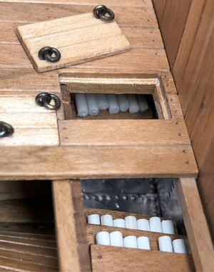
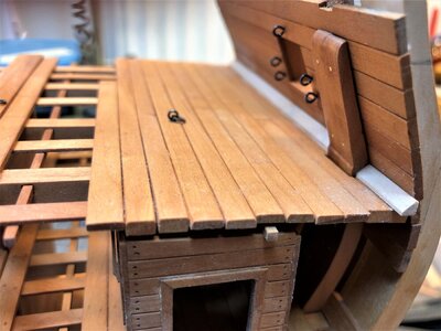
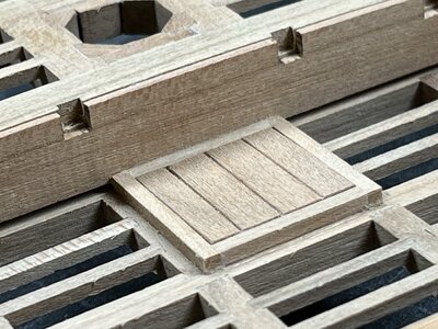
After finishing of the deck structure the next were the two smaller hatches and companion ways in the after cabin deck
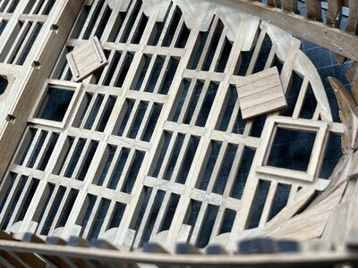
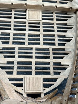
Under this a ladder will be installed, so therefore I am not sure if the cover will stay, but defintely the two ringbolts have to be installed
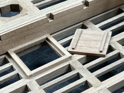
the same cover open and the bottom side visible
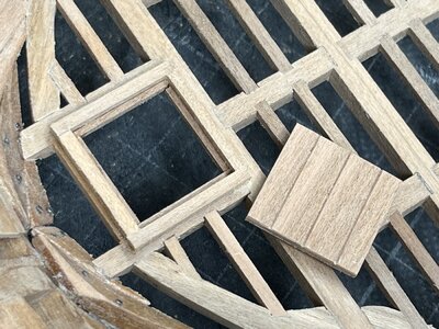
The small hatch down to the breadroom - also here the eyelets will come later
Many Thanks for the interest in my building log - to be continued


Under this a ladder will be installed, so therefore I am not sure if the cover will stay, but defintely the two ringbolts have to be installed

the same cover open and the bottom side visible

The small hatch down to the breadroom - also here the eyelets will come later

Many Thanks for the interest in my building log - to be continued
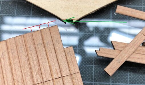
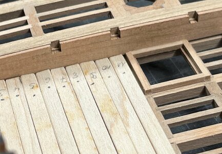
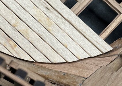
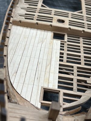
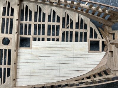
started also the deck-planking of the after cabin
This deck is inside, so no caulking necessary, but chamfered the edges to pronounce slightly the single boards.
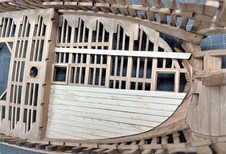
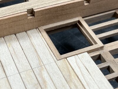
also on the other side I have to install some boards, so that the future cabin walls inside will have a base
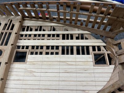
Many Thanks for your interest
This deck is inside, so no caulking necessary, but chamfered the edges to pronounce slightly the single boards.


also on the other side I have to install some boards, so that the future cabin walls inside will have a base

Many Thanks for your interest
That slight chamfering of the deck boards has me thinking...
It does create a very interesting visual effect. I guess I have not seen that done elsewhere though surely it has been used. Thanks for sharing.
It does create a very interesting visual effect. I guess I have not seen that done elsewhere though surely it has been used. Thanks for sharing.
I have caught up with your build log again.
Truly magnificent.
Chapeau.
Truly magnificent.
Chapeau.
Many Thanks @Herman and Paul alias @dockattner for your kind comments
I made this slight chamfering already some times on lower decks and also walls -> the small shadow produces more the impression of single boards. Especialy when there is no caulking. The upper Main deck will be "caulked" and a chamfering would be too much, especialy using paint to simulate caulking would get a big mess
The planking shown in my yesterdays post is fixed to the beams
a decision, if I will nail or treenail this planking is still open, maybe only immitated nails with only small dotts made by a scriber - but this decision can be done also in some days or maybe weeks
positiv with such a big cut: you can work on the deck or down in the hold - so a lot of work places
When something is getting boring, or decisions are not made -> no problem -> I will do something else
When you have these possibilities to work here and there, it's really nice. Great idea with the bevelled boards.
I am a big fan of chambering planks, like Paul mentioned, it is a great representation of individual planks. I know Uwe is a big fan too, he uses this method on past models as well.
BTW, your work is very accurate and looks very good!
BTW, your work is very accurate and looks very good!
After the yesterdays excurs about chamfering the boards, coming back to the progress on the Granado
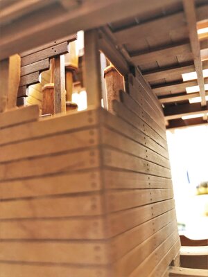
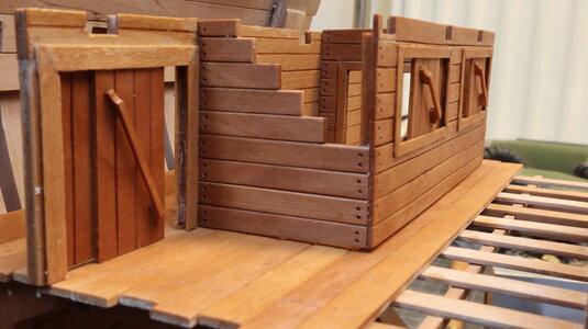
I started to make the interior walls of the after cabins
Here the plan excerpt from the Anatomy book
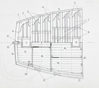
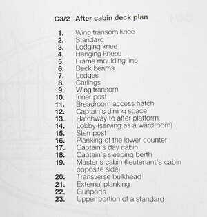
and the interpretation prepared by CAF
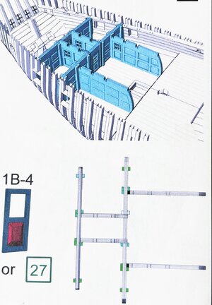
In the Anatomy book there are also some smaller sketches shoing these walls as casette walls - unfortunately I forgot to make a photos to show this "look", but I will catch up and post it on the next days
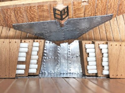
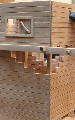
Now only for the beginning the clever way CAF is representing these kind of walls. Made out of three sandwhich elements, on which the outer parts are chamfered to get the look
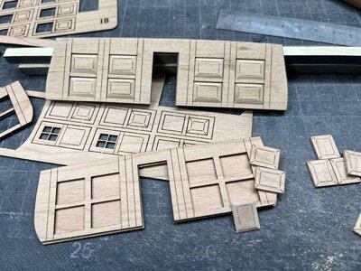
One of these main bulkhead wall contents all together 19 parts, with 8 casettes on each side
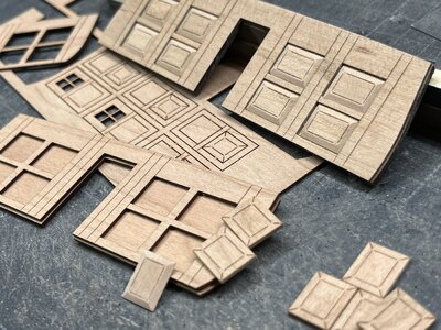
a first impression how these walls are looking like
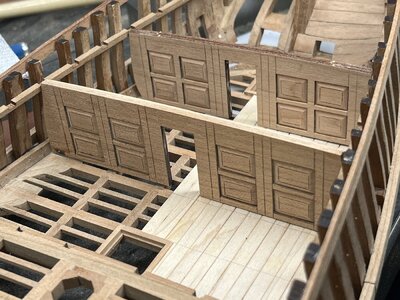
A lot of sanding - and I made them by hand with a sanding block
- YES YES - this could be done also with a mill, but I was too lazy - and I had to pay for this decision
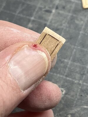
at the end I was "clever" enough to sand down my finger also in the same angle
-> In all of my models is minimum one drop of my blood and sometimes more
Many Thanks for your interest ..... to be continued
I started to make the interior walls of the after cabins
Here the plan excerpt from the Anatomy book


and the interpretation prepared by CAF

In the Anatomy book there are also some smaller sketches shoing these walls as casette walls - unfortunately I forgot to make a photos to show this "look", but I will catch up and post it on the next days
Now only for the beginning the clever way CAF is representing these kind of walls. Made out of three sandwhich elements, on which the outer parts are chamfered to get the look

One of these main bulkhead wall contents all together 19 parts, with 8 casettes on each side

a first impression how these walls are looking like

A lot of sanding - and I made them by hand with a sanding block
- YES YES - this could be done also with a mill, but I was too lazy - and I had to pay for this decision

at the end I was "clever" enough to sand down my finger also in the same angle
-> In all of my models is minimum one drop of my blood and sometimes more
Many Thanks for your interest ..... to be continued
The inner walls look really good, which can't be said of your thumb, sorry Uwe. I think we've all suffered such injuries.
....art requires sacrifice, but I love how the walls look. It is a very simple and quite effective solution to make walls look 'fancy' without involving a milling machine.
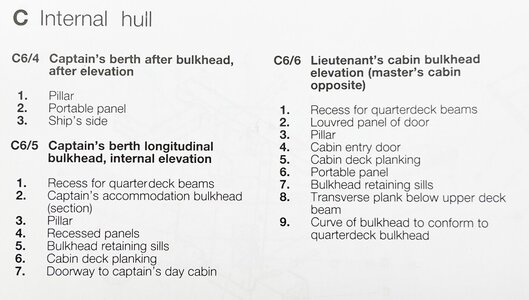
As mentioned yesterday here the look of the walls shown by Goodwin in his Anatomy bookIn the Anatomy book there are also some smaller sketches shoing these walls as casette walls - unfortunately I forgot to make a photos to show this "look", but I will catch up and post it on the next days
The cassetes are named here - "Recessed Panels"
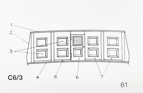
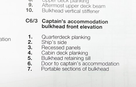
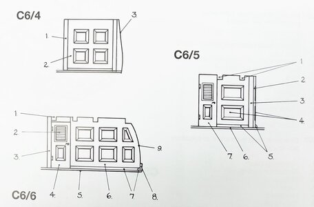
to everybody celebrating Christmas Eve -> MERRY CHRISTMAS
Stay Healthy and enjoy the time with your familys and friends
- Joined
- Jan 21, 2022
- Messages
- 891
- Points
- 403

Ouch.That must have hurt.
That elements on wall look very good and in my opinion you took the harder way, but it's good to show that machines aren't always necessary. I would definitely make it by milling(but I'm lazy


