HMS GRANADO - full hull - POF kit by CAF in 1:48 - by Uwe

After the yesterdays excurs about chamfering the boards, coming back to the progress on the Granado

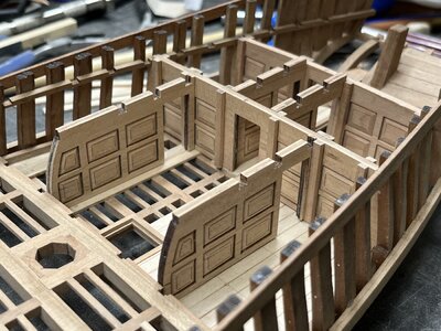
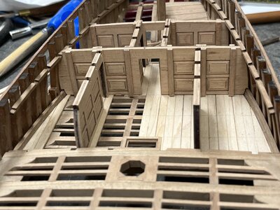
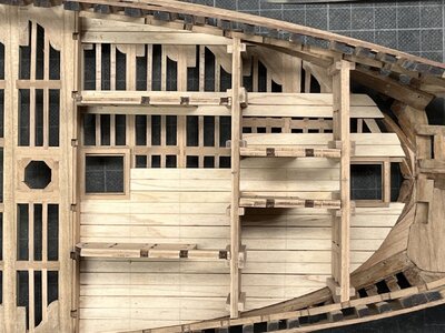
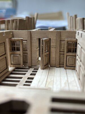
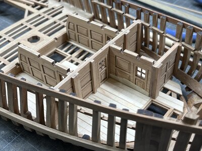
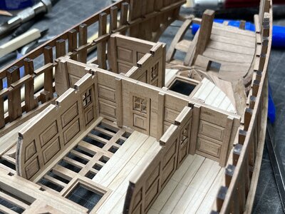
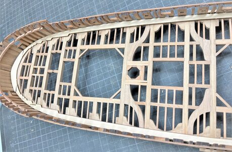
I started to make the interior walls of the after cabins

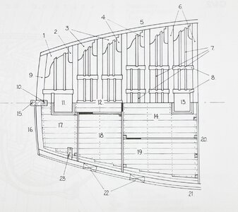
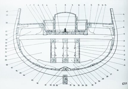
Here the plan excerpt from the Anatomy book
View attachment 346999

View attachment 347000

and the interpretation prepared by CAF
View attachment 346998

In the Anatomy book there are also some smaller sketches shoing these walls as casette walls - unfortunately I forgot to make a photos to show this "look", but I will catch up and post it on the next days

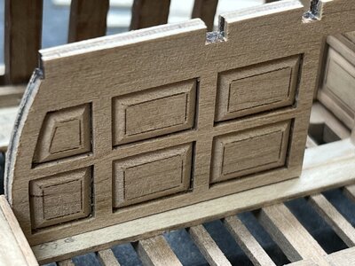
Now only for the beginning the clever way CAF is representing these kind of walls. Made out of three sandwhich elements, on which the outer parts are chamfered to get the look

View attachment 347010

One of these main bulkhead wall contents all together 19 parts, with 8 casettes on each side

View attachment 346995

a first impression how these walls are looking like

View attachment 346996

A lot of sanding - and I made them by hand with a sanding block
- YES YES - this could be done also with a mill, but I was too lazy - and I had to pay for this decision

View attachment 346997

at the end I was "clever" enough to sand down my finger also in the same angle
-> In all of my models is minimum one drop of my blood and sometimes more

Many Thanks for your interest ..... to be continued
It really looks a great kit and you are doing a fantastic job with it Uwek. l am seriously considering attempting this kit in the future (after my Blandford of course)
 
Hello.I have such a question for you.you have collected many sets of mine.which one of them would you recommend to me after my construction of the hayling POF?
 
It really looks a great kit and you are doing a fantastic job with it Uwek. l am seriously considering attempting this kit in the future (after my Blandford of course)
Hello.I have such a question for you.you have collected many sets of mine.which one of them would you recommend to me after my construction of the hayling POF?
Sorry for the late reply .... I had during my holidays very limited time to be online - my family and the animals had for the last two week priority.
But I had the chance to work a little bit more on my Granado.

But back to your questions:
@Keef :
I can fully recommend this kit, very good quality of material, highly interesting construction and I think with the cut also it will be a very interesting model at the end.
@NOVICHOK :
I do not know the alternatives in your collection, so I am not able to recommend this or that kit.
Until now I made in POF the Salamandre (hull), the Bonhomme Riochard section, the Granado section, the Le Coureur and now the Granado - every kit has some special and individual challenges - so I think it is always the best to decide for a kit which you like most - working several hundreds of hours on one project- it si necessary that you minimum like the model

and to everybody else following my building log

Happy New Year - keep care and safe, stay healthy and enjoy the modeling
 
Hello Uwe also to you a happy new year and I hope you enjoyed the time with the family. I'm sure you enjoyed it. I had to look at your final cut again and again before the holidays and had so a few strange thoughts whether I should also try. Really great work, I was already so excited about Martin's cut.
 
Many Thanks for the kind comments [ @Kurt Konrath , @Tobias and @Nomad ) and all the likes received
Much appreciated

I assume the notches on top are for fit of the next deck support timbers.
Correct - and they fit very good with the heights of the clamps - I made already the tests
 
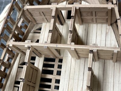
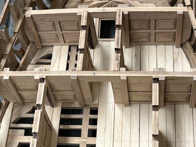
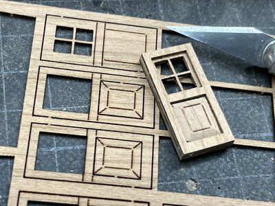
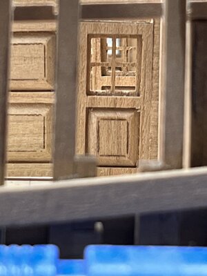
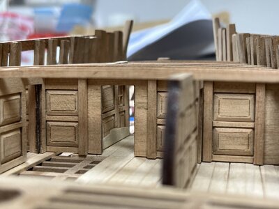
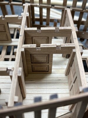
one of the next working steps were the small doors which are also developed by CAF on sandwich basis, similar to the walls

IMG_1693.jpg

only glued together but definitely not finished (final sanding and hinches etc.) - but enough to get an impression og how they will look like

IMG_1692.jpg

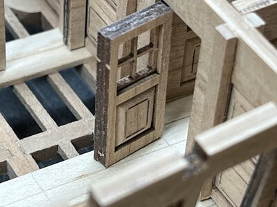
depending how finally I will install them (closed or open) I have to think definitely about reducing their thickness - especially, when they will stay open

IMG_1694.jpg

IMG_1697.jpg

IMG_1696.jpg
 
I completely agree with you, mon ami, the doors appear (at least from the photo view) a bit too thick. It is noticeable when you visually compare the thicknesses of the beams or just the walls. Even when the door is in the 'close' position you can observe the thickness thru the door windows. If you didn't glue them all yet, sanding the inner sides of the sandwich should do the trick before gluing. I am sure you already have the plan. :cool:
 
I am sure you already have the plan. :cool:
Unfortunately not - I have to admit, that I was to fast with going on with the build and did not think enough about this detail. doors are glued already.
So in moment I think, that I will leave them like they are and probably closed. Or maybe only one of the doors on the sides open, where directly a beam is located - the beam would cover the complete door when you take a view inside from the top.
I will not make a complete deck planking, so there will be some possibilities to look inside, but I can limit the perspectives........ I will see

Are you going to make working or at least fake looking hinges for all the doors?
The hinges will be fake and not working - I made working hinges on my section model, but at the end it is work for nothing - at the end the model will be covered by plexiglas. also, when it is free my fingers would be not slim and long enough to move a door. Too much beams and planks will hinder the access .......

and all others -> many many thanks for the likes received - much appreciated
 
Back to the interior walls and bulkheads

I made a further change and adjustment from the kit, which I want to explain in the following more in detail

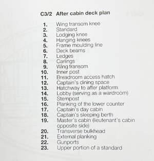
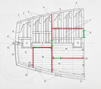
This is the sketch in Goodwins anatomy book showing the walls and defining the room arrangements
IMG_1706.jpg

The rooms are defined with
#12 - captains dining space
#17 - captains day cabin
#18 - captains sleeping berth
and
#14 - Lobby
#19 - Masters cabin - with the additional important information "lieutenants cabin on oposite site", which is not visible in the sketch, because there is no planking but the structure of beams etc is visible

Only this are the rooms

IMG_1707.jpg

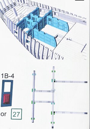
when we compare now with the walls prepared in the kit we can see this - there are more walls visible

IMG_1703.jpg

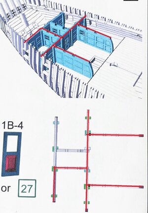
but when I (my personal) interpretation of Goodwins information - I would need only these walls, which are marked with red lines

IMG_1703a.jpg

To highlight them also in Goodwins drawing - the walls in red with the location of necessary doors in green

IMG_1706a.jpg

based on this I took my saw (in the meantime I like it very much to cut LOL)

IMG_1700.jpg

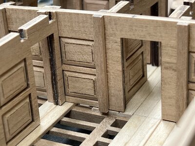
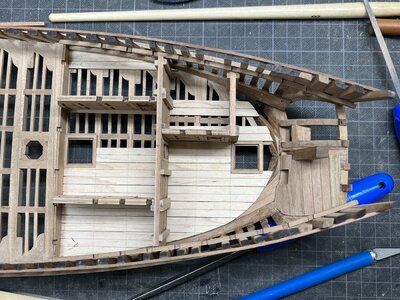
Now the captain has realy a much bigger room and the access of the rooms is making sense

IMG_1701.jpg

IMG_1702.jpg

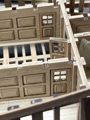
BTW: here we can see the doors closed - not looking sooooo bad, or?

Many Thanks for the interest in my work on this highly interesting model ....
 
Last edited:
@Jimsky and @Steef66
many thanks for the diplomatic comment - so I feel better now :cool:

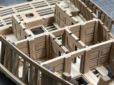
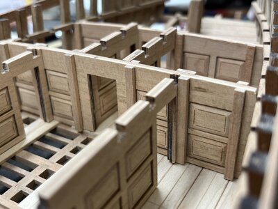
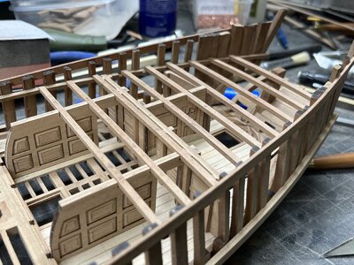
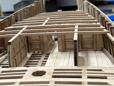
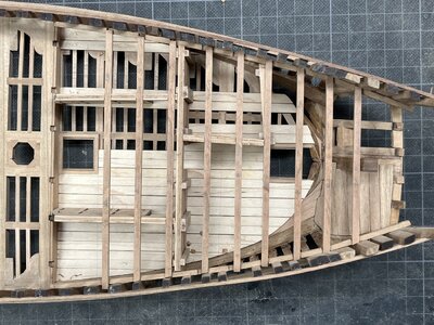
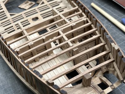
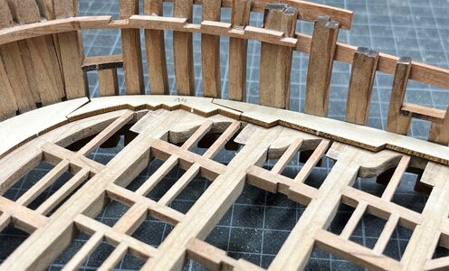
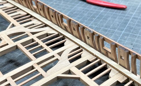
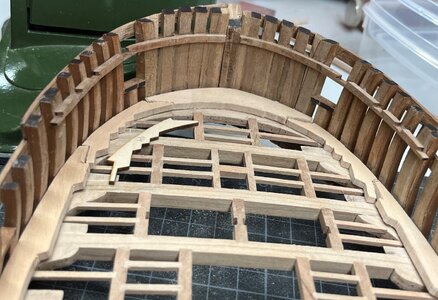
Here you can see this area of the after cabin with the walls and also the deck beams dry fitted

IMG_1708.jpg

IMG_1709.jpg


IMG_1711.jpg

the walls are not 100% correct aligned in moment

IMG_1712.jpg

but you can get a good impression of how good the notches in the walls and the small beams are fitting together - > I like this kit very much

IMG_1713.jpg

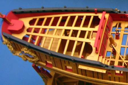
at the end with the deck beams over the cabin it will somehow look like the NMM model built by Robert Lightley

Screenshot 2022-12-01 164037.png

BTW: here we can also hardly recognize the interior walls in his interpretation which is close to my interpretation - only room #18 captains sleeping berth is missing
I did not find any better photos of this model to see the interior of the cabin

 
Before I can finalize the walls and deck of the after cabin I have to make the inner planking
and before I can make the inner planking I have to finalize the waterway(s) on which the planking / spirketing is laying ..... so

one of the next working steps will be the waterway(s)

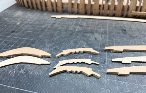
The kit offers the waterway segments on the sheet with the laser cut planking boards

Using these parts from the kit with the first fitting test

IMG_1533.jpg

The form fitts well (curvatur and also the joints

IMG_1534.jpg

IMG_1535.jpg

But ......

the waterway elements of the kit have off course the smae thickness like the deck planking (coming from the same sheet)

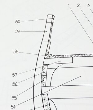
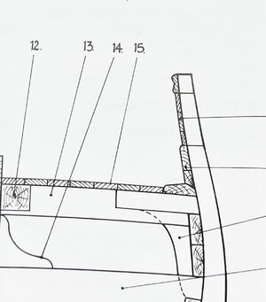
In the Goodwin book we know this cross section through the mortar
IMG-8025a.jpg

On the left side we can see the cross section of the waterway (edge to the planking in the same height) - slightly different on the right side where the edge is higher than the planking

IMG_1893.jpg IMG_1892.jpg

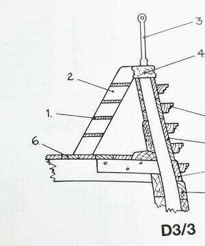
another cross section showing a waterway similar to the right on above

IMG_1891.jpg

But definitely (as usual) the waterway is made from an appr. double height wooden board than the normal planking

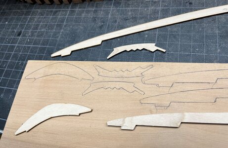
Therefore I decided to make my waterways in scratch using some thicker pear wood - also to produce some color difference compared to the planking

Using the kit parts as templates

IMG_1715.jpg

after some minutes with the scroll saw

IMG_1716.jpg

The first working step is done

IMG_1717.jpg

Now the inclinations have to be sanded, the outer form adjusted and the treenails to be made ..... step by step

Many Thanks for your interest .... to be continued ....
 
Back
Top