Very nice! I noticed in Historic Ship Models, waterways were not even with the deck but instead many are 'sculpted' to help channel water to scuppers. Nice job!Before I can finalize the walls and deck of the after cabin I have to make the inner planking
and before I can make the inner planking I have to finalize the waterway(s) on which the planking / spirketing is laying ..... so
one of the next working steps will be the waterway(s)
The kit offers the waterway segments on the sheet with the laser cut planking boards
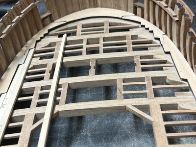
Using these parts from the kit with the first fitting test
View attachment 350944
The form fitts well (curvatur and also the joints
View attachment 350945
View attachment 350946
But ......
the waterway elements of the kit have off course the smae thickness like the deck planking (coming from the same sheet)
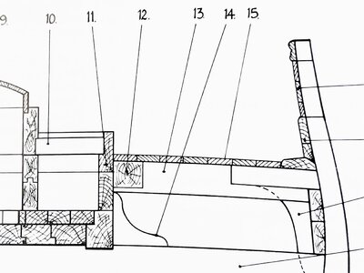
In the Goodwin book we know this cross section through the mortar
View attachment 350953
On the left side we can see the cross section of the waterway (edge to the planking in the same height) - slightly different on the right side where the edge is higher than the planking
View attachment 350952 View attachment 350951
another cross section showing a waterway similar to the right on above
View attachment 350950
But definitely (as usual) the waterway is made from an appr. double height wooden board than the normal planking
Therefore I decided to make my waterways in scratch using some thicker pear wood - also to produce some color difference compared to the planking
Using the kit parts as templates
View attachment 350947
after some minutes with the scroll saw
View attachment 350948
The first working step is done
View attachment 350949
Now the inclinations have to be sanded, the outer form adjusted and the treenails to be made ..... step by step
Many Thanks for your interest .... to be continued ....
-

Win a Free Custom Engraved Brass Coin!!!
As a way to introduce our brass coins to the community, we will raffle off a free coin during the month of August. Follow link ABOVE for instructions for entering.
-

PRE-ORDER SHIPS IN SCALE TODAY!
The beloved Ships in Scale Magazine is back and charting a new course for 2026!
Discover new skills, new techniques, and new inspirations in every issue.
NOTE THAT OUR FIRST ISSUE WILL BE JAN/FEB 2026
You are using an out of date browser. It may not display this or other websites correctly.
You should upgrade or use an alternative browser.
You should upgrade or use an alternative browser.
HMS GRANADO - full hull - POF kit by CAF in 1:48 - by Uwe
- Joined
- Oct 15, 2017
- Messages
- 1,191
- Points
- 443

It is obvious that the saying "form follows function" is a principle in practice long before its origin in 19th century architecture. Very evident in a ship's waterway, which have their shape because of the function they perform, draining excess water from a ship's deck.
I really appreciate those modelers who take on additional work to make their model more accurate in those details where a viewer's trained eye would notice. Nicely done!
I really appreciate those modelers who take on additional work to make their model more accurate in those details where a viewer's trained eye would notice. Nicely done!
- Joined
- Apr 20, 2020
- Messages
- 6,257
- Points
- 738

wonderful work my friend, It's looks beautifulBefore I can finalize the walls and deck of the after cabin I have to make the inner planking
and before I can make the inner planking I have to finalize the waterway(s) on which the planking / spirketing is laying ..... so
one of the next working steps will be the waterway(s)
The kit offers the waterway segments on the sheet with the laser cut planking boards
Using these parts from the kit with the first fitting test
View attachment 350944
The form fitts well (curvatur and also the joints
View attachment 350945
View attachment 350946
But ......
the waterway elements of the kit have off course the smae thickness like the deck planking (coming from the same sheet)
In the Goodwin book we know this cross section through the mortar
View attachment 350953
On the left side we can see the cross section of the waterway (edge to the planking in the same height) - slightly different on the right side where the edge is higher than the planking
View attachment 350952 View attachment 350951
another cross section showing a waterway similar to the right on above
View attachment 350950
But definitely (as usual) the waterway is made from an appr. double height wooden board than the normal planking
Therefore I decided to make my waterways in scratch using some thicker pear wood - also to produce some color difference compared to the planking
Using the kit parts as templates
View attachment 350947
after some minutes with the scroll saw
View attachment 350948
The first working step is done
View attachment 350949
Now the inclinations have to be sanded, the outer form adjusted and the treenails to be made ..... step by step
Many Thanks for your interest .... to be continued ....
Nice added details, those scratch waterways, Uwe.Before I can finalize the walls and deck of the after cabin I have to make the inner planking
and before I can make the inner planking I have to finalize the waterway(s) on which the planking / spirketing is laying ..... so
one of the next working steps will be the waterway(s)
The kit offers the waterway segments on the sheet with the laser cut planking boards
Using these parts from the kit with the first fitting test
View attachment 350944
The form fitts well (curvatur and also the joints
View attachment 350945
View attachment 350946
But ......
the waterway elements of the kit have off course the smae thickness like the deck planking (coming from the same sheet)
In the Goodwin book we know this cross section through the mortar
View attachment 350953
On the left side we can see the cross section of the waterway (edge to the planking in the same height) - slightly different on the right side where the edge is higher than the planking
View attachment 350952 View attachment 350951
another cross section showing a waterway similar to the right on above
View attachment 350950
But definitely (as usual) the waterway is made from an appr. double height wooden board than the normal planking
Therefore I decided to make my waterways in scratch using some thicker pear wood - also to produce some color difference compared to the planking
Using the kit parts as templates
View attachment 350947
after some minutes with the scroll saw
View attachment 350948
The first working step is done
View attachment 350949
Now the inclinations have to be sanded, the outer form adjusted and the treenails to be made ..... step by step
Many Thanks for your interest .... to be continued ....
Regards, Peter
Bonjour, y a t il une raison particulière pour laquelle vous avez utilisé des clous en cuivre au lieu de clou en laiton que l'on trouve plus facilement dans le commerce ?Many Thanks to @Mirek , @shota70 , @Tobias , @Hoss6262 and @Cathber for the kind comments and all others for the given likes / thumb upps
usually the small copper nails have 0,6 or sometimes 0,7mm diameter - predrilling of pilotholes is a must, although the timber of this kit are very good and splintering is extremely unlikely. I pre-drill with 0,5mm, so that the nail is slightly pressed into the wood, therefore no glue necessary.
Hello, is there a particular reason why you used copper nails instead of brass nails which are more easily found on the market ?
Many Thanks to @Philski , @Hoss6262 , @shota70, @Peter Voogt and @Cathber for your kind comments and your interest
and off cozurse all other for the likes received - much appreciated
A small technical advantage of copper compared to brass is the fact, that this metal is slightly softer than brass, so easier to sand smoothe with the surface. A small disadvantage of the softness is, that using a hammer sometimes they bent faster - so pre-drilling is important.
But most important for me is the final appearance of the nail head after some time.
brass is shiny and will stay shiny - brass is reflecting the light
copper is darkening after some time so that the nail heads or better pseudo-bolts are with some time not so noticeable any more
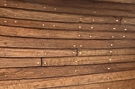
As an example you can see here the "copper-nailed" hull planking of my Le Coureur, clinker build
and off cozurse all other for the likes received - much appreciated
Simple answer - I like the appearance much more compared to brass nailsHello, is there a particular reason why you used copper nails instead of brass nails which are more easily found on the market ?
A small technical advantage of copper compared to brass is the fact, that this metal is slightly softer than brass, so easier to sand smoothe with the surface. A small disadvantage of the softness is, that using a hammer sometimes they bent faster - so pre-drilling is important.
But most important for me is the final appearance of the nail head after some time.
brass is shiny and will stay shiny - brass is reflecting the light
copper is darkening after some time so that the nail heads or better pseudo-bolts are with some time not so noticeable any more
As an example you can see here the "copper-nailed" hull planking of my Le Coureur, clinker build

Merci pour votre réponse, je consulte fréquemment votre journal de construction du HMS Granado avec grand intérêt car je vais peut être me lancer sur cette construction.Many Thanks to @Philski , @Hoss6262 , @shota70, @Peter Voogt and @Cathber for your kind comments and your interest
and off cozurse all other for the likes received - much appreciated
Simple answer - I like the appearance much more compared to brass nails
A small technical advantage of copper compared to brass is the fact, that this metal is slightly softer than brass, so easier to sand smoothe with the surface. A small disadvantage of the softness is, that using a hammer sometimes they bent faster - so pre-drilling is important.
But most important for me is the final appearance of the nail head after some time.
brass is shiny and will stay shiny - brass is reflecting the light
copper is darkening after some time so that the nail heads or better pseudo-bolts are with some time not so noticeable any more
As an example you can see here the "copper-nailed" hull planking of my Le Coureur, clinker build
View attachment 351732
Félicitation pour votre travail, c'est super et cela donne envie de se lancer.
Encore une question d'amateur. Avec le temps, les clous en cuivre ne risque -t-il pas de se patiner et de prendre une couleur en vert (corrosion du cuivre) ?
Thank you for your response, I frequently check your HMS Granado build log with great interest as I may be getting into this build.
Congratulations on your work, it's great and it makes you want to get started.
Another amateur question. Over time, aren't the copper nails likely to patina and take on a green color (copper corrosion) ?
they are getting darker and dull - and no green color caused by copper oxidation or copper rustMerci pour votre réponse, je consulte fréquemment votre journal de construction du HMS Granado avec grand intérêt car je vais peut être me lancer sur cette construction.
Félicitation pour votre travail, c'est super et cela donne envie de se lancer.
Encore une question d'amateur. Avec le temps, les clous en cuivre ne risque -t-il pas de se patiner et de prendre une couleur en vert (corrosion du cuivre) ?
Thank you for your response, I frequently check your HMS Granado build log with great interest as I may be getting into this build.
Congratulations on your work, it's great and it makes you want to get started.
Another amateur question. Over time, aren't the copper nails likely to patina and take on a green color (copper corrosion) ?
I am not sure, but I think you need water for such an oxidation (like at the liberty statue)
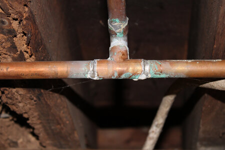
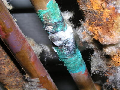
the nail heads have such a dark red-brown color .....
- Joined
- Aug 8, 2019
- Messages
- 5,585
- Points
- 738

The green discoloration is caused by salts and ammonia vapors. You can reproduce this on a quick way at home by rub the copper with wet salt and put it in a plastic bag and a bowl of ammonia. Close the bag (blow air in it so the plastic bag stays blistered.) Leave this for 24 hours and your copper pieces will be green like Uwek's pictures.Over time, aren't the copper nails likely to patina and take on a green color (copper corrosion) ?
Many Thanks for the additional information.The green discoloration is caused by salts and ammonia vapors. You can reproduce this on a quick way at home by rub the copper with wet salt and put it in a plastic bag and a bowl of ammonia. Close the bag (blow air in it so the plastic bag stays blistered.) Leave this for 24 hours and your copper pieces will be green like Uwek's pictures.
So if you would like to have a coppered hull with green oxidation -> but it in a bag etc....
Did somebody tried this already? If yes, please post the experience
Going further with the waterways
Also the waterway-plank is fixed with treenails towards the deck beams
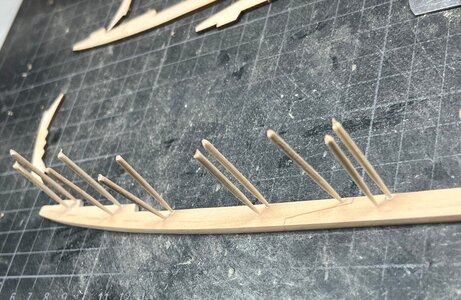
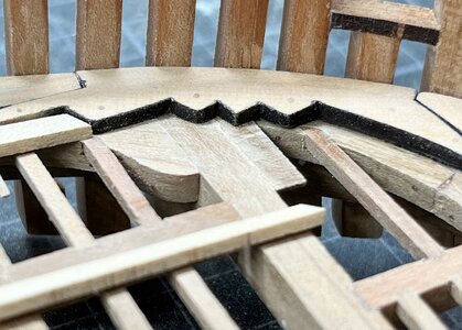
The flat scarf joint is faked - only with a sharp knife cut into the waterway - later on with some black color it will look like a caulked joint
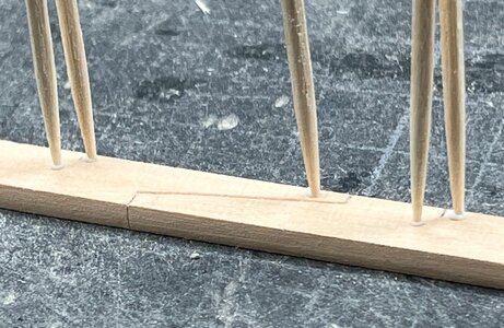
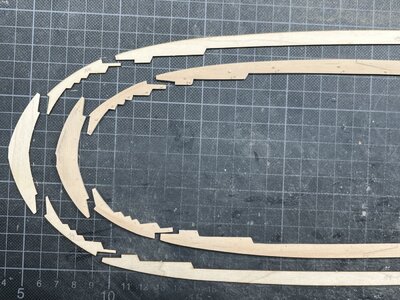
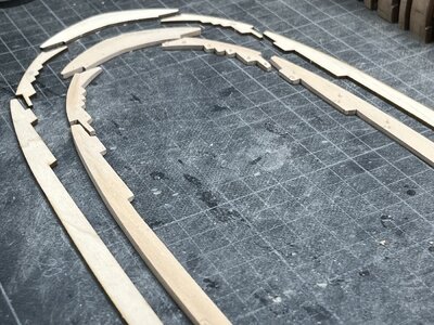
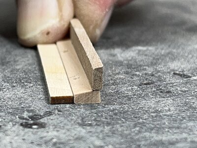
The cross section of the waterway
A first trial with the deck planking to get a firt feeling og how it will look like
During installation some smaller adjustment will be necessary in order to remove the small gaps (you can see, that I mixed already the planking, so that now grain line will move from one plank over to the neighbour plank
Many Thanks for your interest .... to be continued .....
Also the waterway-plank is fixed with treenails towards the deck beams

The flat scarf joint is faked - only with a sharp knife cut into the waterway - later on with some black color it will look like a caulked joint


The cross section of the waterway

A first trial with the deck planking to get a firt feeling og how it will look like

During installation some smaller adjustment will be necessary in order to remove the small gaps (you can see, that I mixed already the planking, so that now grain line will move from one plank over to the neighbour plank

Many Thanks for your interest .... to be continued .....
Nice to see the process of making the nibbling planks and waterways, Uwe.Going further with the waterways
Also the waterway-plank is fixed with treenails towards the deck beams
View attachment 351949
The flat scarf joint is faked - only with a sharp knife cut into the waterway - later on with some black color it will look like a caulked joint
View attachment 351950
View attachment 351953
View attachment 351954
The cross section of the waterway
View attachment 351955
A first trial with the deck planking to get a firt feeling og how it will look like
View attachment 351951
During installation some smaller adjustment will be necessary in order to remove the small gaps (you can see, that I mixed already the planking, so that now grain line will move from one plank over to the neighbour plank
View attachment 351952
Many Thanks for your interest .... to be continued .....
Regards, Peter
- Joined
- Jan 9, 2020
- Messages
- 10,566
- Points
- 938

Good preparatory work for the nibbing Uwe. I have a question though: When you make the adjustments to the bow end on the planks that do not fit nicely into the waterway now, (it looks like you will have to increase their angles), will the plank not end up being too short towards the midships area?
Many Thanks to @Peter Voogt , @Heinrich and @Nomad for the comments and all the likes received
Also easier possible, because we have a deck with a step in between - these planks shown in the posts are ending at the wall towards the after cabin
All together we have several decks and levels in the ship

dark green - main deck
light green - after cabin deck
purple - after cabin floor
dark blue - several small decks in the hold
on midship between the two mortar beds are no decks in the hold
so back to @Heinrich question:
we are talking about the drak green deck - and the planking is longer than the edge towards the cabin wall -> adjustments at the bow are possible without any bigger problems with length
In addition, if this would be not case:
I will follow as much as possible the planking pattern shown in the Anatomy book from Peter Goodwin
and
I will plank only approximately half of the deck - the other side will be without planking, so that the structure with beams, carlings, knees is visible.
(refering also to @Nomad ´s comment)
The kit is providing deck planking for the complete deck area - and the laser cut planking is mirrored along the ships axis
So with partially shortening the planks to get the joints (four shift pattern), and the double material for only half of the deck planking, I will have enough material
Not at all - CAF prepared the preshaped planking in such a way, that all of them are longer than needed.When you make the adjustments to the bow end on the planks that do not fit nicely into the waterway now, (it looks like you will have to increase their angles), will the plank not end up being too short towards the midships area?
Also easier possible, because we have a deck with a step in between - these planks shown in the posts are ending at the wall towards the after cabin
All together we have several decks and levels in the ship

dark green - main deck
light green - after cabin deck
purple - after cabin floor
dark blue - several small decks in the hold
on midship between the two mortar beds are no decks in the hold
so back to @Heinrich question:
we are talking about the drak green deck - and the planking is longer than the edge towards the cabin wall -> adjustments at the bow are possible without any bigger problems with length
In addition, if this would be not case:
I will follow as much as possible the planking pattern shown in the Anatomy book from Peter Goodwin
and
I will plank only approximately half of the deck - the other side will be without planking, so that the structure with beams, carlings, knees is visible.
(refering also to @Nomad ´s comment)

The kit is providing deck planking for the complete deck area - and the laser cut planking is mirrored along the ships axis
So with partially shortening the planks to get the joints (four shift pattern), and the double material for only half of the deck planking, I will have enough material
- Joined
- Jan 9, 2020
- Messages
- 10,566
- Points
- 938

That is all good then - no need for concern. Thank you for the reply, Uwe.Many Thanks to @Peter Voogt , @Heinrich and @Nomad for the comments and all the likes received
Not at all - CAF prepared the preshaped planking in such a way, that all of them are longer than needed.
Also easier possible, because we have a deck with a step in between - these planks shown in the posts are ending at the wall towards the after cabin
All together we have several decks and levels in the ship
View attachment 352128
dark green - main deck
light green - after cabin deck
purple - after cabin floor
dark blue - several small decks in the hold
on midship between the two mortar beds are no decks in the hold
so back to @Heinrich question:
we are talking about the drak green deck - and the planking is longer than the edge towards the cabin wall -> adjustments at the bow are possible without any bigger problems with length
In addition, if this would be not case:
I will follow as much as possible the planking pattern shown in the Anatomy book from Peter Goodwin
and
I will plank only approximately half of the deck - the other side will be without planking, so that the structure with beams, carlings, knees is visible.
(refering also to @Nomad ´s comment)
View attachment 352129
The kit is providing deck planking for the complete deck area - and the laser cut planking is mirrored along the ships axis
So with partially shortening the planks to get the joints (four shift pattern), and the double material for only half of the deck planking, I will have enough material
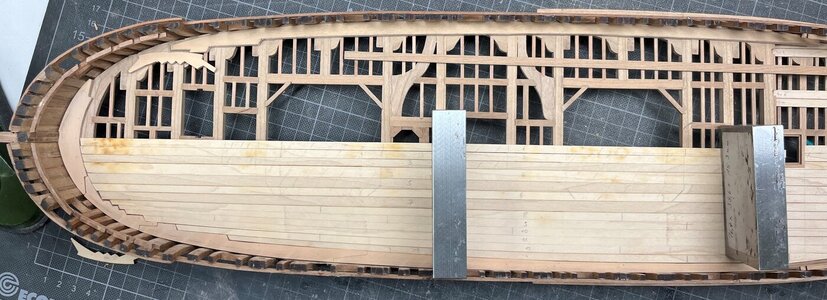
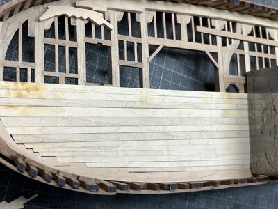
Starting with the adjustments of the deck planking
with cutting into reasonable lengths to produce the butt joints - everytime on top a beam - locations of the butt joints are similar like in Goodwins book
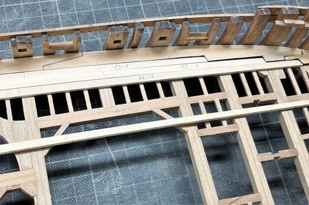
also the contact areas of the planks with the waterway have to be corrected
the edges of the waterway are painted black (with Ecoline black) to simulate the caulking
the fake joints in the waterway were also painted with Ecoline
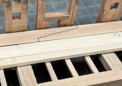
Each planking row (in the kit included one plank over the complete length) was divided into 2 or 3 single planks in order to reach the planking pattern of Goodwins deck drawing
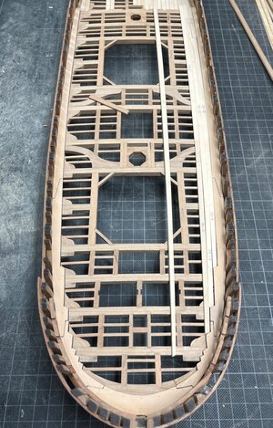
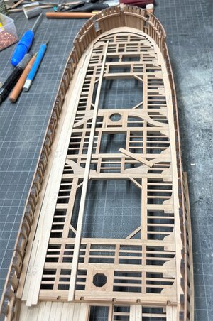
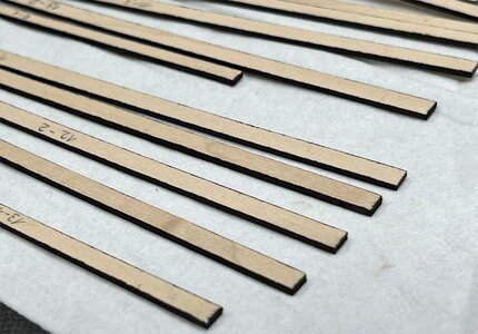
after all the necessary adjustments of the planks I painted the edges of the planks also with black Ecoline pencils
and placed
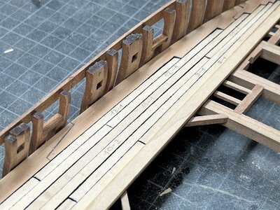
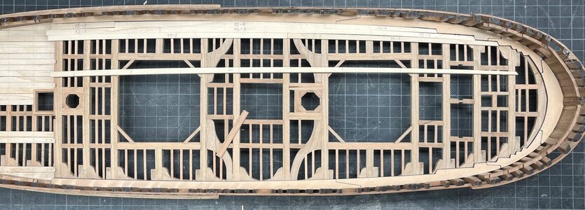
The last wider plank (row 7 kings-plank) is not prepared until now.
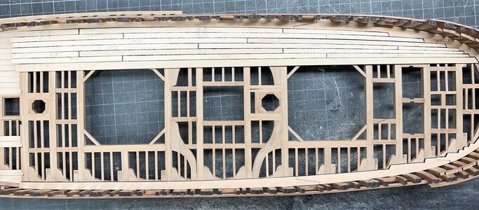
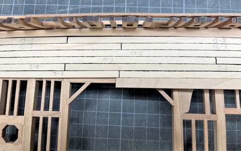
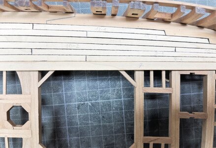
Planking rows 13 to 8 are already fixed to the beams
Planking row 7 is an oversized (in width) plank, which has to be adjusted in width to fitt well to the mortar box walls.
Very clever idea by CAF, with this the modeler has the chance to adjust the deckplanking to his real situation with his model and to cover some inaccuracies in his work
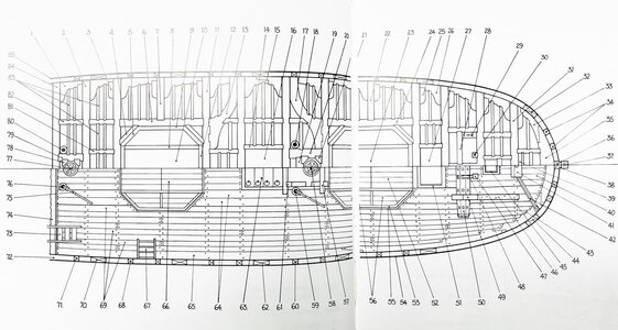
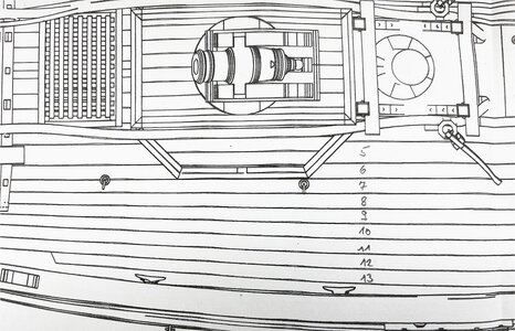
The CAF sketch in the manual - row 7 is marked in red
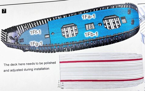
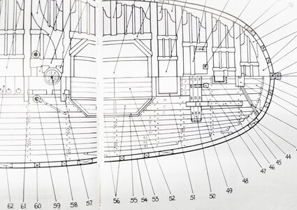
Excerpt of Goodwin´s deck drawing
Excerpt of CAF´s deck drawing
Many Thanks to your interest in my work on the Granado - highly appreciated - to be continued
with cutting into reasonable lengths to produce the butt joints - everytime on top a beam - locations of the butt joints are similar like in Goodwins book

also the contact areas of the planks with the waterway have to be corrected

the edges of the waterway are painted black (with Ecoline black) to simulate the caulking

the fake joints in the waterway were also painted with Ecoline

Each planking row (in the kit included one plank over the complete length) was divided into 2 or 3 single planks in order to reach the planking pattern of Goodwins deck drawing


after all the necessary adjustments of the planks I painted the edges of the planks also with black Ecoline pencils

and placed

The last wider plank (row 7 kings-plank) is not prepared until now.

Planking rows 13 to 8 are already fixed to the beams
Planking row 7 is an oversized (in width) plank, which has to be adjusted in width to fitt well to the mortar box walls.
Very clever idea by CAF, with this the modeler has the chance to adjust the deckplanking to his real situation with his model and to cover some inaccuracies in his work


The CAF sketch in the manual - row 7 is marked in red

Excerpt of Goodwin´s deck drawing

Excerpt of CAF´s deck drawing

Many Thanks to your interest in my work on the Granado - highly appreciated - to be continued
Hallo Uwe, looks very nice as always, cleanly finished and absolutely informative. Einfach Klasse.
Wonderful Uwe. I'm always learning something new from you.
Many thanks to all the comments and the likes received - much appreciated
Some days ago I explained the plank #7 which is oversized, better has a oversized width and also bordered directly to the mortar box.
In order to define the correct width over the length it is necessary as a next step to prepare the box of the mortar, minumum the box walls.
(plank 7 is located over the beam marked with 12)
so for a short interruption I prepared the box
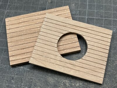
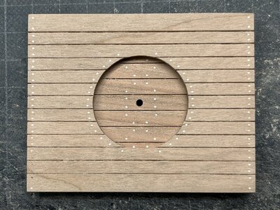
so first the floor of the mortar box - once more two sizes of copper-"bolts"
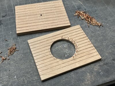
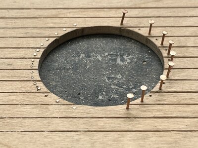
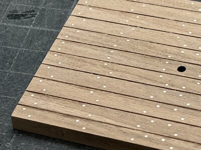
the center hole is the truning center of the mortar
The two layers of wooden beams will be founded on the mortar bed structure
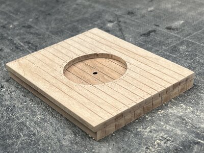
unfortunately I made no photos of making the box walls
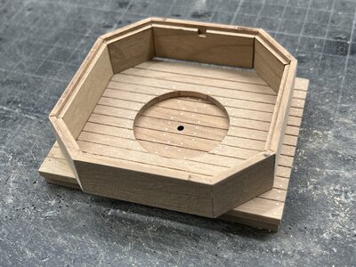
and a fast dry fit in the deck structure
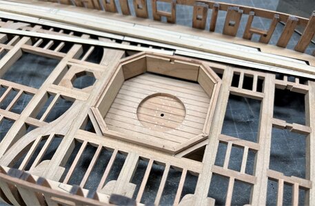
Now I can go further with the deck planking
Many Thanks for the interest in my building log .... to be continued .....
Some days ago I explained the plank #7 which is oversized, better has a oversized width and also bordered directly to the mortar box.
In order to define the correct width over the length it is necessary as a next step to prepare the box of the mortar, minumum the box walls.
(plank 7 is located over the beam marked with 12)

so for a short interruption I prepared the box
so first the floor of the mortar box - once more two sizes of copper-"bolts"


the center hole is the truning center of the mortar

The two layers of wooden beams will be founded on the mortar bed structure

unfortunately I made no photos of making the box walls

and a fast dry fit in the deck structure

Now I can go further with the deck planking
Many Thanks for the interest in my building log .... to be continued .....


