-

Win a Free Custom Engraved Brass Coin!!!
As a way to introduce our brass coins to the community, we will raffle off a free coin during the month of August. Follow link ABOVE for instructions for entering.
-

PRE-ORDER SHIPS IN SCALE TODAY!
The beloved Ships in Scale Magazine is back and charting a new course for 2026!
Discover new skills, new techniques, and new inspirations in every issue.
NOTE THAT OUR FIRST ISSUE WILL BE JAN/FEB 2026
You are using an out of date browser. It may not display this or other websites correctly.
You should upgrade or use an alternative browser.
You should upgrade or use an alternative browser.
HMS GRANADO - full hull - POF kit by CAF in 1:48 - by Uwe
I do not think, that this is the main reason. I have another hypothesis about the shield.I would assume the shield on front of chimney exhaust is to keep things from falling in?
This chimney has a square cross section, so it was not possible to rotate with the direction of the wind.
I think the shield was installed, that, during the ship was not sailing or on anchor, the wind coming from fore would not press the smoke backwards into the chimney....
Many Thanks to @pianoforte , @GrantTyler , @shota70 , @Kurt Konrath , @AnobiumPunctatum , @dockattner , @Nomad , @Bryian , @Mirek , @Tobias and @Hoss6262 for your kind comments and replies and all others for the likes received - Much appreciated
The next progress photos will come soon ..... Many Thanks for your interest
Looks great Uwe! 
Beautiful impressions, very nicely done, great pictures.
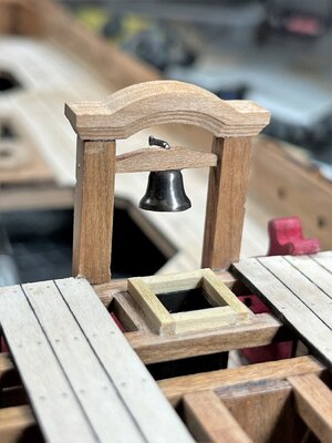
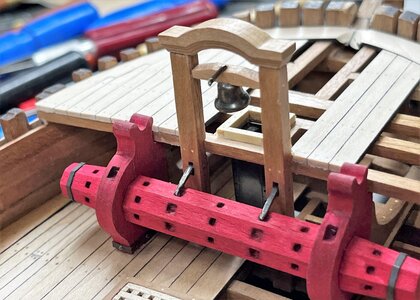
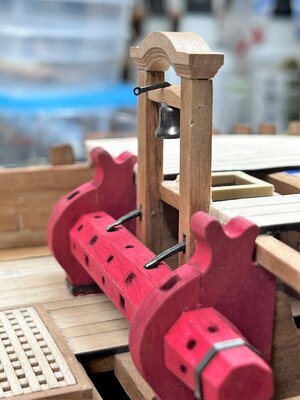
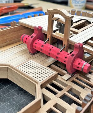
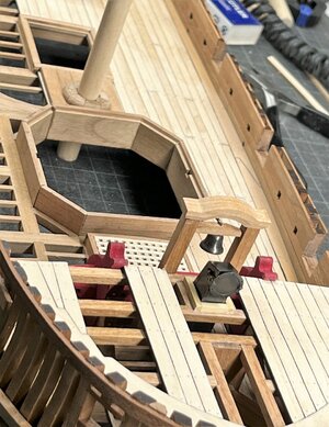
Uwe, I didn’t think you needed to talk about how the bars were located on the rooster gratesOne of the most important parts of a ship was installed - the ships bell
View attachment 379405
View attachment 379404
View attachment 379406
View attachment 379408
View attachment 379409
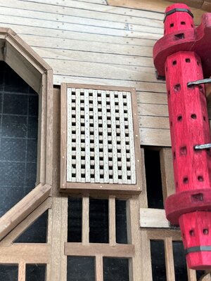
and also finished the hatch with grating between the windlass and the first mortar bed
View attachment 379407
Many Thanks for your interest ..... to be continued .....
- Joined
- Jun 17, 2021
- Messages
- 3,203
- Points
- 588

Yikes! Uwe! Oh my goodness! 


Pete


Pete
Love the grating! Weren’t the ships bells used to signal different things like shift changes, meals, etc.?
- Joined
- Aug 14, 2018
- Messages
- 829
- Points
- 403

Hi Uwek,
I really love the clean, accurate work you do and this build of the Granado is a real tribute to your skills. For my information could you help me out with the orientation of the ships gratings, I noticed that the grating in your photographs of the bell tower has the ledges running fore and aft and the battens set into them across ship. this is very pleasing to the eye in gratings that are short and wide as this one is but I understood that the battens should always run fore and aft or does this not matter?
Kind regards Jack.
Many Thanks to @Mirek , @pianoforte , @Alexander74 , @Nomad , @Peter Gutterman , @Dean62 , @Jack Jäger for your kind comments, hints and replies and all others for the likes received - much appreciated
As you know, I try not to leave any question open, so I try to explain my thoughts here related to the direction of the battens and ledges of the grating.
Somehow, in general you are right @Alexander74 and @Jack Jäger , but ..... often there is a "but"
Let us summarize:
1) This grating is the only grating of a hatch on this model - it is wider than long
2) Very informative information and also the sketch confirming your information you can find f.e. here
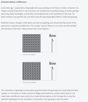

 shipmodeler.wordpress.com
3) Also Gérard Delacroix confirmed this for french ships

=> This would mean, that I am wrong with my "directions" of ledges and cross battens
4) Once in the past I searched a little bit and found most of the gratings and information confirming it, but I also found several examples on real ships, where the gratings were different - I took examples of relatively small coamings
confirming the usual opinion (when you look at the direction of the deck planking)
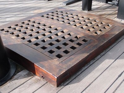
different
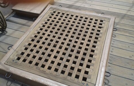
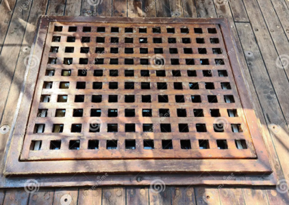
=> Like some of you know, I am a civil engineer so I was thinking about the statical aspect of such a grating
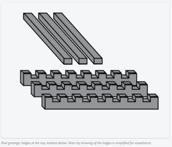
The cross battens are laying on top of the ledges - which means that the forces of any weight are transfered to the two ends of the ledges
I show here the direction of the forces with red arrows
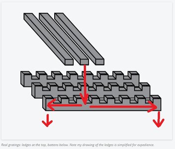
=> based on this I would make the ledges as short as possible! (simple from statical point of view, and to reduce the material weight as much as possible, because than you can reduce the cross sections of ledges and battens)
So I think, that for bigger sized gratings the general rule like you described is correct
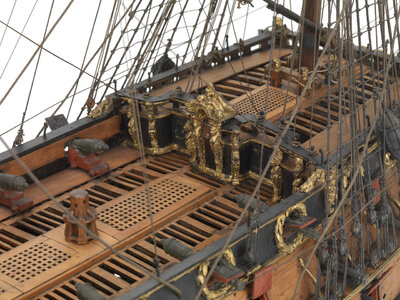
For short gratings where the width is bigger or much bigger than the length, I think the direction could be also different
As you know, I try not to leave any question open, so I try to explain my thoughts here related to the direction of the battens and ledges of the grating.
Somehow, in general you are right @Alexander74 and @Jack Jäger , but ..... often there is a "but"
Let us summarize:
1) This grating is the only grating of a hatch on this model - it is wider than long
2) Very informative information and also the sketch confirming your information you can find f.e. here


Improving Basic Details – Getting the Gratings Right
Gratings are common a feature seen on old ships, as they can be used in place of hatch covers to allow ventilation below decks. They’re also be useful for standing on to keep out of pooling w…
 shipmodeler.wordpress.com
3) Also Gérard Delacroix confirmed this for french ships

=> This would mean, that I am wrong with my "directions" of ledges and cross battens
4) Once in the past I searched a little bit and found most of the gratings and information confirming it, but I also found several examples on real ships, where the gratings were different - I took examples of relatively small coamings
confirming the usual opinion (when you look at the direction of the deck planking)

different


=> Like some of you know, I am a civil engineer so I was thinking about the statical aspect of such a grating

The cross battens are laying on top of the ledges - which means that the forces of any weight are transfered to the two ends of the ledges
I show here the direction of the forces with red arrows

=> based on this I would make the ledges as short as possible! (simple from statical point of view, and to reduce the material weight as much as possible, because than you can reduce the cross sections of ledges and battens)
So I think, that for bigger sized gratings the general rule like you described is correct

For short gratings where the width is bigger or much bigger than the length, I think the direction could be also different
- Joined
- Aug 14, 2018
- Messages
- 829
- Points
- 403

Fair argument Uwek, but since the battens are usually very thin relative to the ledges (1/3 or less), would that not negate any strength advantage in them being laid athwartships? However at the end of the day it is for you to decide and I have to agree with you the grating looks far better the way you have it. Respect. Cheers JJ..Many Thanks to @Mirek , @pianoforte , @Alexander74 , @Nomad , @Peter Gutterman , @Dean62 , @Jack Jäger for your kind comments, hints and replies and all others for the likes received - much appreciated
As you know, I try not to leave any question open, so I try to explain my thoughts here related to the direction of the battens and ledges of the grating.
Somehow, in general you are right @Alexander74 and @Jack Jäger , but ..... often there is a "but"
Let us summarize:
1) This grating is the only grating of a hatch on this model - it is wider than long
2) Very informative information and also the sketch confirming your information you can find f.e. here
View attachment 379723

Improving Basic Details – Getting the Gratings Right
Gratings are common a feature seen on old ships, as they can be used in place of hatch covers to allow ventilation below decks. They’re also be useful for standing on to keep out of pooling w…shipmodeler.wordpress.com
3) Also Gérard Delacroix confirmed this for french ships
View attachment 379724
=> This would mean, that I am wrong with my "directions" of ledges and cross battens
4) Once in the past I searched a little bit and found most of the gratings and information confirming it, but I also found several examples on real ships, where the gratings were different - I took examples of relatively small coamings
confirming the usual opinion (when you look at the direction of the deck planking)
View attachment 379726
different
View attachment 379725 View attachment 379727
=> Like some of you know, I am a civil engineer so I was thinking about the statical aspect of such a grating
View attachment 379728
The cross battens are laying on top of the ledges - which means that the forces of any weight are transfered to the two ends of the ledges
I show here the direction of the forces with red arrows
View attachment 379729
=> based on this I would make the ledges as short as possible! (simple from statical point of view, and to reduce the material weight as much as possible, because than you can reduce the cross sections of ledges and battens)
So I think, that for bigger sized gratings the general rule like you described is correct
View attachment 379730
For short gratings where the width is bigger or much bigger than the length, I think the direction could be also different
Hi Uwe, I work in Engineering, and I have to agree with you that the ends would support the load. However, once you nail the cross battens to the lower battens and support their ends, , then the uppers help with the bending moment on the longer lower battens and they too would load share. So in your example above, lets say you put 200 lbs on the lower battens shown (3), that would be 33.3 lbs per end. Once the cross battens are placed as structural supports (7), you would now have 20 total ends supporting the weight, thus reducing the load to 10 lbs per end. I am not trying to be rhetorical, because I know that you already know this, I am saying it for the benefit of others. And to make this point, once they are all attached to one another then they load share and act as one piece, at which point the orientation no longer matters, only how many ends there are to support the load.Many Thanks to @Mirek , @pianoforte , @Alexander74 , @Nomad , @Peter Gutterman , @Dean62 , @Jack Jäger for your kind comments, hints and replies and all others for the likes received - much appreciated
As you know, I try not to leave any question open, so I try to explain my thoughts here related to the direction of the battens and ledges of the grating.
Somehow, in general you are right @Alexander74 and @Jack Jäger , but ..... often there is a "but"
Let us summarize:
1) This grating is the only grating of a hatch on this model - it is wider than long
2) Very informative information and also the sketch confirming your information you can find f.e. here
View attachment 379723

Improving Basic Details – Getting the Gratings Right
Gratings are common a feature seen on old ships, as they can be used in place of hatch covers to allow ventilation below decks. They’re also be useful for standing on to keep out of pooling w…shipmodeler.wordpress.com
3) Also Gérard Delacroix confirmed this for french ships
View attachment 379724
=> This would mean, that I am wrong with my "directions" of ledges and cross battens
4) Once in the past I searched a little bit and found most of the gratings and information confirming it, but I also found several examples on real ships, where the gratings were different - I took examples of relatively small coamings
confirming the usual opinion (when you look at the direction of the deck planking)
View attachment 379726
different
View attachment 379725 View attachment 379727
=> Like some of you know, I am a civil engineer so I was thinking about the statical aspect of such a grating
View attachment 379728
The cross battens are laying on top of the ledges - which means that the forces of any weight are transfered to the two ends of the ledges
I show here the direction of the forces with red arrows
View attachment 379729
=> based on this I would make the ledges as short as possible! (simple from statical point of view, and to reduce the material weight as much as possible, because than you can reduce the cross sections of ledges and battens)
So I think, that for bigger sized gratings the general rule like you described is correct
View attachment 379730
For short gratings where the width is bigger or much bigger than the length, I think the direction could be also different
ps - Also note the notches are in the lower supports, not the uppers.
Last edited:
Uwek, good day. About the load is logical and understandable. But what was the purpose of the rooster gratings? Close the opening in the deck so that no one accidentally falls and ventilation of the lower decks. The maximum load, as far as I understand, is the weight of the sailor, therefore the cells of the rooster are only 3 inches so that the heel does not fall through. The photographs of the gratings you cited are all "remakes" of replica ships. It is not worth using them as the ultimate truth, because it is not true. I did not see in the documents that the upper rails of the rooster gratings were across the deck, only along. Yes, your grille is beautiful and well made, but I’m sorry, I can’t accept your arguments in favor of the rails acrossMany Thanks to @Mirek , @pianoforte , @Alexander74 , @Nomad , @Peter Gutterman , @Dean62 , @Jack Jäger for your kind comments, hints and replies and all others for the likes received - much appreciated
As you know, I try not to leave any question open, so I try to explain my thoughts here related to the direction of the battens and ledges of the grating.
Somehow, in general you are right @Alexander74 and @Jack Jäger , but ..... often there is a "but"
Let us summarize:
1) This grating is the only grating of a hatch on this model - it is wider than long
2) Very informative information and also the sketch confirming your information you can find f.e. here
View attachment 379723

Improving Basic Details – Getting the Gratings Right
Gratings are common a feature seen on old ships, as they can be used in place of hatch covers to allow ventilation below decks. They’re also be useful for standing on to keep out of pooling w…shipmodeler.wordpress.com
3) Also Gérard Delacroix confirmed this for french ships
View attachment 379724
=> This would mean, that I am wrong with my "directions" of ledges and cross battens
4) Once in the past I searched a little bit and found most of the gratings and information confirming it, but I also found several examples on real ships, where the gratings were different - I took examples of relatively small coamings
confirming the usual opinion (when you look at the direction of the deck planking)
View attachment 379726
different
View attachment 379725 View attachment 379727
=> Like some of you know, I am a civil engineer so I was thinking about the statical aspect of such a grating
View attachment 379728
The cross battens are laying on top of the ledges - which means that the forces of any weight are transfered to the two ends of the ledges
I show here the direction of the forces with red arrows
View attachment 379729
=> based on this I would make the ledges as short as possible! (simple from statical point of view, and to reduce the material weight as much as possible, because than you can reduce the cross sections of ledges and battens)
So I think, that for bigger sized gratings the general rule like you described is correct
View attachment 379730
For short gratings where the width is bigger or much bigger than the length, I think the direction could be also different
Many Thanks to all your comments and the given information - I have to think and make some more researching in publications I have
-> I will try to find the real final answer for me ...... in moment I will leave the grating like it is
In the meantime also the planking of the forecastle is finished (the planking is poarallel - looks only disorianted by the camera angle)
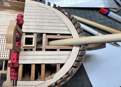
and also the bowsprit dummy was slightly adjusted
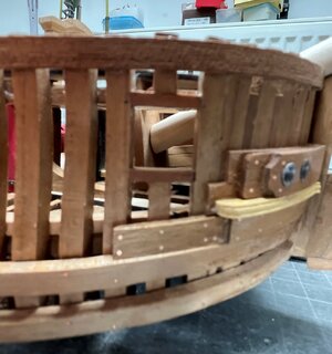
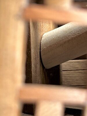
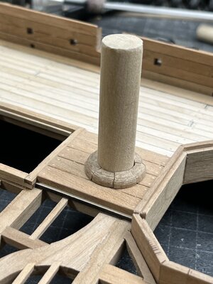
the other hatches were fixed on the deck and the partners and wedges were finalized with the correct size of mast-stumps
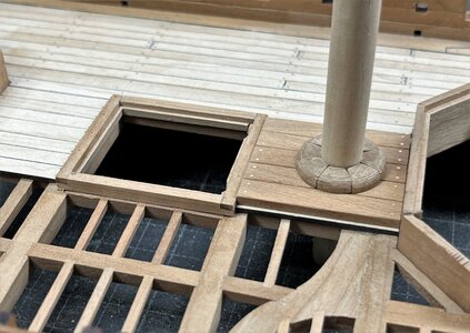
the eyebolts for the hatch cover boards are still missing
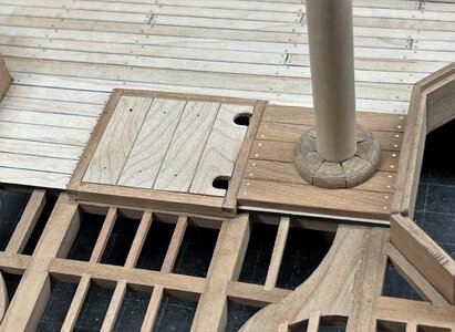
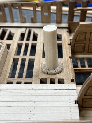
and the view from downside
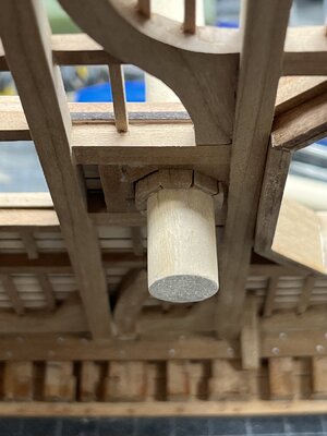
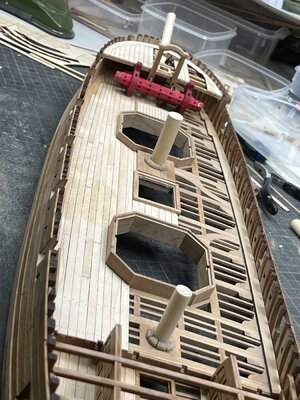
Many Thanks for your interest - I am open for comments, critics and hints ..... to be continued
-> I will try to find the real final answer for me ...... in moment I will leave the grating like it is
In the meantime also the planking of the forecastle is finished (the planking is poarallel - looks only disorianted by the camera angle)

and also the bowsprit dummy was slightly adjusted


the other hatches were fixed on the deck and the partners and wedges were finalized with the correct size of mast-stumps


the eyebolts for the hatch cover boards are still missing


and the view from downside


Many Thanks for your interest - I am open for comments, critics and hints ..... to be continued
Good evening Uwek. Wow- just wow. Cheers GrantMany Thanks to all your comments and the given information - I have to think and make some more researching in publications I have
-> I will try to find the real final answer for me ...... in moment I will leave the grating like it is
In the meantime also the planking of the forecastle is finished (the planking is poarallel - looks only disorianted by the camera angle)
View attachment 380330
and also the bowsprit dummy was slightly adjusted
View attachment 380331
View attachment 380332
the other hatches were fixed on the deck and the partners and wedges were finalized with the correct size of mast-stumps
View attachment 380328
View attachment 380333
the eyebolts for the hatch cover boards are still missing
View attachment 380329
View attachment 380335
and the view from downside
View attachment 380334
View attachment 380336
Many Thanks for your interest - I am open for comments, critics and hints ..... to be continued
Uwe, This is just splendid to follow. I always had a great appreciation for your constant and thoughtful research. And ultimately, POF construction is where I want to focus my attentions. You are an Artisan my friend!
- Joined
- Jan 21, 2022
- Messages
- 891
- Points
- 403

For me, it's more of an instruction with pictures. So the hints go from youMany Thanks for your interest - I am open for comments, critics and hints ..... to be continued


