-

Win a Free Custom Engraved Brass Coin!!!
As a way to introduce our brass coins to the community, we will raffle off a free coin during the month of August. Follow link ABOVE for instructions for entering.
-

PRE-ORDER SHIPS IN SCALE TODAY!
The beloved Ships in Scale Magazine is back and charting a new course for 2026!
Discover new skills, new techniques, and new inspirations in every issue.
NOTE THAT OUR FIRST ISSUE WILL BE JAN/FEB 2026
You are using an out of date browser. It may not display this or other websites correctly.
You should upgrade or use an alternative browser.
You should upgrade or use an alternative browser.
HMS GRANADO - full hull - POF kit by CAF in 1:48 - by Uwe
YesGreat craftsmanship Uwek. Did you use the Ecoline between the deck planks? Cheers
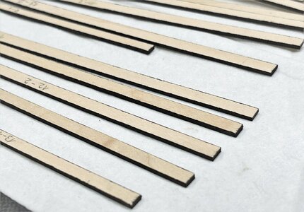
both sides of the individual plank were painted with black Ecoline - with no glue at the contact areas.
The planking strips were fixed with glue only downwards with the beams
Many Thanks to @GrantTyler , @Mirek , @Bill Hime , @WojtasS , @Lucian29 and @Nomad for the kind words and interest, and also to everybody for the given likes
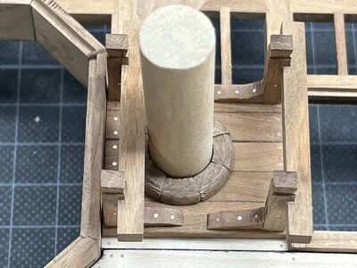
The main mast bitts were prepared
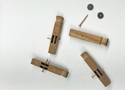
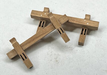
good that these bitts have to be fixed on top of the additional boards of the mast partners, so it can be preared completely and removed afterwards not to damage them
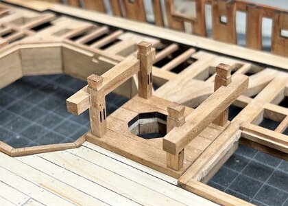
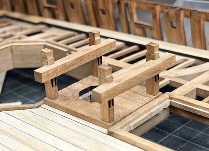
the small knees also fixed - final sanding after the "bolts" are installed (still some laser char visible)
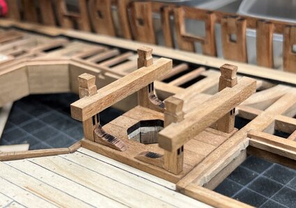
more or less finished with temporary arrangment with mast and wedges
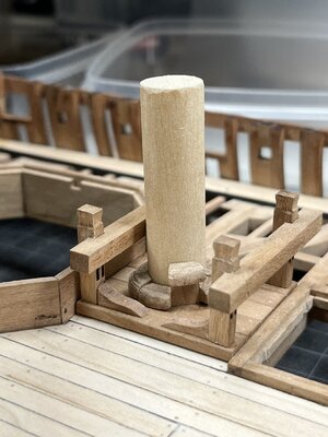
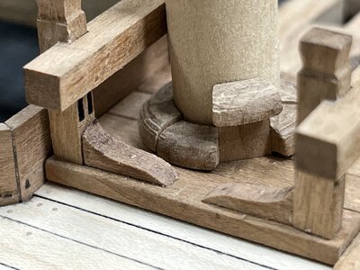
Many Thanks for the interest in my work on the CAF HMS Granado .... much appreciated .... to be continued .....
The main mast bitts were prepared


good that these bitts have to be fixed on top of the additional boards of the mast partners, so it can be preared completely and removed afterwards not to damage them


the small knees also fixed - final sanding after the "bolts" are installed (still some laser char visible)

more or less finished with temporary arrangment with mast and wedges


Many Thanks for the interest in my work on the CAF HMS Granado .... much appreciated .... to be continued .....
Such nice work Uwe!
You produce such excellent workmanship Uwe. There is always so much that can be learnt from your wonderful build and the photographs.
Uwe,
It's good to be back and viewing your pristine workmanship, and many others at SOS. It's great to have the extended shipwright family to follow and participate in my recent retirement. Thanks for all you do!
VR,
Danno
It's good to be back and viewing your pristine workmanship, and many others at SOS. It's great to have the extended shipwright family to follow and participate in my recent retirement. Thanks for all you do!
VR,
Danno
- Joined
- Jan 31, 2021
- Messages
- 570
- Points
- 353

Beautiful work!some small more progress with installing the small beams etc.
View attachment 377021
The bowsprit is a dummy only to get a feeling
View attachment 377022
View attachment 377023
View attachment 377024
View attachment 377025
View attachment 377026
View attachment 377027
View attachment 377028
View attachment 377029
View attachment 377030
Many Thanks for your interest - to be continued .....
I am open for all comments and hints, negative and positiv - especially also related to the question of the hawse holes (which are already drilled off course
Very fine, very precise, very good, very Uwe.
Hallo @Lucian29That sure looks like the real deal. Great work
The mast wedges were kept in place with some means or were just...wedged
sorry for the late reply, I was on a busianess trip over the weekend and had no chance to be online.
These wedges were really only wedged down and prodced the press forces against the mast and against the so called partners
on this photo you can see the "partners" - the wooden elements between the two deck beams
you can see also the gap (here too small and has to be widened) between the partners and the mast
The opening is often an octagon, so it can take over 8 wedges
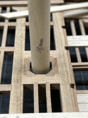
the very rough (not at all sanded) wedges around the mast (8 wedges)
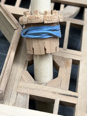
with the deck planking - but be aware, that the wedges are wedged towards the partners and not the planking
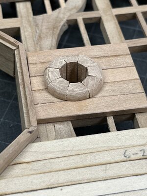
the 8 weddges from bellow without mast
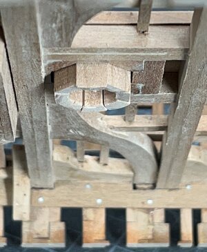
with some adjustments of the thickness of the wedges, the mast angle was able to be slightly adjusted
so f.e. some thicker fore and thinner aft wedges , the mast would get a more inclination / rake towards aft - somehow finetuning of the sailing qualities
these topics can be also somehow interesting:
odd question?
What is the name of the round piece that goes at the base of the mast to cover voids and get a snug fit? and where can I find various sizes.? Thank you.
shipsofscale.com
MAST COLLARS
When a mast passed through an upper deck, logically a collar was present to prevent/ reduce the entry of sea water to the lower decks. Did lower decks have collars as well ? Pete
shipsofscale.com
Kurt Konrath
Kurt Konrath
On real ships I know the mast wedges were driven in to help hold and align the mast, but were they then cleaned up to look nice and even as often seen or just left uneven and rough?? Trying to learn the difference in real ship and model building.Many Thanks to @GrantTyler , @Mirek , @Bill Hime , @WojtasS , @Lucian29 and @Nomad for the kind words and interest, and also to everybody for the given likes
The main mast bitts were prepared
View attachment 380824
View attachment 380825
good that these bitts have to be fixed on top of the additional boards of the mast partners, so it can be preared completely and removed afterwards not to damage them
View attachment 380826
View attachment 380827
the small knees also fixed - final sanding after the "bolts" are installed (still some laser char visible)
View attachment 380828
more or less finished with temporary arrangment with mast and wedges
View attachment 380829
View attachment 380830
View attachment 380831
Many Thanks for the interest in my work on the CAF HMS Granado .... much appreciated .... to be continued .....
Hallo Kurt,On real ships I know the mast wedges were driven in to help hold and align the mast, but were they then cleaned up to look nice and even as often seen or just left uneven and rough?? Trying to learn the difference in real ship and model building.
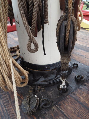
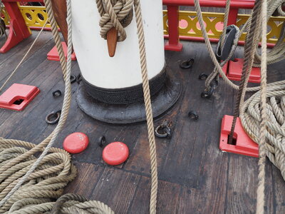
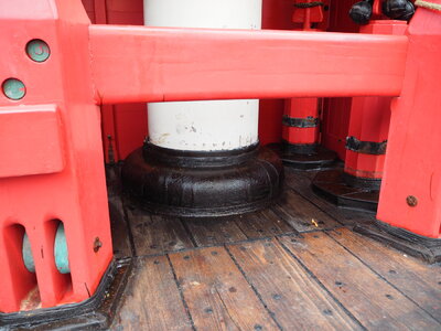
yes, on sailing vessels like ours, they were correctly shaped and afterwards covered with some canvas and tarred to protect them from moisture and making the deck on this part watertight. Imagine what could happen when the wood of the wedges and / or mast would rot - immense danger for the ship
Here are some examples, originally posted by @Thomas Marocke
Hi Uwe. You have added some very nice details around the mast with those wedged. Time consuming but with a great appearance.Hallo @Lucian29
sorry for the late reply, I was on a busianess trip over the weekend and had no chance to be online.
These wedges were really only wedged down and prodced the press forces against the mast and against the so called partners
on this photo you can see the "partners" - the wooden elements between the two deck beams
you can see also the gap (here too small and has to be widened) between the partners and the mast
The opening is often an octagon, so it can take over 8 wedges
View attachment 381539
the very rough (not at all sanded) wedges around the mast (8 wedges)
View attachment 381540
with the deck planking - but be aware, that the wedges are wedged towards the partners and not the planking
View attachment 381541
the 8 weddges from bellow without mast
View attachment 381542
with some adjustments of the thickness of the wedges, the mast angle was able to be slightly adjusted
so f.e. some thicker fore and thinner aft wedges , the mast would get a more inclination / rake towards aft - somehow finetuning of the sailing qualities
these topics can be also somehow interesting:
odd question?
What is the name of the round piece that goes at the base of the mast to cover voids and get a snug fit? and where can I find various sizes.? Thank you.shipsofscale.comMAST COLLARS
When a mast passed through an upper deck, logically a collar was present to prevent/ reduce the entry of sea water to the lower decks. Did lower decks have collars as well ? Peteshipsofscale.com
Regards, Peter
Many Thanks to all for your kind comments and likes - and the intire interest in my building log
highly appreciated and a big motivation to procede with the work on the model and making regular posts showing the small working progress
The upper part of the model has still the two open areas for the two mortars - so the next working step will be the mortar beds and also the mortars
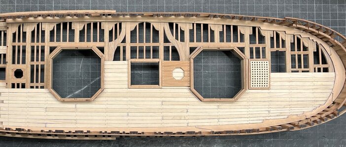
(photo is showing an older status of progress)
already in January I made the first wooden floor of one of the mortar boxes
so I will not show in detail the second one
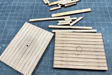
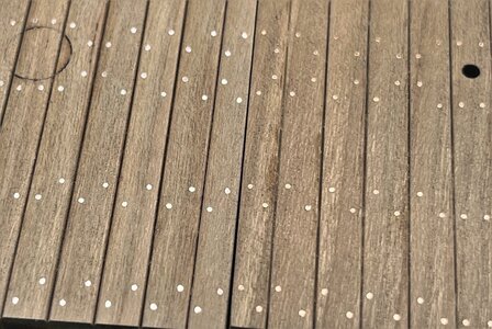
after nailing the second floor with copper bolts I made this photo -> on the right side the older one from January and on the left the new one.
If you take a close look at the bolts you can see already the difference in the color of the nails - copper is getting darker with the time -> because of this behaviour I like copper more than brass for immitating bolt heads
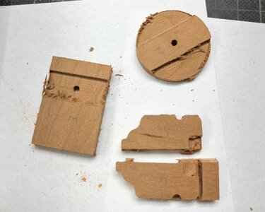
some main elements of the mortar carriages are cnc-milled
In one of the contemporary drawings the mortars are shown
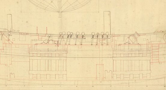
not completely visible, but we know from other documents, that the Granado had two different sizes of mortars
one 10" and a bigger 13" mortars (see here also the information given in threedecks)
CAF is supplying with the kit exactly these two different types of mortars, so historical absolutely correct - In the caldercraft kit the mortars are identical
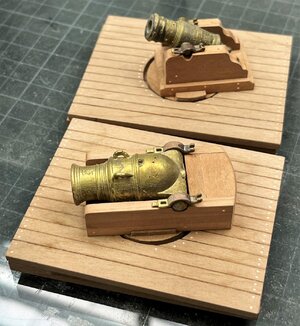
after some cleaning the two different mortar carriages (on the left the 10", on the right the 13")
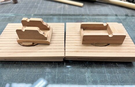
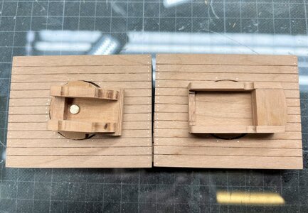
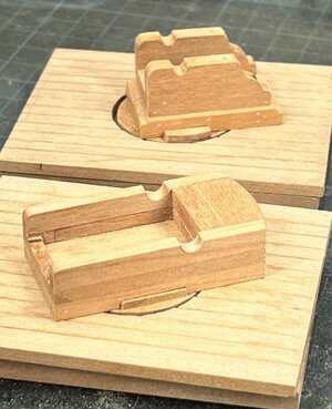
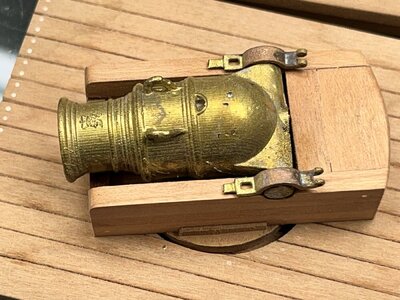
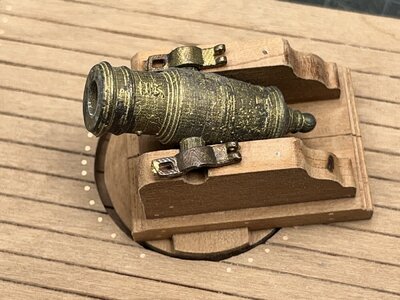
I could not resist to put the uncleaned muzzles temporary on the carriages and you can see the difference
the 13" mortar
an the 10" mortar
to be continued ......
highly appreciated and a big motivation to procede with the work on the model and making regular posts showing the small working progress
The upper part of the model has still the two open areas for the two mortars - so the next working step will be the mortar beds and also the mortars

(photo is showing an older status of progress)
already in January I made the first wooden floor of one of the mortar boxes
HMS GRANADO - full hull - POF kit by CAF in 1:48 - by Uwe
Before I can finalize the walls and deck of the after cabin I have to make the inner planking and before I can make the inner planking I have to finalize the waterway(s) on which the planking / spirketing is laying ..... so one of the next working steps will be the waterway(s) The kit offers...
shipsofscale.com
so I will not show in detail the second one

after nailing the second floor with copper bolts I made this photo -> on the right side the older one from January and on the left the new one.
If you take a close look at the bolts you can see already the difference in the color of the nails - copper is getting darker with the time -> because of this behaviour I like copper more than brass for immitating bolt heads

some main elements of the mortar carriages are cnc-milled

In one of the contemporary drawings the mortars are shown

not completely visible, but we know from other documents, that the Granado had two different sizes of mortars
one 10" and a bigger 13" mortars (see here also the information given in threedecks)
CAF is supplying with the kit exactly these two different types of mortars, so historical absolutely correct - In the caldercraft kit the mortars are identical
after some cleaning the two different mortar carriages (on the left the 10", on the right the 13")


I could not resist to put the uncleaned muzzles temporary on the carriages and you can see the difference

the 13" mortar

an the 10" mortar

to be continued ......


