HMS GRANADO - full hull - POF kit by CAF in 1:48 - by Uwe

Many Many Thanks for all the comments, replies and likes recieved

some body asked some time ago, that it is time to get rid off the sanding blocks -> so here you can find a first try - and it is looking not so bad

A brass tube inside a brass tube - the inner one is located in a drilled hole inside the frame - the outer tube is keeping the distance

View attachment 452600

View attachment 452595

View attachment 452598

all together only three tubes

View attachment 452592

View attachment 452597

View attachment 452601

View attachment 452602

View attachment 452603

It is "A" solution - maybe the final one .....

many thanks for your interest .... to be continued .....

View attachment 452599
That’s a very nice presentation with the 3 brass tubes, Uwe.
PS: Please secure the right aft tube on top in it’s hole ……. ;)
Regards, Peter
 
Last edited:
PS: Please secure the right aft tube on top in it’s hole ……. ;)
Hallo Peter,
I have to make these brass tubes removable for the future transports of the (hopefully once finished) model- and will take care to hit the holes correctly.

Which diameter do you have choosen? If possible I would go with thinner brass tubes.
To be honest - In moment I do not know exactly - I took some brass tubes which I had in my stock
In future I will try with some thinner one - but at the end they have to be stabile enough - once finished there will be appr. 1,5 or 2kg weight on top of these 3 tubes
 
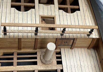
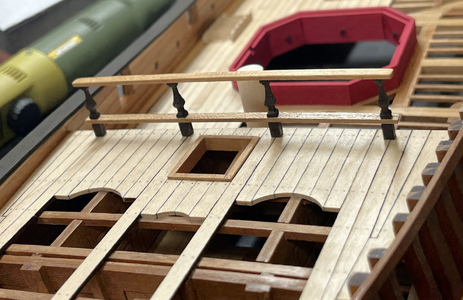
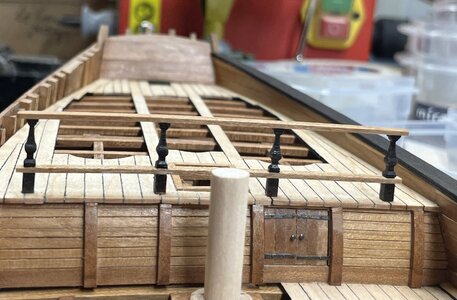
Unfortunately I did not make any photos during the production, but I have some nice of the finished balustrade

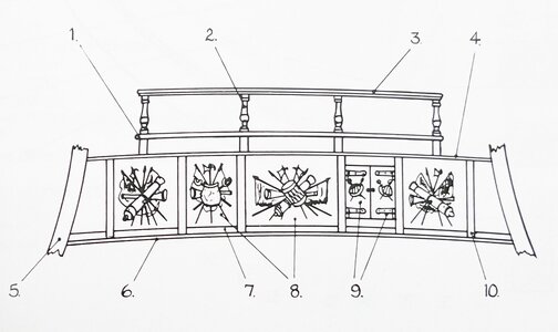
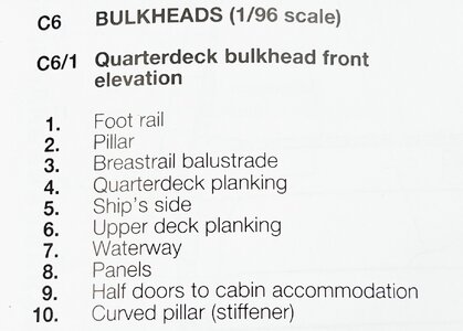
These are Goodwins interpretation

IMG_1894.jpg IMG_1897.jpg

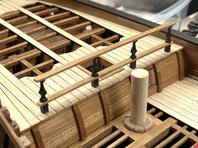
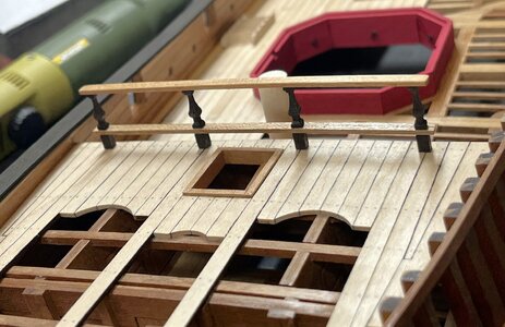
and the result on my model

IMG_4852.jpg

IMG_4849.jpg

IMG_4850.jpg

in the moment only temporary fixed with some pins in each pillar

IMG_4851.jpg

Many Thanks for your interest in my log .... to be continued .....
 
Hi Uwek,
I like the nice clean lines you have achieved on your model. This means more speed less haste. Which means slow down to do it properly the first time in English. Nice work and something I will try to aspire to once I start the Bounty. Lots of those lines are achieved in the Model Makers toolshop. So, I guess to reach that standard, I will need to make lots of jigs to do only one thing.
I was wondering if I may be able to do similar as what you have because the Bounty was a unique vessel in that it had a Greenhouse under its deck and it would be, and I hope I can achieve a lift-up part of the deck to show the Greenery.
A lot of holes will need to be drilled, 600 odd holes but achievable.
 
Unfortunately I did not make any photos during the production, but I have some nice of the finished balustrade

These are Goodwins interpretation

View attachment 453263 View attachment 453264

and the result on my model

View attachment 453262

View attachment 453259

View attachment 453260

in the moment only temporary fixed with some pins in each pillar

View attachment 453261

Many Thanks for your interest in my log .... to be continued .....
A nice balustrade, Uwe. It’s looking nice by the open deck parts.
Regards, Peter
 
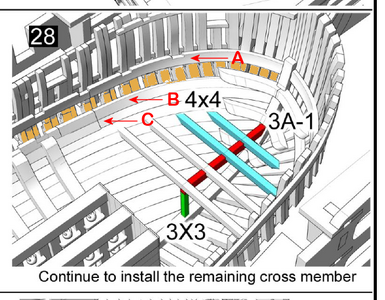
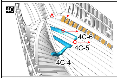
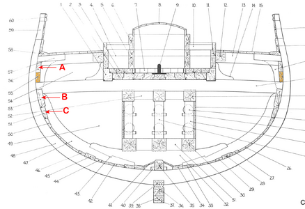
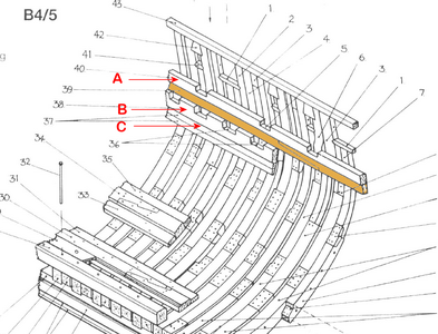
I'm not sure this is visible on your split model (at least without turning the top portion upside-down), but should there be planking between the Upper Deck Clamp (or Beam Shelf) (part 'A' in the kit) and the Mortar Pit Beam Shelf (part 'B' in the kit), rather than having exposed frames in these areas? This area is shown in tan that I've added to the kit instructions:
1718764687430.png
It is about 10mm high for most of the hull length, but gets wider towards aft:
1718764747259.png
MUCH wider, in fact, depending on how the planking is applied by the builder.

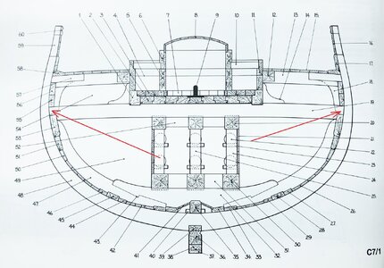
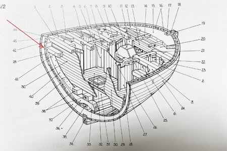
I believe, per the Goodwin's plans, this area should be planked. I've again highlighted in tan the area/beam I think is omitted on the following drawings from the book:
1718764857777.png
1718764915901.png
I would think that planking would be required in this area, especially in the Bread Room at the stern, since British ship builders usually took great pains in trying to keep this area dry to prevent spoiling of the hardtack, even to adding removable floor panels and other moisture protection, similar even to what was done in powder magazines (no floor or other panels are included in the model).

Even just from an appearance standpoint (if I am lucky enough to be able to see this area in my completed model), it seems this area, which is adjacent to lower deck cabins and rooms, should be complete and planked.
 
I'm not sure this is visible on your split model (at least without turning the top portion upside-down), but should there be planking between the Upper Deck Clamp (or Beam Shelf) (part 'A' in the kit) and the Mortar Pit Beam Shelf (part 'B' in the kit), rather than having exposed frames in these areas? This area is shown in tan that I've added to the kit instructions:
View attachment 454172
It is about 10mm high for most of the hull length, but gets wider towards aft:
View attachment 454173
MUCH wider, in fact, depending on how the planking is applied by the builder.

I believe, per the Goodwin's plans, this area should be planked. I've again highlighted in tan the area/beam I think is omitted on the following drawings from the book:
View attachment 454174
View attachment 454176
I would think that planking would be required in this area, especially in the Bread Room at the stern, since British ship builders usually took great pains in trying to keep this area dry to prevent spoiling of the hardtack, even to adding removable floor panels and other moisture protection, similar even to what was done in powder magazines (no floor or other panels are included in the model).

Even just from an appearance standpoint (if I am lucky enough to be able to see this area in my completed model), it seems this area, which is adjacent to lower deck cabins and rooms, should be complete and planked.
I would say according to the Anatomy of the Ship book on the Granado, the answer would be yes. Even though if you look on page 50 at diagram B4/5 it looks like there is a space, if you look on page 51 at diagram B5/3, it plainly shows a plank there which would be supporting surface of the hanging knees.
However, this is only one source and I'm without any personal knowledge on this topic.

If someone has different information, I will not be offended if you present it. :)

Jeff
 
Many Many Thanks for all the comments, replies and likes recieved

some body asked some time ago, that it is time to get rid off the sanding blocks -> so here you can find a first try - and it is looking not so bad

A brass tube inside a brass tube - the inner one is located in a drilled hole inside the frame - the outer tube is keeping the distance

View attachment 452600

View attachment 452595

View attachment 452598

all together only three tubes

View attachment 452592

View attachment 452597

View attachment 452601

View attachment 452602

View attachment 452603

It is "A" solution - maybe the final one .....

many thanks for your interest .... to be continued .....

View attachment 452599
Spectacular!
 
I was not making a detailed research and build it like I did at the time with the section.
Also based on the knowledge, that the ships had often the inner planking partly open for ventilation / dehydration of the area between the outer planking and the inner one - remember f.e. the carpenters walkway on bigger vessels

Nevertheless also Goodwin is showing an open area where the inner planking is not complete and has a gap

IMG-8025aaa.jpg IMG_0664.jpg
 
I was not making a detailed research and build it like I did at the time with the section.
Also based on the knowledge, that the ships had often the inner planking partly open for ventilation / dehydration of the area between the outer planking and the inner one - remember f.e. the carpenters walkway on bigger vessels

Nevertheless also Goodwin is showing an open area where the inner planking is not complete and has a gap

View attachment 454390 View attachment 454392
I think he is asking about where #55 is on your C7/1 image, but I could be wrong too. :)
 
Back
Top