AgreedI think so.
-

Win a Free Custom Engraved Brass Coin!!!
As a way to introduce our brass coins to the community, we will raffle off a free coin during the month of August. Follow link ABOVE for instructions for entering.
-

PRE-ORDER SHIPS IN SCALE TODAY!
The beloved Ships in Scale Magazine is back and charting a new course for 2026!
Discover new skills, new techniques, and new inspirations in every issue.
NOTE THAT OUR FIRST ISSUE WILL BE JAN/FEB 2026
You are using an out of date browser. It may not display this or other websites correctly.
You should upgrade or use an alternative browser.
You should upgrade or use an alternative browser.
HMS Sovereign of the Seas - Bashing DeAgostini Beyond Believable Boundaries
- Thread starter DARIVS ARCHITECTVS
- Start date
- Watchers 105
Thanks Bill! The last posts progress took me two days. It goes slowly.Hello Kurt,
You are doing beautiful work.
Bill
- Joined
- Aug 8, 2019
- Messages
- 5,582
- Points
- 738

To much paint maybe.if that means anything.
Well, there you go! Thanks Vic!!!!I don’t see any treenails on the closeup of the painted Victory, if that means anything. View attachment 339466
Planning and inserting drop planks.
Slowly bringing the lines of the final planking in parallel with those of the first planking, except that the joinery and angles of the final planking are made accurate to planking style of the period. The narrow width of the planks and lack of spiling in most areas resulted in a larger number of drop planks than normal, especially near the bow. That is because I'm not as experienced as other model builders. The overall effect still looks nice.
Install the drop plank where two planks diverge. In this case, the drop plank was installed between the loose plank on top and the previously glued plank below it. Another divergence point was created about 7cm aft of the drop plank joint we just made, and another drop plank will be inserted there.
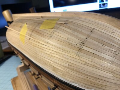
Marking the next drop plank on the opposite side of the hull, inserting it where the pencil marking indicates. Wood will be cut away from the upper plank with the cut on the pencil line.
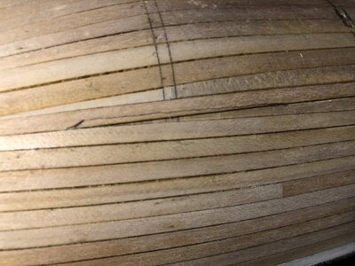
Slowly bringing the lines of the final planking in parallel with those of the first planking, except that the joinery and angles of the final planking are made accurate to planking style of the period. The narrow width of the planks and lack of spiling in most areas resulted in a larger number of drop planks than normal, especially near the bow. That is because I'm not as experienced as other model builders. The overall effect still looks nice.
Install the drop plank where two planks diverge. In this case, the drop plank was installed between the loose plank on top and the previously glued plank below it. Another divergence point was created about 7cm aft of the drop plank joint we just made, and another drop plank will be inserted there.

Marking the next drop plank on the opposite side of the hull, inserting it where the pencil marking indicates. Wood will be cut away from the upper plank with the cut on the pencil line.

Last edited:
Indeed, it does Kurt. Looking at your very fine detail description of the process, I will bookmark this portion of your build and will defiantly incorporate it in my next build.The overall effect still looks nice.
I haven't gone in to any detail in to how the location of drop planks are decided upon, or how important it is to do the planks in pairs, port and starboard, and take occasional measurements of the edge of the creeping plank layer from the keel or bottom wale, in order to preserve symmetry. A model looks better with symmetrical drop plank and stealer locations, but in reality for ships of this early time, I believe the availability of timbers of the required shape was the predominant factor in deciding where the plank seams actually go. If you look at the decks of the Wasa, you can see that what we think should be even and symmetrical deck planking lines is far from what they actually did. Planks went where they fit, and that's that. Precise symmetry was the sort of workmanship which developed later until it became almost an art form. Of course, some ships are built with more precision and care than others, and each ship of this time was completely unique. Small variations in symmetry on my hull are due to my lack of precision, not from intent on historical accuracy with regard to planking style. In other words, I'm building the model with SOME historical information and the rest is educated guesswork, with some completely wild guesses thrown in if there are no other options. Every bit of information on this ship is gathered, considered, and chosen among choices. It's not up to the skill level of those builders making POF models carefully milled out of pearwood, but it's a far cry from the simple kit build I originally planned due to the enormous amount I've learned from many sources, and that includes you guys.Indeed, it does Kurt. Looking at your very fine detail description of the process, I will bookmark this portion of your build and will defiantly incorporate it in my next build.

Last edited:
I was looking at your post #1448, the ninth picture down (being worth a thousand words) actually speaks volumes to me as far as method and proceedure.I haven't gone in to any detail in to how the location of drop planks are decided upon
I have seen the example of that method a few times in photos but did not understand how to choose the location for those lost strakes until I studied your post.
A big thank you for that post.
Anytime. Glad you got something helpful out of it!I was looking at your post #1448, the ninth picture down (being worth a thousand words) actually speaks volumes to me as far as method and proceedure.
I have seen the example of that method a few times in photos but did not understand how to choose the location for those lost strakes until I studied your post.
A big thank you for that post.
Continuing from last post, the bow, narrowing at the left, needs drop planks to fill the expanding gap as you go to the right. The pencil line shows the next cut in the upper plank where two planks diverge. Wedge tipped drop planks (Dutch style) are much easier to using in planning the planking pattern than English style arrowhead tipped drop planks.
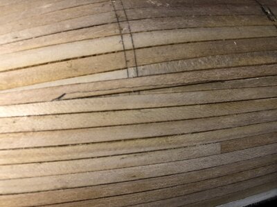
After cutting, the upper plank which is loose has a place to insert a drop plank.
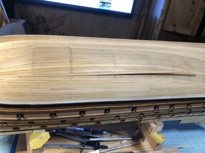
The dashed pencil line shows where the upper plank's edge used to be.
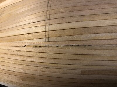
The drop plank is inserted and glued down, along with the upper plank. The loose end of planks are cut to a length corresponding with a frame location, so plank seams line up vertically every other plank or every few planks. You don't want two plank end seams located vertically adjacent to one another.
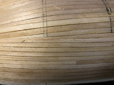
Here is the progress so far. The planking gap is closing slowly, and you want to try to make the edges of the gap more and more parallel as you add planks to narrow the gap. Because the planking gap is generally parallel at my stern, planking the buttocks with correct planking lines will be relatively easy.
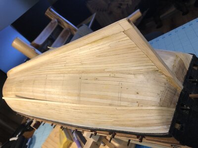
The real challenge for a ship with a bluff bow like this is arranging drop planks to fill the quickly narrowing gap at the stem. If your planks narrow to a width smaller than 1/2 the width of a full width plank, you didn't use enough drop plank. Pointed or needle thin planks are not correct. They leak if you make them on a real hull and are weak in strength. My gap at the stem is getting dangerously narrow, so I'm going to have to plan drop planks carefully to bring the plank lines closer and closer to parallel as you move planks and avoid needle planks at the bow. This is going to be a royal pain in the ass to figure out (as usual).
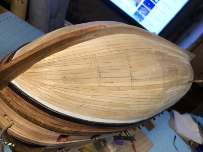

After cutting, the upper plank which is loose has a place to insert a drop plank.

The dashed pencil line shows where the upper plank's edge used to be.

The drop plank is inserted and glued down, along with the upper plank. The loose end of planks are cut to a length corresponding with a frame location, so plank seams line up vertically every other plank or every few planks. You don't want two plank end seams located vertically adjacent to one another.

Here is the progress so far. The planking gap is closing slowly, and you want to try to make the edges of the gap more and more parallel as you add planks to narrow the gap. Because the planking gap is generally parallel at my stern, planking the buttocks with correct planking lines will be relatively easy.

The real challenge for a ship with a bluff bow like this is arranging drop planks to fill the quickly narrowing gap at the stem. If your planks narrow to a width smaller than 1/2 the width of a full width plank, you didn't use enough drop plank. Pointed or needle thin planks are not correct. They leak if you make them on a real hull and are weak in strength. My gap at the stem is getting dangerously narrow, so I'm going to have to plan drop planks carefully to bring the plank lines closer and closer to parallel as you move planks and avoid needle planks at the bow. This is going to be a royal pain in the ass to figure out (as usual).

Seems like a lot of drop planks.
Yeah. Part of that comes from the use of narrow, 4mm wide planks. When you use 5mm planks, the amount of drop planks is less.Seems like a lot of drop planks.
Makes sense.Yeah. Part of that comes from the use of narrow, 4mm wide planks. When you use 5mm planks, the amount of drop planks is less.
The bike I'm on is the Kawasaki F21M 238cc 2-stroke motocross bike. The bike Buck Buchanon (#96) is a Honda CL72 Scrambler 4-stroke. Much heavier. My Kawasaki melted a hole in the piston as they had it jetted way too lean. I was sponsored by Kawasaki....There are 150kg difference - and I am not talking about the biker ......
Last edited:
OUCH. That poor engine.The bike I'm on is the Kawasaki F21M 238cc 2-stroke motocross bike. The bike Buck Buchanon (#96) is a Honda CL72 Scrambler 4-stroke. Much heavier. My Kawasaki melted a hole in the piston as they had it jetted wsy too lean. I was sponsored by Kawasaki....
Progress continues on the final planking of the hull bottom. The puzzle of how to resolve the pattern of merging planks at the bow has been solved. The idea is to anchor new planks with glue at the pointy end of the gap at the stem, and fill the diverging gap as you move aft using drop planks as necessary. I know it;s hard to distinguish the 4mm maple planks on top of the 5mm first layer of basswood planks in the photos because they are nearly the same color.
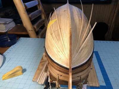
First the gap along the stem was filled and closed off with the ends of tapered planks to complete this area. The formed gaps with the points of acute angles located father aft. These gaps will be filled with drop planks until the overall gap stops diverging about 12cm from the stem, and the gap edges run roughly parallel to each other.
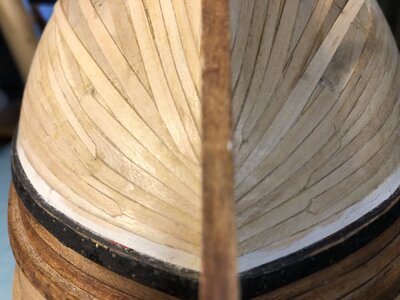
Close=up of the plank ends at the stem. Not perfect, but good enough.
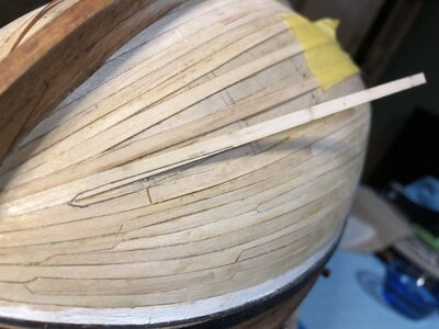
A diverging gap on the starboard side is prepared by tracing out a pre-tapered wood strip onto the existing planks.
Drop planks need to be copied on the port side to match the starboard side.
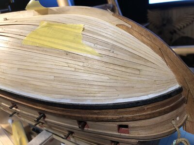
Some more drop planks need to be inserted in the starboard side to fill the narrow gaps between the loose planks that had their ends glued at the bow. The planks, being only glued at the bow, are free to move as they are laid down onto the hull to fill the gap at midships and farther aft.
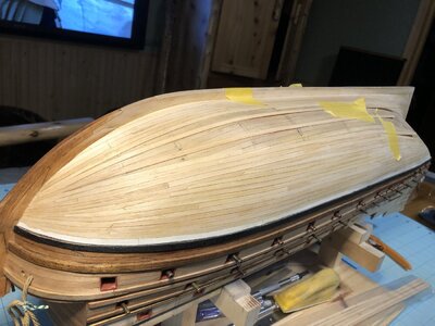
Progress so far on the port side. Now that most of the triangular gap at the bow has been filled, and the rest of the gap is roughly rectangular from there all the way back to the buttocks. planking will become much easier to plan and complete.
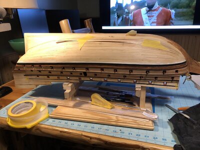
First the gap along the stem was filled and closed off with the ends of tapered planks to complete this area. The formed gaps with the points of acute angles located father aft. These gaps will be filled with drop planks until the overall gap stops diverging about 12cm from the stem, and the gap edges run roughly parallel to each other.

Close=up of the plank ends at the stem. Not perfect, but good enough.

A diverging gap on the starboard side is prepared by tracing out a pre-tapered wood strip onto the existing planks.

Drop planks need to be copied on the port side to match the starboard side.

Some more drop planks need to be inserted in the starboard side to fill the narrow gaps between the loose planks that had their ends glued at the bow. The planks, being only glued at the bow, are free to move as they are laid down onto the hull to fill the gap at midships and farther aft.

Progress so far on the port side. Now that most of the triangular gap at the bow has been filled, and the rest of the gap is roughly rectangular from there all the way back to the buttocks. planking will become much easier to plan and complete.

Good work Kurt.Sovereign's bow is quite an unusual shape that I would describe as " semi bluff ".Not an easy form to plank
Kind Regards
Nigel
Kind Regards
Nigel
Yes, the sharp taper at the bow is a challenge. Your planking arced into the keel long before reaching the stem, and the line of your planks differ largely from mine as a result. Mine ran along the keel and part way up the stem before terminating, which really created a tight pinch point for the plank ends below the bottom wale. The buttocks will turn out better.Good work Kurt.Sovereign's bow is quite an unusual shape that I would describe as " semi bluff ".Not an easy form to plank
Kind Regards
Nigel
Last edited:
Hallo Kurt alias @DARIVS ARCHITECTVSHMS Sovereign of the Seas - Bashing DeAgostini Beyond Believable Boundaries - by DARIVS ARCHITECTVS
Well, I just finished La Couronne and its display case a few hours ago, and swore that I would take a break before starting another project.
That didn't happen. On to Ship #2.
Research on building HMS Sovereign of the Seas started almost immediately. I opened Issues 1-15 of the kit and started pouring through their contents, eager to work on the one ship which is the greatest inspiration above all others. The first problem reared its ugly head immediately. The false keel assembly does not include the keel itself, ending at the garboard strake of planking. I could not use my multi-position keel vice that served my so well while building La Couronne! That meant that the base jig in the DeAgostini instructions has to be built and used. The keel is attached later in assembly, and I'm afraid that it won't be strong enough to use the keel vice, and one accidental bump on the hull will break the keel off, leaving the wrecked hull rolling on the floor. I guess I'll have to be careful.
Some more observations. This model has a complete lower gun deck, unlike Corel's La Couronne, so it will be easy to replace the false half-barrel cannons with complete carriages. (Don't look at me like that, Dockattner... You may take ALL the shortcuts you want! Not THIS sailor.) Because the kit instructions are scattered across 135 packages in magazines, the steps for assembling multiple similar items like cannons are also scattered, and there are no blueprints or rigging drawings to refer to that give you the complete picture of how elements like lines, decorations and other landmarks used in measuring are positioned, relative to each other and the hull overall. This is quite different than working from the two general arrangement drawings and seven rigging drawings that helps you classify and keep track of what you are working on, and where something goes.
Just to get something done, the first frame pieces of the bow were glued together, and some wood metal "L" brackets for making the base jig were purchased. There is still one more piece of wood to purchase before the base jig can be completed and the false keel assembled. Since I wanted to use those GORGEOUS Amati cast decorations on this model, the problem remains whether or not they would fit because the scales between the Amati and DeAgostini models are slightly different. Laying the false keel bulkheads on the Amati plans shows that they may actually be close enough to allow use of most of the Amati decorations. Each decoration, Amati or DeAgostini, will have to be chose based on how close to the Payne description of the decorations they are. Perhaps in some cases neither will work, and scratch built decorations will have to be made, which I do not have the patience, tools or talent to do. Carving is a slow, high risk task for me. Too much can go wrong. After all, I'm an engineer (Architectus in Latin), not an artist.
Many things will be replaced in this white metal casting, plywood ridden, arguably accurate DeAgostini kit. LET THE BASHING BEGIN.
It looks like somebody broke the sprit topmast, or it that just he camera lens effect?
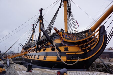
This is NOT what the kit build would look like. This is the scratch built Italian made model that the simplified kit approximates, and falls short of
we wish you all the BEST and a HAPPY BIRTHDAY


