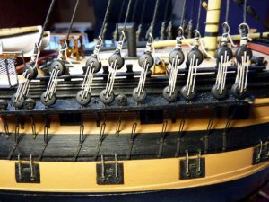
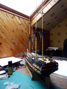
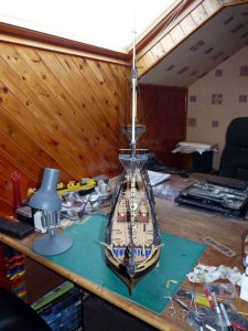
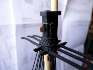
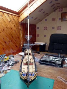
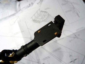
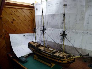
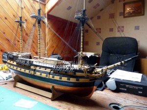
HMS Vanguard 1787 - Victory Models - 1:72 [COMPLETED BUILD]

At this point I decided to assemble the fore mast and the fore top. There were a few things that weren’t clear to me and needed resolving.
• I’d already seen posts saying that the fore mast cap, which is in two pieces, should have a square hole to fit the end of the fore mast rather than a round one.
• I couldn’t make sense of the cross sections of the mast.
• The top section of the mast is square but the diagram shows it to be larger than can be cut from a 10mm dowel.
• There are a number of blocks below the top but it wasn’t clear which were at the front and which at the back
• I didn’t understand the bottom of the fore top mast.

I decided to see what I could do with the cap. I managed to square up the hole to just under 6mm which was less than the dimension of the top of the mast so that seemed a viable solution.
I gave up on the cross section drawings and decided to see how it worked out.
I put the fore top and cross trees together. There’s a bit of play in the joints so I took advantage of this and put the fore and aft pieces as close together as possible. They ended up 8.2mm apart. That meant that when I planed down the sides of the mast, I had to end up at 8.2mm at the point where the cross trees fitted. At the lower end I took off half the thickness of the mast cheeks.
I was getting brave at this point so I glued the hounds to the cheeks and then clamped them to the mast. I could now dry fit the top in place and mark the upper edge of the cross trees.
With that done, I squared off the mast above this point. Theoretically the largest square I could make out of a 10mm dowel is just over 7mm. I opted to make it 7.5mm and accept very slightly rounded corners. At the same time I squared up the section that fitted between the cross trees by trimming the fore and aft sides to bring that down to 8.2mm.
I slightly chamfered the transition between the 8.2mm square section and the 7.5mm one.
The final job was to square up the top section to fit the hole in the cap.

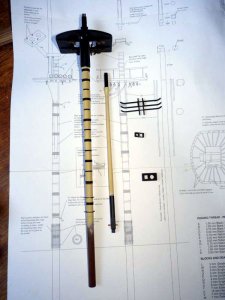
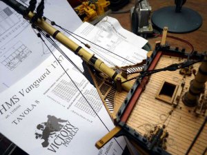
This was my kit of parts at this time:

PICT_V_4101
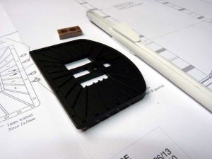
pict_v_4101_.jpg

I should have taken a picture of the mast before I faired in the cheeks and gave it a coat of white primer.

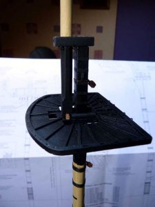
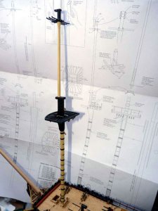
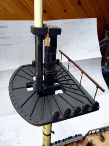
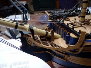
The following pictures show how it fitted together:

PICT_V_4102
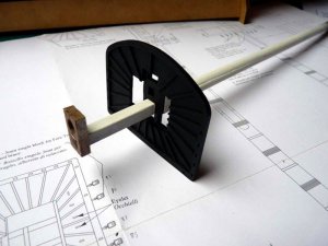
pict_v_4102_.jpg

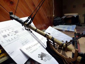
PICT_V_4103
pict_v_4103_.jpg

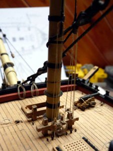
PICT_V_4104
pict_v_4104_.jpg

If you look at the top just in front of the mast, you’ll see I’ve framed the hole that takes the foot of the fore top mast. That mast is 7mm square at the bottom, smaller than the hole in the cross trees. It also has a 5mm long square section at the bottom which seems to be 5mm square. I’ve framed the hole to reduce it to 5mm, but I don’t understand this 5mm piece and think the hole should be 7mm. I thought it was easier to make it smaller at this stage and open it up if required than to frame and paint it later.

As far as the blocks are concerned, all seven of those shown under the top fit on the front cross piece but the outer three on each side are duplicated on the aft cross piece.
(For information those three carry lines 77, 78, 61,62 & 63 reading outwards from the mast.)
The two fiddle blocks shown above the mast are for the lifts and are strapped round the cap.
Note: The fore yard tie cleats seem to be incorrectly named. The fore yard tie goes over the cap at the same place as the two fiddle blocks; the lines above the cleats run to the jeer blocks.

Sorted!
Well, unfortunately not.

The fore topmast is shown as being 2mm from the fore mast, and at the bottom is spaced forward with a 2mm square walnut cross piece. The distance between the centres of the two sections of mast is about 9.2mm. When I dropped a drill bit through the front hole in the cap to see how it lined up, the answer was that it didn’t! It leaned forward quite a lot. When I checked the cap, I found the distance between centres to be 11.2mm.
I’ve now made a new cap!
Here’s how they compare.

PICT_V_4105
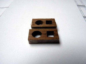
pict_v_4105_.jpg
 
Last edited:
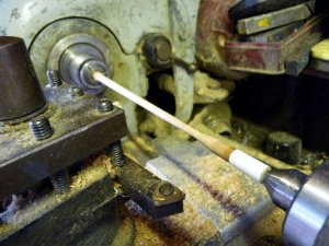
After a major operation to fit a new belt on my lathe, I turned the dowel for the fore topmast to size:

PICT_V_4201
pict_v_4201_.jpg

The top and bottom sections are square but the section just below the cap is octagonal. I opted to shape those by hand. To get the correct size for the top section, I assembled the fore topmast trestle trees and sized it to fit those. It ended up 5.7mm square.
You’re supposed to build up the bottom of the mast to 7mm square (the dowel isn’t big enough to get a full 7mm square out of it) so the octagonal section is also 7mm across flats. I started by squaring up the whole of the bottom section to 7mm with the intention of then taking off the corners to create the octagonal section. However, once I’d done that the corners were only slightly rounded so I decided to see if I could cheat. I tried building up the corners at the bottom, where the mast has to be square, with ordinary filler. It was only a partial success, one of the corners simply came off and another one didn’t look too good. I tried again using some two part wood filler that I had in stock. The hardest bit was getting the tiniest bit of hardener to go with the small amount of filler I needed. It still set pretty rapidly, but it was a great success and I was able to square up the bottom section.

Next job was to fit the various blocks to the fore top.
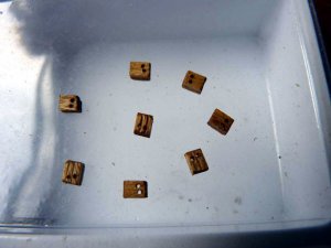
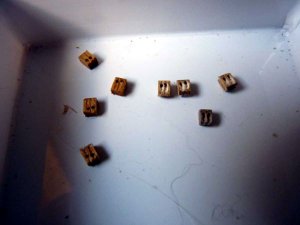
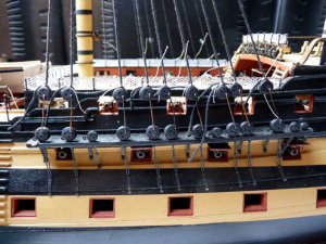
There are eight double 4mm blocks under the top, the ones supplied were some of the worst I’ve ever seen:

PICT_V_4202
pict_v_4202_.jpg

At least they’re more or less out of sight under there so I took the worst four and attempted to make them more respectable. One was beyond redemption as the side was split away at such an angle that one of the holes came out on the edge.
Here’s how they looked, three have been cleaned up and I made a new one to replace the split one; I think they’re passable:

PICT_V_4203
pict_v_4203_.jpg

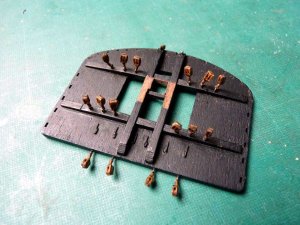
This is how the fore top looked with the blocks in place:

PICT_V_4204
pict_v_4204_.jpg

There’s a row of eyelets across the back. As you can see, I fastened these the same way as the ones fitted in the channels.

Next job was fitting the bands and woldings on the mast. That was a reasonably straightforward job. The upper ring for the boarding pikes has to go on before the bottom wolding though.
To fasten the rings, I drilled three small holes in the mast and pressed in the off-cuts of the eyelets I’d fitted in the fore top (they’re 0.5mm copper). I trimmed them off so that only about 1mm was sticking out and the ring rested on top of those. I then soldered the rings to the pins.
After fitting a few more blocks to the mast, this was my kit of parts:

PICT_V_4205
pict_v_4205_.jpg

There are some blocks to fit on the mast cap but although I’ve glued the two halves together, the rest is dry fitted, The deadeyes and handrail should just push into place.
This is how it fits together:

PICT_V_4206
pict_v_4206_.jpg

This picture of how it looks so far doesn’t really show much, other than the fact it’s suddenly got an awful lot bigger!

PICT_V_4207
pict_v_4207_.jpg

And there’s still another section to go!
 
Last edited:
A little more progress. I’ve now completed the main mast and, give or take a few details, the main topmast.
As with the fore mast cap, I ended up making a new one from scratch, but I did find an easier way of making it. I drilled two holes at the appropriate spacing in an off-cut of the 5mm walnut sheet the caps came from. I then cut out the cap to the correct size.
Now for the clever bit; I put a drill bit in each hole and leaned one to the left and the other to the right and broke the cap in half! Once I’d done that I could square up the aft hole to fit the top of the main mast.
I did make one mistake on the main cap though. There are four eyelets under the fore mast cap but none shown on the main mast cap. After I’d fitted the cap around the top mast, I got suspicious and had another look at the plans. Sure enough, the note against the fore mast cap says the eyelets are required on all the caps! A little bit more difficult to do at this stage but not impossible.

This is the main top:

PICT_V_4301
pict_v_4301.jpg

I’ve added a few more items to both this and the fore top, namely the deadeyes and the stanchions and guard rails.
I was also going to post an updated photo of the fore top but when I looked at the two pictures, they were virtually identical.

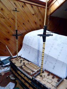
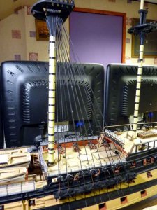
Here’s how the ship looks with its new mast:

PICT_V_4302
pict_v_4302.jpg
 
Last edited:
I’ve now completed the mizzen mast and the major part of its topmast. There’s not much difference between it and the other two masts. There are no cheeks on this mast and the deadeyes in the mast top are smaller but there is one odd difference; the blocks for the lifts on the fore and main masts come off the bottom of the mast caps whereas they come off the top of the mizzen mast cap. I’m not sure why but I’ve done as I’m told!
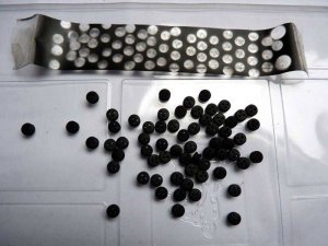
I mentioned earlier that I’d stuck the deadeyes on a post-it note to spray them. When I came to fit the smaller deadeyes on the mizzen mast I needed to spray some more. I decided I might as well spray all of them at once so this time I stuck them to a piece of sellotape (sticky side up but with the ends tucked under to hold it in place).
This worked well and as a bonus you get piece of modern art to go with them.

PICT_V_4401
pict_v_4401_.jpg

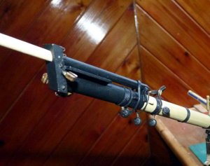
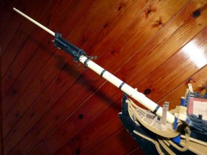
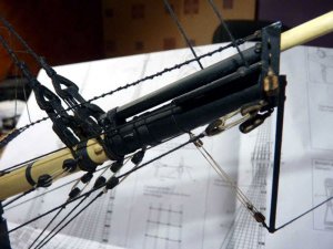
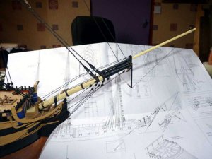
I’ve now made up the bowsprit as well. I know from past experience that this is the first thing that gets damaged whilst moving things around so I’m not going to fit the jib permanently at this time. The bowsprit looks strong enough to take care of itself providing I also leave off the dolphin striker.
I made a mistake in fitting the bowsprit cap. As with the mast caps, this should have a square hole where it fits on the jib and the cap supplied has a round hole. Because the cap fits at an angle, the hole requires a fair bit of work on it and I could probably have made it square, however mine’s round. I’m not going to worry about it as you can’t really see much of the joint and the dolphin striker will fit across it as well.

PICT_V_4402
pict_v_4402_.jpg

There are two more eyelets and blocks to fit on the bowsprit cap but these will pin the jib in place so, although I’ve drilled for them, I’ll fit them later.
At the moment the jib boom is held in place with a twist-tie!

This is what the complete assembly looks like:

PICT_V_4403
pict_v_4403_.jpg

It took me three goes to rig this correctly!
There are two hearts for the stays strapped around the bowsprit so I selected a couple from the parts box. These were decidedly on the clunky side so I trimmed them down before fitting them. After I’d fitted them, I realised these were the wrong ones – I’d fitted 10mm ones rather than 6mm ones.
So attempt No.2. This seemed successful so I moved on to next strop which only has a block under the jib. At that point I spotted that I hadn’t “Minded my Ps & Qs” or in this case my Ms and Ns. The ‘block’ under the bowsprit should be an ‘M’ which is a 5mm deadeye, not an ‘N’, a 5mm single block. Yes, I’d fitted 5mm blocks in the bottom of the strops for the hearts.
So, what you’re seeing is attempt No.3 with 6mm hearts and 5mm deadeyes!
At least the 10mm hearts look nicer for when I come to use them.

Here are a couple of pictures of how it looks now:

PICT_V_4404
pict_v_4404_.jpg

PICT_V_4405
pict_v_4405_.jpg

Time to break out the Lego and serve some shrouds.
 
Last edited:
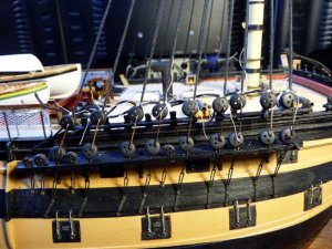
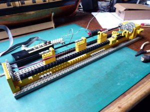
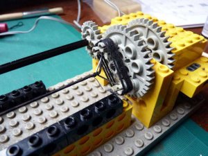
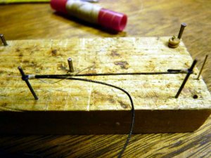
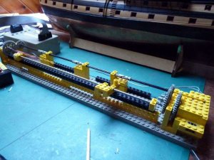
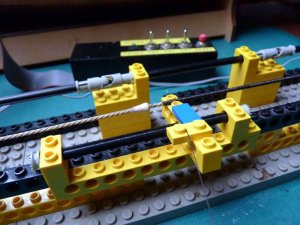
I had to look back through my previous build logs to find out how I’d made my serving machine. With a few updates, here’s the re-created contraption:

PICT_V_4501
pict_v_4501_.jpg

Note: There’s no mention of any serving in the instructions.

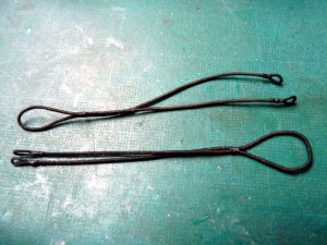
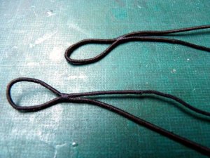
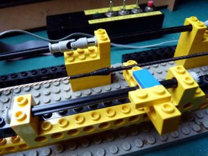
The first things I needed were two pairs of Burton pendants for the main mast. I made these up with an eye on each end and served them over the full length:

PICT_V_4502
pict_v_4502_.jpg

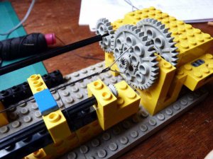
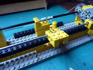
The arm with the blue piece on top is just a steady for the cord being seized, I can slide it along as the seizing progresses. It will do about 75-80mm at a time, then I have to move the assembly along for the next section.
(it's since been replaced with a much longer silver steel rod).

These are the two pairs of pendants ready to be fitted:

PICT_V_4503
pict_v_4503_.jpg

At this point, I got side tracked!
I’d pulled out the first of the rigging plans to get the sizes of the pendants, but when I was looking for the shroud sizes I had another look at the stays. The fore and main preventer stays are each smaller than their normal counterparts. On each mast the stay has a 10mm heart and the preventer stay a 6mm heart. The stay collars for the main mast have matching hearts, one of 10mm and one of 6mm. The size of the hears for the fore stay collars isn’t given on this sheet.
I suspect you can see where this is leading! I’d originally fitted two 10mm hearts on the bowsprit, realised I’d got it wrong and replaced them with 6mm ones as per the bowsprit diagram. It now seemed obvious that diagram was wrong and I should have had one of 10mm for the fore stay and one of 6mm for the fore preventer stay!
Having also managed to fit blocks instead of deadeyes, that made three attempts at that particular task, so I might as well go for fourth time lucky. 
This time, I opted to ignore the instructions and make up some double stropped open heart collars which I understand was the pre 1793 configuration.
Here’s what I came up with:

PICT_V_4504
pict_v_4504_.jpg

I thought I’d taken a picture with the strops bound to the hearts before I fitted them to the bowsprit, but apparently not. Here they are lashed in place:

PICT_V_4505
pict_v_4505_.jpg

The jib boom will pass through the hearts; at the moment it’s only temporarily positioned (and a little too far back).

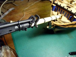
So, now for the shrouds. These are served where the pass around the mast head so I have to start serving near the middle. A few pegs in the gear wheel let me coil up the rest of the shroud:

These are the first two shrouds:

PICT_V_4506
pict_v_4506_.jpg

The foremost shroud is served over its full length. The instructions give the correct order for fitting the shrouds, i.e. starting with the forward starboard pair but the diagram shows the port pair going on first.

PICT_V_4507
pict_v_4507_.jpg

A rather untidy mess, but this is the full set of main shrouds:

PICT_V_4508
pict_v_4508_.jpg

I temporarily hooked up each shroud with pieces of wire to correspond to the drawing on the rigging sheet and made the wires 20mm long. The length is given in the instructions as 15mm. I still have the option of adjusting these as I’ve only made the throat seizings so far, but I think I’m going to leave them at their current length.
Here’s how they look.

PICT_V_4509
pict_v_4509_.jpg

Things are a bit more orderly at the top, but it sure is crowded up there!

PICT_V_4510
pict_v_4510_.jpg

And there are a couple of substantial sized stays to go round here. 
 
Last edited:
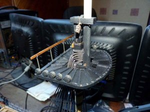
Next job was simply a repeat of that for the main mast, fitting the shrouds for the fore mast.
This time I made the temporary wire links between the deadeyes 15mm as per the instructions. They looked OK so I shortened the links I’d made for the main mast and re-positioned the deadeyes.
Here’s how they look on the foremast:

PICT_V_4601
pict_v_4601_.jpg

I won’t make the final seizings until all the stays are done and things have stretched and settled down. I can do the final adjustments at that time.

This is how they look at the top:

PICT_V_4602
pict_v_4602_.jpg

I’ve also done a little more work up front; I’ve lashed the bowsprit into position:

PICT_V_4603
pict_v_4603_.jpg

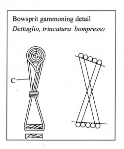
There are two diagrams of the gammoning and one could be confusing:

PICT_V_4604
pict_v_4604_.jpg

The right hand drawing is a view from the port side and correctly shows the line crossing front to back.
The left hand diagram is a fore and aft section and appears to show the line also crossing side to side. I could be persuaded to give it the benefit of the doubt and say that’s not the case, but it could mislead someone!

The final job was to make up the main stay collar. The plan shows this as the preventer stay but this is going to be the main stay.

PICT_V_4605
pict_v_4605_.jpg

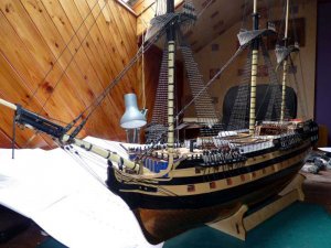
And finally here’s how it’s looking at the moment:

PICT_V_4606
pict_v_4606_.jpg
 
Last edited:
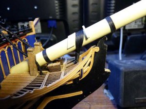
Well, that was this evening taken care of in reading your log from start to finish. I enjoyed your humour, tips and techniques and watching an excellent build come together, so thanks for a most entertaining evening. Regards.
 
Arthur

Thanks for sharing your build. I have not read all of it yet but it is very informative.

I do like to see that you have other hobbies like playing with Lego.

Cheers
Geoff
 
Thanks guys.
What I've posted here so far is about 50% of the existing log, and I've a couple of installments to add to the end to bring it up to date.
 
I’ve now fitted the shrouds to the mizzen mast as well. For a short time, it had a couple more shrouds than it should have!
There are two channels on each side for the mizzen mast and the forward of the two has seven deadeyes on it, so I fitted three pairs and one single shroud on each side. The bad news is that the mizzen mast only has six shrouds per side, the seventh deadeye is for something else, presumably a back stay.
The good news is that the main top mast has an odd number of shrouds of the same section, so I can use them there.
It doesn’t look any different to the fore and main mast so I’m not posting any pictures.

Next job was to make a start on the stays.
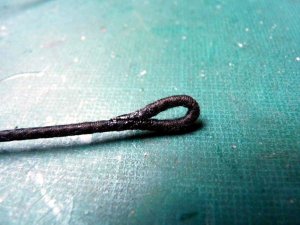
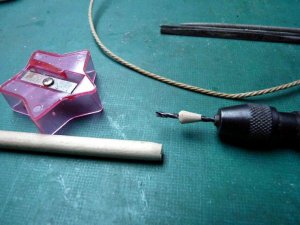
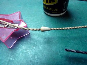
The main stay is a substantial piece of cord, it’s 2mm in diameter. I tried a new way of making the mouse. I drilled a 2mm hole in the end of a piece of dowel and then used a pencil sharpener to taper the end. I cut off the tapered section by rolling the dowel under the knife blade, but before I cut completely through it, I shaped the end.
Here’s the result:

PICT_V_4701
pict_v_4701.jpg

It’s probably a finer taper than it should be but that can be varied by varying the angle of the dowel in the pencil sharpener. The shallow angle made it much easier to serve later.
Here’s how it looks glued to the stay:

PICT_V_4702
pict_v_4702.jpg

Next job was to serve the upper section of the stay. With care, it was possible to serve up the end of the mouse. I made sure there was plenty of glue (PVA) on this part and left it to set before I served the rest of the mouse.

PICT_V_4703
pict_v_4703.jpg
Even with relatively shallow taper, the turns wanted to slide down to the left, but with a bit of care I could keep the turns together.
This is the completed serving:

PICT_V_4704
pict_v_4704.jpg

Next job was to make an eye on the end of the stay. I used the same technique as I’d used on the main stay collar, but as I didn’t explain it then, this is how I made it.
I applied some superglue to the end of the stay and when it had set I cut the end at a shallow angle. I next bent it back and again using superglue, I glued it to form the eye:

PICT_V_4705
pict_v_4705.jpg

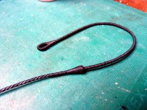
The final job was t seize over the glued joint. After being suitably tarred (liquid black shoe polish), here’s the upper section of the main stay:

PICT_V_4706
pict_v_4706.jpg

And here’s how it fitted:

PICT_V_4707
pict_v_4707.jpg

From this point, things were pretty straight forward; just a case of seizing a heart it to the bottom of the stay and lashing it to the collar:

PICT_V_4708
pict_v_4708.jpg

Moving swiftly along, do it all over again and this is the fore stay made off to the bowsprit:

PICT_V_4709
pict_v_4709.jpg

This is the present state of play:

PICT_V_4710
pict_v_4710.jpg

Note: If anyone is going to copy me and make off the main preventer stay to a collar on the foremast, I’d recommend making that collar before stepping the fore mast. I’m going to have to make the final three seizings on that collar with it fitted around the mast!
 
Last edited:
I made up three new hearts for the preventer stays. They’re smaller than the ones supplied for the stays, but a fair bit larger than those supplied for the preventer stays.
The first part of making up the main preventer stay collar was relatively easy but fitting it around the mast was, as expected, a bit of a fiddly job.
The chock fitted to the mast is to hold the collar, it’s not going anywhere, it’s got two brass pins through it!

PICT_V_4801
pict_v_4801.jpg

The dirty mark on the mast is from the main stay; it cleaned off easily later on.

The first seizing's done; two more to go (and the mast’s clean again by this time!)

PICT_V_4802
pict_v_4802.jpg

And this is the completed collar.

PICT_V_4803
pict_v_4803_.jpg

The preventer stay is supposed to be approximately 2 feet above the main stay. That’s 8mm at this scale and it looks about right:

PICT_V_4804
pict_v_4804.jpg

The mizzen stay is also made off to the mast ahead of it, i.e. the main mast, but I’d already fitted a deadeye to the mast as per the instructions. The only thing that’s stopping that collar sliding up the mast is the ‘iron band’ round the mast – a strip of black card! Still, it seems to be doing the job:

PICT_V_4805
pict_v_4805.jpg

Here’s a picture of the fore stay collars, Honest, the preventer stay heart is smaller than the one behind it!

PICT_V_4806
pict_v_4806.jpg

I’ve started making off the deadeyes on the shrouds properly. They look a lot tidier than they did in the pictures I posted previously, but they still have the wire links in them.

PICT_V_4807
pict_v_4807.jpg

One set down, five more to go. That’s going to keep me busy for a short while.
 
Last edited:
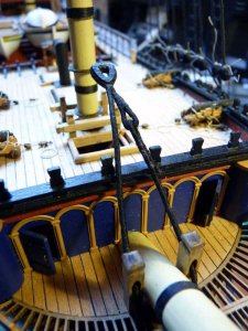
All the deadeyes are now made off properly. I had to adjust the positions of two or three slightly where the shroud had either stretched a bit or settled into position, but most were OK.
Once that was done I laced up all the deadeyes. The ends of the lanyards are still to make off at a later date – just in case any final adjustments are needed!

PICT_V_4901
pict_v_4901.jpg

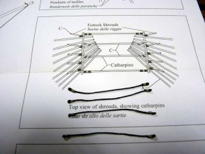
I considered doing some more work on the stays next but instead decided to do the catharpins. The futtock staves are made from 1mm brass wire so first job was to decide where they were positioned.
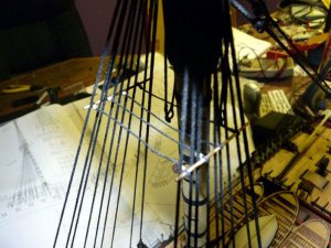
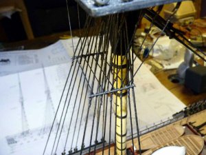
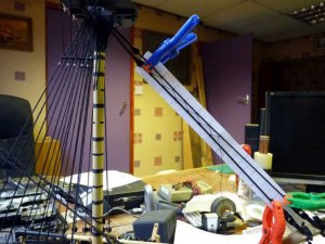
The diagram shows them just below the level of the top wolding on the main mast so I clamped two pieces of wire to the shrouds at the appropriate positions.

PICT_V_4902
pict_v_4902.jpg

I measured the distance between the two and it was almost exactly 50mm, A nice round number to work with! The actual spacing isn’t particularly critical as any discrepancies will only move the staves up or down the mast slightly, but the catharpins do need to be all the same length. This is how I made them up:

PICT_V_4903
pict_v_4903.jpg

There are several different styles of catharpins but the ones for this period were simply straight, ending in eye-splices. These are supposed to be lashed to the shrouds but I opted to pass the futtock stave through them instead. This is the method shown on the diagram for both the catharpins and the futtock shrouds but I only fitted the catharpins this way.
The diagram also shows the futtock stave inside the shrouds whereas it should be on the outside of them.

PICT_V_4904
pict_v_4904.jpg

Next job was a trial fit to see where to position the catharpins. One at each end of the stave, as shown in the diagram, is definitely not an option unless you want to drill a hole in the mast to thread it through!
This is where I opted to position them:

PICT_V_4905
pict_v_4905.jpg

I should have blackened the brass wire before trial fitting them; there then wouldn’t have been any need to remove them for blackening at this point.
I next lashed the stave to the shrouds and adjusted the height such that the shrouds weren’t pulled out of line when the catharpins were pulled taut.
The futtock stays are supposed to take one turn around the stave and are then seized to the shrouds immediately below it. I opted to cheat slightly by omitting the turn around the stave. This made things a little less crowded and it was much easier to adjust the tension in the futtock stays.
This is the completed arrangement:

PICT_V_4906
pict_v_4906.jpg

Seizing the futtock shrouds to the shrouds was much easier than I expected, probably because everything was firmly held in position by that time.
 
Last edited:
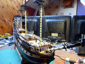
I’ve now completed the catharpins on the fore and mizzen masts. The only difference from the pictures I posted earlier is that I only fitted three on the mizzen mast whereas the other masts have four.

So, back to the stays.
The main and fore stays each have snaking to their respective preventer stay. This is supposed to be done using 0.1mm natural thread which should be stained black on completion. Instead, I opted to use black cotton thread. The plan showing the snaking (sheet 8) is at half scale so I measured the spacing and doubled it. It worked out at about 7.7mm. I’m reasonably good at mental arithmetic, but don’t see any need to make life difficult so I opted for 8mm! I started on the main stay, but forgot to take a photograph so here’s a picture of how I did it on the fore stay:

PICT_V_5001
pict_v_5001.jpg

It seemed logical to use a clove hitch to tie the snaking to the stays but that made the thread twist sideways at each knot. Crossing the threads over above/below the knot made things better, but I wasn’t particularly enthusiastic with the results. It looked more like a set of those curly brackets – { & } – than a nice saw tooth pattern.

PICT_V_5002
pict_v_5002.jpg

When I started, I made a guess at how much thread I needed and decided it would be 1 ½ times the length of stay plus some extra for the knots.
I ran out of thread about ¾ of the way down!
It wasn’t difficult to end the first piece and start a new piece by tying a simple half-hitch on each end. That actually looked slightly better than the clove hitches I’d been using so I experimented with different knots before I did the snaking on the fore stay. The next picture shows the method I used; I’ve done a little bit of editing with Photoshop in an attempt to show which bit goes over or under which.

PICT_V_5003
pict_v_5003.jpg

This is how the fore stay turned out:

PICT_V_5004
pict_v_5004.jpg

I was much happier with how this looked so I took a pair of scissors to the snaking on the main mast and replaced it.

Next job was to fit the crow’s feet to the tops. The instructions show this as 0.1mm line, but also show the tackles holding the euphroe blocks to the stays as 0.1mm. That seemed a bit of a mismatch to me so I opted to use 0.25mm line, together with 3mm rather than 2mm blocks.
This is how it looks:

PICT_V_5005
pict_v_5005.jpg

Finally, this shows the revised snaking on the main stay after making off the crow’s feet:

PICT_V_5006
pict_v_5005.jpg

There are two tackles shown hanging from these stays. I assume these are for manoeuvring the ship’s boats, so I’ll leave them off for the time being.
 

Attachments

  • pict_v_5006.jpg
    pict_v_5006.jpg
    52.9 KB · Views: 150
Last edited:
I’m going to start this entry with a picture of a nail: :D

PICT_V_5101
pict_v_5101.jpg

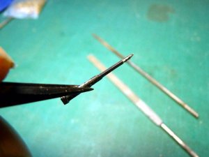
As you can see, it’s been somewhat modified. It’s actually an oval nail, quite by chance because it just happened to be lying about, but it did turn out to be a significant benefit. The shank has been filed down to 1mm square and a few notches have been filed in the end. The benefit from the fact that it was an oval nail was that it didn’t twist whilst I was holding it.
The reason I needed this was because I was making the final three mast sections and the fids for these are 1mm square.
Here’s proof that, after using it, you can fit a square peg in a round hole:

PICT_V_5102
pict_v_5102.jpg

(Well it was round when I started!)

The drawings for these sections of mast show them to be made from 4mm dowel, but they are 4mm square at the bottom and, like the topmasts, are supposed to be built up to this size by gluing 4 x 1mm strips around the base of each mast.
This time I simply started with 6mm dowel. Less messing about, but I did have a much bigger pile of shavings when I’d finished.

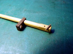
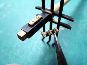
The fore and main topmasts have sheaves fitted on each side of the mast head. The cross trees have to go on before these sheaves are fitted but I wanted the cross trees free so I could match them with the upper topmast/royal mast. Having done that, I now needed to fit the sheaves.
These are simply short strips of planking with three cross pieces glued to them and brass pins through them for the sheaves. Whilst I was at it, I thought I might as well add a touch of luxury, so I chopped some short lengths off the end of some black plastic cable sheathing and dropped them over the brass pins:
I’d pre drilled the holes in the mast top to match the holes in the wood strips so it was just a case of scraping away the paint where the sheaves would fit, applying some glue and pushing the pins home.
And then immediately carefully levering the pins back out again, cleaning off the glue, and fitting the cross trees!

PICT_V_5103
pict_v_5103.jpg

Once things had set, I cleaned up the wood strip, chamfered the corners and painted them black.

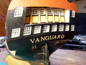
I read a post recently, but can’t now find it, about fitting the lettering on the stern and the problems of spacing and positioning the individual letters. I’ve not fitted any decoration on the stern yet, but fitting that looked as though it could best be done with the ship stood on its nose again. That would be quite a challenge once I fitted the upper masts so I decided to do that whilst those sections were still removable.
I painted the letters yellow ochre while they were still attached to the photo etched sheet. They looked to be nicely spaced on the sheet and were obviously correctly aligned so I figured I could maybe tape them together before I cut them from the sheet. The obvious problem is that the area they fit on to is slightly curved whereas they are in line on the sheet, but the curve is relatively gentle.
I stuck a length of Tamiya masking tape across the base of the letters leaving it longer than the name at each end and cut the letters from the sheet. It was easy to position the name on the stern with the middle letters in the correct place but I wasn’t too sure how things would progress. However, it was possible to press down the tape between the letters to hold things in place so I pressed the tape down on the left hand side and folded the letters back between the ‘G’ and the ‘U’. I applied some superglue to the back of the ‘G’ and folded the letters back into they’re correct position. Once the glue had set, I found it was relatively easy to repeat the procedure with the letter ‘A’ and just twist the tape slightly to follow the curve. All went well until I got to the last letter which fell off the tape, leaving its paint behind! However the paint showed where it should go so I was able to glue it in the correct position.
Once all the letters were glued in place, I was able to remove the tape, which neatly removed the paint from every letter! Not exactly a disaster, but definitely a nuisance; fortunately it was easy to repaint them.
Here’s how it looks:

PICT_V_5104
pict_v_5104.jpg

I’ve fitted the blocks on the mizzen mast so far but still have a few to fit on the other two masts. In the meantime, this is how it looks at full height:

PICT_V_5105
pict_v_5105.jpg

Well nearly full height; I think I’ve clipped a little bit off the top!
 
Last edited:
After a bit of a lull in the construction, it’s time for an update. There’s not been a lot of progress but I’ve now fitted the topmast shrouds and the lower backstays.
As with the lower shrouds, I’ve served the centre section of each pair of topmast shrouds but that may have been a mistake. There’s not a lot of room on the mast head and the stack of shrouds reached up to the sheaves. Anyway, before I get into that, I’ll describe a mod I made to my serving machine.

One of the problems when serving a line is that of holding the line in place whilst serving it. All’s well near the end but as serving proceeds, the line is pulled to the side making it difficult to keep an even tension. I more or less solved this by providing a ‘steady’ for the line to rest against. This was simply a short Lego beam which I could slide along as serving progressed. The problem was that it slid along a Lego axle and the longest ones I have are only around 100mm long. That meant I could only serve a relatively short length then I had to stop, Remove the rod and its supports and refit it further along.
I decided to see if I could make something longer, possibly using a length of welding rod so I went on a recce mission to the garage.
That turned out to be much more successful than anticipated and I found a very nice piece of silver steel in my stock. Although it was marginally smaller diameter than the Lego shaft, a couple of turns of Tamiya tape were all that was required to fit it in place.

PICT_V_5201
pict_v_5201.jpg

As you can see, the shaft now runs all the way along and I can serve the full length of a shroud in one go.
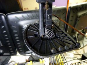
The other advantage is that I can use two beams, spaced apart, to slide along the rod. That means that it doesn’t tend to jam when pushed sideways so if the thread is fed in at a slight angle it feeds itself along automatically.

Note: There is now a still later version of the serving machine with full building instructions and parts list described here.

PICT_V_5202
pict_v_5202.jpg

So, back to the shrouds. As with the lower shrouds, I’d laced up the deadeyes but not finally made them off. Time to see how things lined up:

PICT_V_5203
pict_v_5203.jpg

Not too badly, but not perfectly, the mizzen mast seemed to be the guilty party. I don’t think it would matter that much but it’s one of those things that would annoy me if I didn’t get it right.
To my surprise, adjusting the tension of the lower shrouds wasn’t the way to go; although it had some effect, any significant change in the tension distorted the shrouds above the futtock stave.
At this stage I’d fitted the back stays. As I mentioned earlier, there’s not a lot of room on the topmast mast heads and I opted not to serve these. I also fitted them round the shrouds rather than round the mast head above the shrouds on the fore and main masts. The mizzen mast doesn’t have sheaves so that wasn’t a problem.

PICT_V_5204
pict_v_5204.jpg

Adjusting the tension of the back stays, particularly the topmast ones was more effective. This was the result:

PICT_V_5205
pict_v_5205.jpg

Although there are still some more backstays to fit, I think I need to fit some of the fore stays first. As a start I decided to do a little experimenting up front.
I did a little bit of carving on a small piece of dowel to make a couple of sheaves. With a little bit of filing I was able to slot these into the holes in the bees. The bees are made from 1.5mm plywood which was just thick enough to let me drill a 0.7mm hole from the side for an axle:

PICT_V_5206
pict_v_5206.jpg

At the moment I’m not sure whether I need to make two more for the other holes.

This is an overall picture of how it looks at the moment:

PICT_V_5207
pict_v_5207.jpg
 
Last edited:
Continuing work on the standing rigging, I’ve now fitted the topmast stays. Although the plans clearly show the tackles for these, they do not show the belaying points.
Each rigging sheet has a plan view of the deck at the top. There are various belaying points shown on all these sheets except this one, sheet 8. I am beginning to wonder if this is an omission.
After a little research and helpful guidance, I’ve belayed them to timberheads on the fore rail.

PICT_V_5301
pict_v_5301.jpg

PICT_V_5302
pict_v_5302.jpg

Whilst working in this area, I also fitted the bobstays and some of the bowsprit shrouds:

PICT_V_5303
pict_v_5303.jpg

The main topmast stays run, via blocks on the foremast, to tackles at the base of that mast. I’d fitted these blocks to the foremast earlier, as per the instructions. However, although I’d identified these as being for the stays, I hadn’t looked in detail at what that implied! The topmast stay is a substantial piece of rigging and is represented by a length of 1.3mm cord. That wasn’t going to go through the existing hole in the block!
The block is attached just below the hounds which puts it between the futtock shrouds and above the catharpins. Getting in there to drill out the hole was an interesting challenge!
Again, although the tackles for these are shown, the belaying points are not. These should run to the fore bitts so I opted to drill these and fit belaying pins:

PICT_V_5304
pict_v_5304.jpg

If required, I just have enough room to drill for three more pins if necessary.

The mizzen topmast stay has also been fitted, but that is simply made off with a pair of deadeyes.
 
Last edited:
I finally convinced myself to tie some ratlines!
I started with the main shrouds and opted for 15 inch spacing and natural colour. (The instructions say black). 1:72 scale is near enough 4mm to 1 foot so that’s 5mm spacing.
I printed off a page from Excel with top and bottom borders and various row heights. A little bit of measuring and calculation said that 14.15 was the height to use.
Slicing the sheet in two gave me templates for the port side main and fore ratlines:
PICT_V_5401
pict_v_5401.jpg

Some (fairly long) time later, this is how it looked:

PICT_V_5402
pict_v_5402.jpg

I’ve previously tried tying the ends with clove hitches but they don’t look right and I also found they tended to slacken too easily. They were OK once they were glued but I don’t want to do that one at a time whilst I’m working. I’ve also tried various other knots and previously settled on simply tying a clove hitch followed by a half hitch. That made things look a bit better as the cut end didn’t stick out at the sides and the knot stayed tight.
This time I passed a single turn round the outer shroud and tied two half hitches with the cut end pointing inboard. That’s worked quite well, the ratline stays square to the shroud and the knot looks a little more like an eye splice and lashing.
Here’s how the main shrouds look now:

PICT_V_5403
pict_v_5403.jpg

I haven’t forgotten the futtock shrouds, I’ll cut up my templates to do those later.

Here’s another picture of progress so far:

PICT_V_5404
pict_v_5404.jpg

I need to find another task for a bit of variety before I start on the foremast shrouds. Maybe some more rigging on the bowsprit!
 
Last edited:
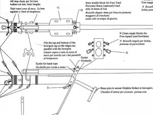
Ok, back to the bowsprit and I’m already confused!
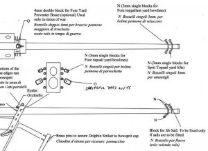
I made up the bowsprit cap as per the following diagram. It shows a number of eyelets in the cap, four of which run down the side. The top ones on the sides are identified but not the other three.

PICT_V_5501
pict_v_5501.jpg

The following drawing is on the plan I’ve recently been working from showing the shrouds and stays. On this and all the rest of the diagrams there are only three eyelets shown.

PICT_V_5502
pict_v_5502.jpg

I’d already fitted the bowsprit shrouds shown in this diagram and was expecting to fit another pair running to the bowsprit cap so I thought the bottom eyelets were for these shrouds. There is a second eyelet shown in the side of the hull where these shrouds would be expected to run from but looking through the plans, there is no mention of any additional shrouds.
I decided these had simply been missed in the diagrams and opted to fit them using the eyelets shown in the hull and the lower eyelets in the bowsprit cap. Petersson’s book shows all the shrouds made off using hearts whereas all the other shrouds on Vanguard’s bowsprit use deadeyes. As these shrouds are the only ones made off to eyelets, I opted to use hearts. I had four small ones that were supplied for the stays that I hadn’t used; they were rather too thick but some serious sanding solved that problem.

A little bit of searching ahead identified the functions of the other eyelets and let me add a few more items to my rigging table. They’re for the spritsail yard slings and lifts.

PICT_V_5503
pict_v_5503.jpg

Now do you remember that I moved on to the bowsprit rigging as a change from knotting ratlines? Well the bowsprit has two 'manropes' with knots every 3mm!
They’re apparently supposed to be figure-of-eight knots but they’re a bit too large and hard to get in the right position so simple over-hand knots will have to do.
The problem was how to get them correctly spaced. After looking to see what was readily available, I found the almost perfect solution:

PICT_V_5504
pict_v_5504.jpg

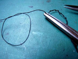
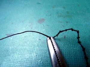
The tip of the jaw is just 3mm wide so the knots are at just slightly over 3mm spacing but almost is good enough in this case, it’s just a case of pushing each knot close up against the hemostat jaws as it’s tightened:

PICT_V_5505
pict_v_5505.jpg

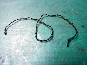
Some considerable time later, this was the result:

PICT_V_5506
pict_v_5506.jpg

Important note: Tying a knot too many is a serious mistake; it has to be undone to seize the hook in the right place. (Don’t ask me how I know!)
This is how the bowsprit looked with the shrouds and manropes fitted:

PICT_V_5507
pict_v_5507.jpg

There are two legs from the stays holding up the middle of these ropes. According to Lees, these were no longer fitted in this period but they’re shown on the plans and without them the ropes foul the stay collars, so they look better with them fitted.
You can also see in this picture that I’ve finally fitted the jib boom. I’ve left it off as long as possible to avoid breaking it so I’ll just have to be careful from now on.

The dolphin striker is made of 1.5mm plywood and comes from the same sheet as the stern gallery windows. That’s the sheet that more or less fell apart along the bottom edge due to what appeared to be a lack of glue between the plywood laminations. I thought that the rest of the sheet was OK and the dolphin striker looked fine when I removed it from the sheet. However the bottom section literally peeled apart whist I was fitting it. It wasn’t much of a problem though, I just glued two strips of 1mm walnut planking together and sanded them to size.
I was expecting some gammoning to hold the jib boom in position but there’s no mention of it anywhere on the plans so, back to the books. They confirmed that’s the way it’s done but apparently it’s not called gammoning. In this case it’s a crupper.
This picture also shows the hearts on the bowsprit shroud and the tackle on the martingale.

PICT_V_5508
pict_v_5508.jpg

Once again, the plans have me confused.
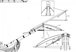
There are several blocks at the end of the jib boom. The plan view shows four blocks and identifies these. However the elevation drawing shows three more blocks, only one of which is identified. Looking back at picture 5502, the top block should be for the fore topgallant stay but I’ve no idea what the bottom block is for!

PICT_V_5509
pict_v_5509.jpg

I’ve made off the block for the stay with the martingale but I’ll fit the other blocks later.

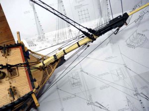
This is an overall view of the bowsprit at this stage:

PICT_V_5510
pict_v_5510.jpg

Looking at the tackle on the martingale, it looks too long. I’m going to remake the martingale and lengthen it so that the tackle is a similar length to the hearts and deadeyes.
 
Last edited:
I seem to have been tying ratlines for an awfully long time now, probably because I keep finding excuses to do something else!
Having completed all the ratlines on the lower shrouds, I thought I could have a change before moving up to those on the topmast shrouds.

PICT_V_5601
pict_v_5601.jpg

I was considering fitting the rest of the stays so I first needed to fit the topgallant shrouds. However, when I looked at these I realised that they run all the way down behind the topmast shrouds to the mast tops. Fitting those before tying the next set of ratlines was a recipe for disaster; I’d be guaranteed to end up tying some of the ratlines round both shrouds at the same time.
I made up the fore topgallant shrouds and coiled them up on the cross trees for the moment. Back to tying ratlines. (Did I mention I get bored tying ratlines?)
Having completed the ratlines on the fore mast, I could then make off the upper shrouds. I’d measured these to reach the main top but when I came to tie them off I found they weren’t really long enough. I’d obviously cut things fine and once they were looped round the futtock stave there wasn’t really enough spare length to work with.
Simple solution though, I moved them to the mizzen mast and made new ones for the fore mast.

PICT_V_5602
pict_v_5602.jpg

This is how things stand at the moment:

PICT_V_5603
pict_v_5603.jpg

Oh well, back to tying ratlines.
 
Last edited:
Back
Top