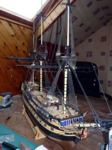
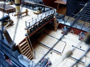
HMS Vanguard 1787 - Victory Models - 1:72 [COMPLETED BUILD]

Time for a long overdue update.

I’ve now almost – possibly - finished the standing rigging.
The ‘almost’ is because I know of a couple of jobs still to do, neither of which should take very long.
The first is to lace up the deadeyes on the topmast backstays properly. At the moment they’ve just got wire links in them.
The second is similar, to fit the topgallant back stays.
The ‘possibly’ is a bit more of a puzzle and is whether or not I should fit any royal stays. At first I thought these had simply been omitted from the plans but now I’m not so sure. Checking through the plans I find that not only are there no royal stays, there are no royal yards or sails either.
I’ve sent Chris Watton a PM to see if he can clarify things.

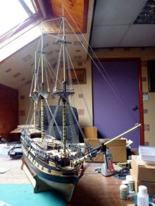
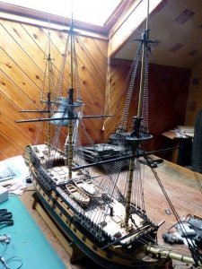
Anyway, here’s how it looks at the moment:

PICT_V_5701
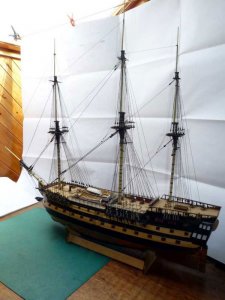
pict_v_5301.jpg

It’s got a bit on the large side, that’s the largest sheet of paper I’ve got acting as the background!

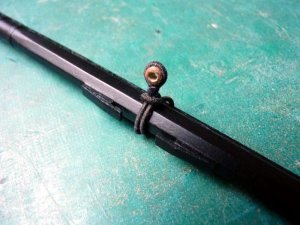
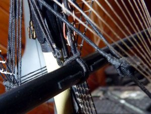
The topgallant shrouds are shown as being simply tied off under the topmast deadeyes. I opted to insert ‘thimbles’ and lashings at that point. They’re not easy to make out in the following picture but you can just make out the arrangement:

PICT_V_5702
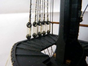
pict_v_5302.jpg

Now we come to the fore stays for the topgallants and some minor guessing games are called for.

The mizzen topgallant stay is shown heading down to the fore top where it is presumably made off to one of the eyelets there. I don’t know what all these are for and opted to use the first from centre on the starboard side. Again, I inserted ‘thimbles’ and a lashing:

PICT_V_5703
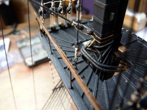
pict_v_5303.jpg

The main topgallant stay is made of to the collar of the block for the topmast stay as per the instructions:

PICT_V_5704
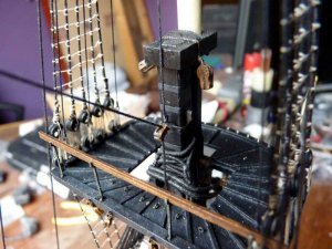
pict_v_5304.jpg

Finally, the fore topgallant stay is made off via a tackle to the starboard bow timberhead. The running end of this tackle (line number 3 on the plan) heads sternwards, never to be seen again. I’ve assumed it runs to the fore beakhead bulkhead timberheads, but which one is the question. The plans show lots of lines will be made off here later.
This is how it’s made off:

PICT_V_5705
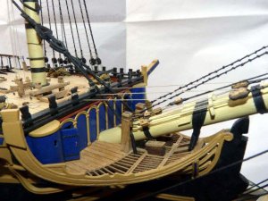
pict_v_5305.jpg
 
Last edited:
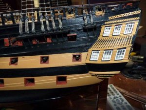
Work on Vanguard has, at the moment, come to a stop. Originally due to holidays, but now whilst replacing the house windows. However, just before going on holiday, I had a break from rigging and did some work on the stern decoration.
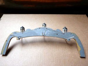
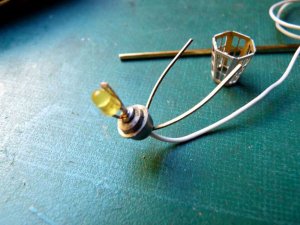
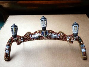
There are three lanterns at the stern which fit into the large resin casting that runs across the top of the stern. As you may remember from the earlier log entries, I’m fitting lights in Vanguard, so I need these lanterns to work. Although I’d run the wires through to the stern, I hadn’t quite decided how to connect them. Using the photo etched bracket as one connection and the bottom (1mm brass wire) bracket as the other seemed obvious but the ends of the top brackets would come out on the poop deck.
When I tried the casting in place, I realised that there was a narrow strip that was below the poop deck but above the bottom of the casting. As long as I could get my connections to that level, I could hide my connections under the stern balcony roof.
Here’s where the wires come to:

PICT_V_5801
pict_v_5808.jpgpict_v_5801.jpg

For some reason, I decided the top of section should be painted red. In fact, only the bottom centre of that area needed painting, and it should actually be black!

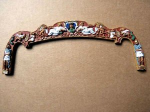
With the wiring sorted out, the next job was to paint the casting. Not one of my strong points, but at least there are a few examples out there for reference. In the event, it didn’t turn out too badly:

PICT_V_5802
pict_v_5802.jpg

My intention was to solder the photo etched bracket to the lamp base as one connection and drill the centre hole slightly larger so that I could insulate the 1mm brass wire where it passes through the base, but at this point plan A came to an abrupt halt. Whatever the lamp base is cast from didn’t want to be soldered, even using aluminium flux and solder!
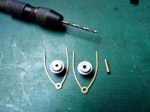
This is the kit of parts for plan B:

The lamp base on the right has been drilled out to 2mm diameter, as has the hole in the bracket. The additional item is a short length of 2mm tubing (1mm bore) to fit through the casting:

PICT_V_5803
pict_v_5803.jpg

With the tubing fitted in the base, I could now solder the bracket and the LED to the tubing. Note: In order to solder so close to the LED, I held the LED lead in the tip of a pair of long nosed pliers as a heat sink.
The length of wire is for the bottom bracket of the LED. It’s stiffer than the normal, more common sizes of single core wire and is 1mm overall diameter.
Unfortunately the only colour I have is white so I’ll have to paint it black later.
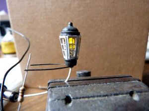
The lantern body required a little care in bending, but a spot of solder on the inside to hold the ends in place made it much easier to adjust the final shape.

PICT_V_5804
pict_v_5804.jpg

The white wire was then simply pushed through the tube and soldered to the LED (Again using pliers as a heat sink).

PICT_V_5805
pict_v_5805.jpg

Not a lot of room to spare, but it does fit:

PICT_V_5806
pict_v_5806.jpg

I cut some thin celluloid to fit inside the lantern, but decided it wasn’t really necessary so I left it out.
When I came to blacken the top bracket, I found the top and bottom castings blackened even easier than the brass pieces.
Here’s the completed lantern in operation:

PICT_V_5807
pict_v_5807.jpg

Next job was to carry out some carving on the back of the resin casting.
I carved grooves between each of the top brackets and down to where the centre slot will be. I then araldited wires in each groove which will be soldered to each lantern. I also carved grooves from each bottom wire/bracket. The insulation will be stripped from those wires and they too will be araldited into the grooves.

PICT_V_5808
pict_v_5808.jpg

This is how it looks from the proper side:

PICT_V_5809
pict_v_5809.jpg

The wires still need to be painted black. (To get the paint to stick, I suspect I might have to spray them.)
 
Last edited:
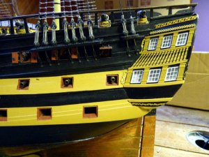
Although work on Vanguard has slowed to a crawl over the last month or so, it’s not entirely stopped.
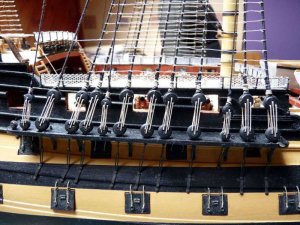
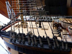
I’ve worked my way around the channels and laced up all the deadeyes properly for the shrouds and back stays:

PICT_V_5901
pict_v_5901_.jpg

I could have posted a separate picture for each channel, but apart from the number of shrouds and the fact that the deadeyes on the mizzen mast shrouds are a couple of millimetres smaller, they all look more or less the same.
No prizes for recognising this as the starboard main channel!
 
Last edited:
Whilst I was figuring out what to do with my shifting backstays, I decided to tidy up some decorative work at the bow.

The first item was the colour of the main bow rail (part 123). The instructions say ‘paint yellow/ochre before fixing in place’ – which I did. This piece is extended at the top to form a timberhead and I noticed that other people had painted this part black. What I couldn’t make out was how far this black area went. Although the bow rails seemed to be yellow, there seemed to be some part of them that was black.
Enlarging the picture on the box lid showed that, on that model, the top portion of the rail was black and the rest yellow. With the rails now glued in place, that was going to be a challenge!

The next item was a bit of decoration on the stem between the cheek rails which I’d overlooked. There are three different versions for the different ships. For Bellerophon and Elephant, there are instructions for painting them, For Vanguard, you’re on your own! However, as gold was the common theme for the other two, it wasn’t a difficult choice.
The etching is either a dragon or a sea serpent and I expected it to be facing forwards (and I think it looks better that way) but after checking the plans and then double checking with the part numbers, I convinced myself they face backwards.

The remaining job was to fit the figure head. He’s been temporarily disarmed. He should have a sword in his right hand but there was a bubble in the casting where it fits so I’ll have to use a drop of epoxy to hold it. If I fit it now I’m sure to knock it off sooner or later.
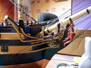
Here’s how the bow looks now:

PICT_V_6001
pict_v_6001_.jpg

As you can see, I reached a bit of a compromise with the main bow rail; I painted both the top and bottom of the rail black leaving the two panels yellow.
 
Last edited:
Progress on Vanguard has been on hold or on a go-slow for the last month or so. In part, that was due to holidays but mostly it was my son’s fault. He showed me a video of a Useless Box and said he was thinking of making one.
So far he hasn’t started his – but I’ve finished mine!

If you’re wondering what a useless box is, there are lots of videos on YouTube.
If you’re the sort of person who’s attracted to weird gadgets, be warned, you too could end up being side-tracked!

Anyway, back to Vanguard. I’ve now completed the standing rigging.

PICT_V_6101
pict_v_6101_.jpg

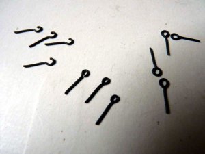
The first of the outstanding jobs was to fit the shifting backstays to the main and fore masts. All didn’t go quite so smoothly as it should have though. The first hiccup was only minor though. I needed a couple of hooks for each stay so I cut eight of them from the photo etched sheet and applied the blackening fluid to them whilst I made up some stays. I took the hooks out of the evil brew and put four of them on the fore deck and four on the poop deck so I wouldn’t lose them.
I think these stays would have been better made up earlier as I think they should be under the fore stays, so I lifted off the mast cap and the blocks that are strapped round the mast head. I was then able to pass the back stays through the fore stay collars and sit them under the fore stays.
I also think these stays on the fore mast are actually breast stays rather than shifting backstays, but it doesn’t actually make any difference and I made up the tackles as per the diagram. The tackles run from an eyelet near the front of the channel to a block hooked to another eyelet between the foremost two deadeyes. So I needed to attach one of my hooks to a 3mm block.
I carefully picked up one of my hooks with a pair of tweezers from the fore deck. Unfortunately, I then knocked my tweezers against the forestay collar and dropped the hook – down the forward companionway! It’s still in there somewhere.
Anyway, this is how the fore mast breast stays look:

PICT_V_6102
pict_v_6102_.jpg

If you look at the stern end of the channel, you can just see the fore royal backstay. I made those off to eyelets at the aft end of the channels. The lashings should be between thimbles but thimbles at that size were a bit too much of a challenge so I used brass rings instead.
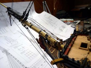
With the royal backstays in place, I was then able to fit the royal fore stay. I made it off on the port side of the bowsprit in the same way as the fore topgallant stay on the starboard side:

PICT_V_6103
pict_v_6103_.jpg

You can see it more clearly in this close up, it’s the one nearest the camera:

PICT_V_6104
pict_v_6104_.jpg

Next job, the shifting backstays on the main mast, was more or less a repeat of the breast stays on the foremast. However this is where the next problem appeared. It was a mistake made previously and nothing to do with the task in hand, but it came to light as I was about to fit the stays.
The main topmast stay passes round the mast head and passes down between the aft pair of cross trees; the main topmast preventer stay should do the same. Somehow I’d got things wrong, the preventer stay was correctly located on the starboard side but ran between the forward pair of cross trees rather than the aft pair on the port side.
How to rectify this had me scratching my head! I could slacken the stay off, but it now ran to a fiddle block which wouldn’t pass through the eye in the upper end of the stay so I couldn’t simply remove it and re-thread it. Neither could I simply loop the stay back over the end of the cross tree because the middle topgallant shroud was threaded through the end of it. I could probably replace that shroud, but it was part of a pair so I would actually have to replace the pair which run all the way down to the main top.
At this point, I was seriously considering breaking off the port half of the centre cross tree. The stay would then simply drop into the correct position and I could then glue the cross tree back in place. I’m pretty sure this would have worked but I had another idea. Decidedly risky, but it worked O.K.
I very carefully cut a slot in the end of the port centre cross tree so I could lift the shroud out of the end. If I’d accidentally cut the shroud I’d have been wishing I’d opted for the more brutal option instead!
With the shroud out of the way I could simply unhook the tackle from the shroud which allowed me to loop the upper end of the preventer stay over the end of the cross tree. That done, I hooked the shroud back in place. The notch in the end was virtually invisible but a spot of glue followed by a dab of black paint completely hid the evidence.

So, back to fitting the shifting backstays and yet another snag appeared. I’d fitted various eyelets in the channels before fitting the channels themselves, but there wasn’t one in the position shown on the rigging plan. Not a major disaster, I could drill the channel from underneath to fit an eyelet but I looked through the pictures and diagrams to see where I’d gone wrong.
The answer seemed to be that I hadn’t! The drawing, Rigging stage 3, on sheet 9 shows the tackle running from an eyelet at the aft end of the channel, through the block on the end of the stay to a 3mm block which, together with another 3mm block further forward on the channel, forms a tackle to tension the stay.
Looking at the picture on the box lid, the arrangement appeared to be the reverse of this, the tackle runs from an eyelet part way along the channel, through the block on the end of the stay and the pair of blocks which tension the stay are at the aft end of the channel. This arrangement matches up with the eyelet locations in the channel so I opted to rig things that way.
Since then I noticed that the central picture on the cover of the instruction book very clearly also shows this arrangement rather than the one on sheet 9:

PICT_V_6105
pict_v_6105_.jpg

With that resolved, I fitted the royal backstays in the same manner as those on the foremast. The main royal stay is similar to the main topgallant stay, running to a block on the foremast and then, via a lashing, to the collar of the fore topgallant preventer stay.
Note: I eventually opted fit royal stays on the main and fore masts, but not the mizzen mast.

With all those stays in place, things are looking bit more involved up top:

PICT_V_6106
pict_v_6106_.jpg

Here’s a more artistic view of the same section of mast:

PICT_V_6107
pict_v_6107_.jpg
 
Last edited:
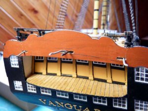
I decided to have a change at this stage and fit some of the decoration to the stern galleries.
I started by gluing the decorative columns between the lower stern windows. That was actually a mistake, but I only realised it a few minutes ago. With the columns in place, there is a decorative strip that runs the full width of the stern below the windows and columns. The strips are white metal castings and there are 26 of them supplied. I’ve already used some on the bow rails and decoration and, together with those I’ve now used, that only accounts for 8. I need a few more to complete the stern, but not 18! Either I’m missing something or Victory Models have been very generous. The drawing shows a strip fitted below the stern balcony (full width, but in three discrete sections). It also shows one on top of the balcony railings but I have my doubts about that arrangement and I don’t think I’ll be fitting that one, so even less of them required.
Unfortunately, the strips aren’t long enough to run the full width of the stern so I was faced with having a joint in the middle. The strips, unlike the other cast parts, are specifically labelled as white metal and are quite flexible so I decided to see if they could be soldered. In fact, their melting point is quite low and it turned out to be effectively a welding job rather than soldering.
Here’s how it went:

PICT_V_6201
pict_v_6201.jpg

After a coat of paint, the joint was more or less invisible:

PICT_V_6202
pict_v_6202.jpg

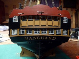
And this is how the stern looks with the strip glued in place:

PICT_V_6203
pict_v_6203.jpg

I was quite happy with things at that point but it was only after I’d taken and viewed the above picture that I realised how wavy the curve was! I should have glued the strip on first and then glued the columns on afterwards.
Fortunately, the kinks are only noticeable in the photograph!

Next job was to fit the trim on quarter galleries. I remember reading a post saying that bending the railings to fit properly was quite difficult. In the event, I didn’t have any significant problems and they fitted reasonably well.
There are some etched decorations that fit alongside the windows and I’ve also seen at least one post saying that there wasn’t room to fit these as shown. In this case, I had the same problems. In the end, I did manage to squeeze them in (but maybe they accidentally got transposed in the process). The one that caused the problem is visible in the following picture:

PICT_V_6204
pict_v_6204.jpg

Although the stripes for the ‘Nelson Chequer’ are pretty much as per the drawings, they didn’t really look right to me where they met the galleries so I decided to do a bit of realignment:

PICT_V_6205
pict_v_6205.jpg

Feel free to express your opinions on the change, but the captain likes it and his decision is final. (The admiral wasn’t consulted!)
The yellow ochre wasn't changed, only the lighting. Picture 6204 is nearer the actual colour.
 
Last edited:
Time to do some work on the ‘engines’. I’ve made a start on the main one, in other words, the main yard.
This is made from a length of 8mm dowel which is made octagonal in the centre section and then tapered down to 5mm diameter at the ends. I planed and sanded a flat on one side of the centre section and then clamped it in the vice with the flat against one of the vice jaws. That allowed me to plane across the top making another flat at 90 degrees to the first one. Turning the dowel over and repeating the procedure meant I now had flats each side and I could clamp it between these sides to shape the fourth side.
The small bench vice I have has horizontal vee grooves in each jaw which allowed me to hold the dowel with it rotated 45 degrees to start forming the octagonal shape. (No clever measurements, I just positioned it by eye.)
It was then just a case of progressively sanding each face until they were all the same width and they met at a sharp corner. The mahogany dowels seemed a little soft so I tried varnishing them to get a sharper finish, which seemed to work well. I afterwards thought that maybe I should have just used sanding sealer so when I shaped the stunsail booms I tried that instead. That also worked, but I think the varnish actually did a better job.
I used a small block plane to taper the yard, followed by a sanding stick to smooth things off.
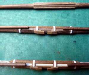
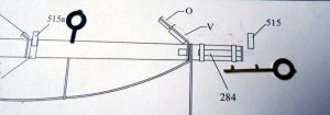
Next job was to make up the fittings for the stunsail booms. There are some photo etched brass parts provided for these. They’re probably as good as can be achieved using etchings, but I didn’t particularly like the pieces that fit around the booms. The bases that fit to the yard are fine:

PICT_V_6301
pict_v_6301.jpg

Note: The base for part 515a, the inner fitting, is shown as part 288 on the plans. It should be 286.

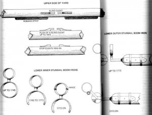
Looking at Lees diagrams, this is how they were constructed:

PICT_V_6302
pict_v_6302.jpg

(The two bottom right, post 1773, drawings are the relevant ones.)

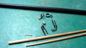
I opted to make up some new fittings using brass strip, but I drew the line at fitting a roller in the base of the outer one!
The straps on the outer fittings were much longer than those shown on the plan and have been cut to length and drilled to allow me to rivet them in place.

PICT_V_6303
pict_v_6303.jpg

I did take some pictures of the completed yard but the phrase ‘How to Find a Black Cat in a Coal cellar’ springs to mind.
Not a great success!

PICT_V_6304
pict_v_6304.jpg

Instead, here are some close ups, starting with the centre section and showing the octagonal section and the sling cleats:

PICT_V_6305
pict_v_6305.jpg

This is a view from under the front of the yard (the stunsail boom fittings are angled forward at 45 degrees):

PICT_V_6306
pict_v_6306.jpg

And finally, a view looking down on the front of the yard:

PICT_V_6307
pict_v_6307.jpg
 
Last edited:
Although I’d made one yard, I wasn’t intending to rig it at this stage: my intention was to construct at least all the lower yards and rig them all together. That left one minor problem, where to put the yard in the meantime. The obvious answer was on the ship so I decided to make up the sling and hang it temporarily from that.
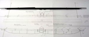
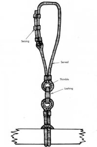
I was expecting to find details of the sling on one of the rigging plans but at first I couldn’t find it. After a more careful search, I found it shown in the following diagram:

PICT_V_6401
pict_v_6401.jpg

Not the most informative picture and the line size ‘C’, which is 0.75mm, seemed rather small to me.

This is what Petersson shows for the slings:

PICT_V_6402
pict_v_6402.jpg

From past experience I know that the hardest part of modelling this type of rigging arrangement is making the closed loop and getting it the right length. I found a good way of making a loop during my previous builds but I refined the technique a little in my latest attempts.
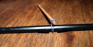
The first problem is to get the length of line right so as to end up with the correct sized loop. I used a length of wire to form the correct configuration of loop and cut off the excess:

PICT_V_6403
pict_v_6403.jpg

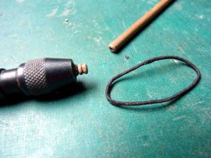
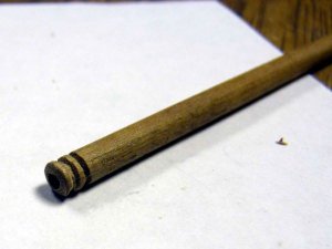
The length of dowel at the top that it’s wrapped round is what I’m going to use to make the thimbles.
I drilled a hole down the centre of the dowel and then carved a couple of grooves around the end. I continued deepening the second groove until the end section separated.

PICT_V_6404
pict_v_6404.jpg

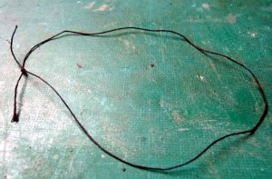
The next step was to measure the length of the piece of wire and tie a loop of cord exactly four times that length in circumference.
Not the most exciting picture but note that the knot is a simple overhand knot with the ends left a reasonable length for later:

PICT_V_6405
pict_v_6405.jpg

The loop was then given a half twist to double it up. Stretched out there are four strands side by side and the overall length is the same as the wire, in this case 90mm:

PICT_V_6406
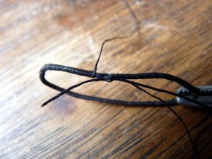
pict_v_6406.jpg

The next step is to serve the four strands with the knot at one end. The two loose ends are on the right in the following picture:

PICT_V_6407
pict_v_6407.jpg

When the serving is complete, the two ends from the knot are sticking out at one end and the strands form a small loop at the other end. A respectable length of the serving cord is left on at one end.
The next step is to pass one of the ends from the knot through the loop at the other end and tie it to the other free end so as to form a loop:

PICT_V_6408
pict_v_6408.jpg

I applied some glue to the knot and after it had dried, trimmed off the loose ends and served over the joint. The final bit of serving has to be done by hand, but it’s only a short length.
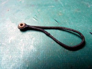
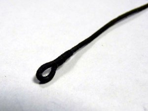
The following picture shows the completed loop together with the thimble. The thimble is simply pushed over the end of the drill which has been reversed in the pin chuck to hold it for final shaping:

PICT_V_6409
pict_v_6409.jpg

The final job on this piece of the sling was to seize the thimble into the loop. You can see that the joint in the loop is visible as a slightly fatter section but the original would have been spliced together at this point so it too would have been fatter at the joint.

PICT_V_6410
pict_v_6410.jpg

Here’s how it looks fitted to the yard:

PICT_V_6411
pict_v_6411.jpg

The top section of the sling is fairly straight forward. Rather than the 0.75mm cord (unserved?) shown in the plans I used 1.3mm cord. The cord was served as near to the end as possible, but the serving line wasn’t cut off. The cord itself was cut a few millimetres beyond the end of the serving and the strands progressively trimmed away over the exposed length. Glue was applied to these strands and they were folded back and the serving was continued over them to form an eye:

PICT_V_6412
pict_v_6412.jpg

The last jobs were to seize another thimble into this section of the sling and then to thread the tail of the sling through the eye and seize it to itself The latter job has to be done with it in place on the ship but at least it can be pulled up out of the top to complete the seizings once the correct length has been determined.
Here’s how it looks:

PICT_V_6413
pict_v_6413.jpg
 
Last edited:
Progress has been on hold for various reasons since my last entry; in fact, looking at the dates, it’s just two months today.

There’s not a lot to report but I’ve now constructed the lower yards for the main and mizzen masts.
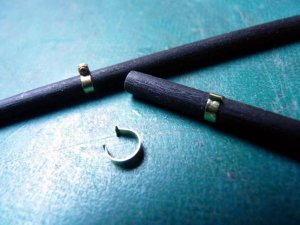
I modified the construction of the inner stunsail boom irons on the main yard. The ones for the fore yard were made by soldering a strip of brass into a ring, drilling a hole in the ring and soldering it to a brass support rod and then soldering on two short lengths of wire to represent the hinge and clamp. With all that soldering, it was easy to unsolder the original joint forming the ring which meant virtually starting from the beginning again.

This time I bent the ends of the brass strip such that I could crimp them together to represent the clamp. Soldering them was just added security.

PICT_V_6501
pict_v_6501.jpg

Despite what I said in a previous log entry, I decided I would include the roller in the outer fitting this time.
Here’s how they turned out.

PICT_V_6502
pict_v_6502.jpg

A short while ago, Bob (RMC) said in his log that one of the yards had sixteen sides rather than eight but, when he’d shaped it, it was almost impossible to see it wasn’t simply round.
I looked at my plan and all the yards were shown to be eight side, so I scratched my head and promptly forgot about it. When I came to make up the mizzen (crossjack) yard I at first couldn’t see the diagram for it. I then found it was on the next plan – and had sixteen sides!
Despite Bob’s comment, I decided to shape it as per the drawing. I cut a piece of 8mm dowel of the appropriate length from the stock provided. Next problem was how to get sixteen sides. I’d managed to create the eight sided sections by first planing four flats on a dowel at 90 degrees to each other and then planing an additional flat between two of these by rotating the dowel 45 degrees. The final three were then planed at 90 degree intervals from this one.
All I had to do was repeat this final stage to put an extra eight flats on the dowel, easy.
Oh no it wasn’t!
The flats on the fore and main yards were approximately 3.5mm wide; those on a sixteen sided yard were probably going to be under 2mm wide so I only planed a small amount off in creating the initial eight sided section. At this point it was almost impossible to see where the next flats should be as the edges of those already created weren’t sharply defined.
I needed some way to measure the angle I was turning the dowel through with reasonable accuracy and decided to stick a needle in the side of the dowel. The sensible place to do that seemed to be where one of the stirrups for the footropes was located, so I measured out the appropriate position – and found that my dowel was too short!
After a few moments head scratching, I took my eight sided off-cut of dowel out of the vice, retrieved the correct piece of dowel from the stock and started again!
This time I resorted to a bit of origami with a couple of post-it notes and was able to clamp the dowel at any of the required angles to put a flat on the upper surface:

PICT_V_6503
pict_v_6503.jpg

That worked remarkably well but I think Bob was right, it’s not worth the effort.
This is a close up of the yard in position and it’s hard to make out the flats. There are sixteen of them on there –honest!

PICT_V_6504
pict_v_6504.jpg

This last photo was just to get an idea of how the ship’s looking with the yards temporarily hung in place. Even without the stunsail booms in place (which do stick out further even in the retracted position) things have suddenly got a whole lot wider:

PICT_V_6505
pict_v_6505.jpg

I think the next step will be to rig these three yards (the yards only, not the lifts, braces etc at this stage.)
 
Last edited:
As per the comment in the last progress report, I’ve now rigged the lower yards. There are lots of blocks on those yards!
This is how it’s looking now:

PICT_V_6601
pict_v_6601_.jpg

The yards are only hooked onto the slings with short pieces of wire at the moment.

The stirrups for the footropes are supplied as photo-etched parts and I didn’t really fancy using those, but I thought I’d at least give them a try. After rounding the edges with a small file and blackening them, they turned out much better than I expected. I can forgive them for not quite looking as though there made of rope in view of the fact that they hold the footropes in the correct place and make them hang nicely.

PICT_V_6602
pict_v_6602_.jpg

These are the individual yards:

PICT_V_6603 - Fore yard.
pict_v_6603_.jpg

PICT_V_6604 – Main yard.
pict_v_6604_.jpg

PICT_V_6605 – Crossjack.
pict_v_6605_.jpg

I quite like this view, it’s a close up cropped from the first image:

PICT_V_6606
pict_v_6606_.jpg

I’m now working on the driver boom and gaff. They’re a bit more straightforward.
 
Last edited:
After a long interval with minimal progress, it’s time for an update.

I’ve now, more or less, completed work on the driver boom and gaff as promised in the last entry. The ‘more or less’ comment refers to the parrals which I’ve not yet fitted. I’ll leave those until I actually fit the spars to the mast.
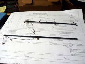
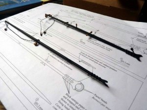
Here’s how they look at this time:

PICT_V_6701
pict_v_6701.jpg

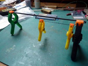
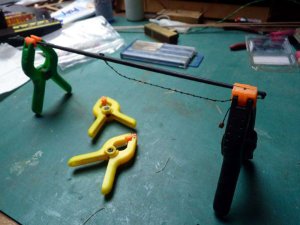
There’s a footrope on the driver boom and I recently suggested to Mike that he wet his footropes and hang some weights on them to get them to hang nicely. In return I received the suggestion of using small spring clamps as the weights – fair exchange!

PICT_V_6702
pict_v_6702.jpg

This is how it looked when things dried out:

PICT_V_6703
pict_v_6703.jpg

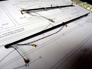
The various blocks are identified by letters, the majority of those on these two spars being letter N – 3mm single blocks. There’s an eyelet in the end of the gaff, but no block shown there, just a letter N. I nearly missed that one. I actually fitted the eyelet without the block and it’s much easier to seize an eyelet to a block before inserting the eyelet, but it was easy enough to remove it to do the seizing.
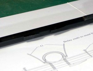
The other thing I missed was my fault, not an omission on the plans. The plans are on large sheets and take up a lot of room when opened fully. If you look at the first picture, you can see that these two spars are conveniently fully displayed by just turning over Plan 6 without unfolding it.
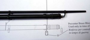
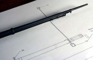
Well, actually, not quite! Although all of the driver boom is visible, the note telling you to drill a hole through the boom as a sheave for the out-haul is over on the other side. I’d looked at the eyelet at the forward end of the boom a few times thinking it was to attach the sail, but wondering why it was on the underside, so I had a look ahead through the plans where all was revealed.
Well almost all, I still haven’t figured how the driver boom is supported. The sail is lashed to the gaff and to sail rings round the mizzen mast – which I haven’t fitted!
However the only attachment along its lower edge appears to be the out-haul. There’s no saddle shown on the mast to support the boom jaws so I can’t see how the boom is to be held up.
I think I’ll have to get the books out for the rigging in this area.

Here are a couple of slightly better pictures of the two spars, but the details are still not all that easy to see:

PICT_V_6704
pict_v_6704.jpg

PICT_V_6705
pict_v_6705.jpg
 
Last edited:
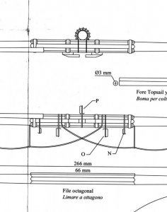
I've just started work on the topsail yards and I'm scratching my head over the drawings. I've even read the instructions! (There's desperate!)

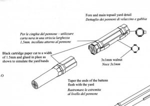
At first glance, it's simply a matter of filing the centre sections of the yards octagonal as shown in the bottom of these three diagrams of the fore topsail yard:

PICT_V_6801
pict_v_6801.jpg

Even ignoring the fact that the resulting octagon in that diagram is shown to be 6 mm across flats (starting with a 6 mm dowel) it bears no resemblance to the upper two diagrams showing the completed yard. These seem to indicate a built up centre section.
The bit that makes no sense to me whatsoever is the detail of the retaining bands. The diagrams imply that the four strips that lie at 45 degrees to the axis of the yard are applied first with four broad retaining bands. Next the other four strips are fitted with four narrow retaining bands centred over the broad bands.
(The top drawing shows the two middle narrow bands running under the top strip whereas the middle drawing shows them passing over it. The diagrams for the main topsail yard don't have this error.)

At the moment I'm at the stage of having shaped the fore and main topsail yards and am thinking in terms of building up the centre sections, but simply using four bands round all the strips - unless anyone has a better idea?
 
Last edited:
The plans for Vanguard (there are 20 of them, 1 x A0? & 19 x B1) are on the large side to spread out on the desk so I generally try and fold them to just show the part that I’m working on.
That’s where I went wrong this time!
I’d folded the plan back on itself down the centre line. This is what was on the other side:

PICT_V_6901
pict_v_6901_.jpg

There are four, rather than eight, strips fitted to the yard. What I’d taken to be broad yard bands are actually filler blocks fitted between the strips to support the ‘narrow’ yard bands.

Victory Models did get the drawing of the middle two yard bands wrong where they cross the top strip (the drawings for the main topsail yard are correct), but the rest of the confusion was all my own doing!
 
Last edited:
Now that I understand the drawings, it’s time to see about constructing something that looks like those yards.

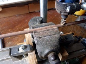
I decided to be a little more professional this time and actually machine the octagon sections in the middle of the yards. This is the set up:
PICT_V_7001
pict_v_7001.jpg

If you look at the right hand end, you can see the piece of piano wire stuck in the yard that I used to check the angle.
The actual machining was a success and I could cut a flat quite quickly. The same couldn’t be said for the time taken to set the yard level in the vice though! The overall time taken was significantly greater than just planeing and sanding them by eye and there was very little difference in the finished dowels. I reverted to hand tools after finishing the flats on the first yard.
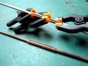
The next step was the easy bit, glue four strips on each yard:

PICT_V_7002
pict_v_7002.jpg

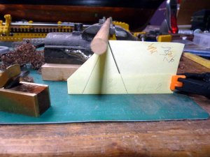
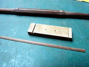
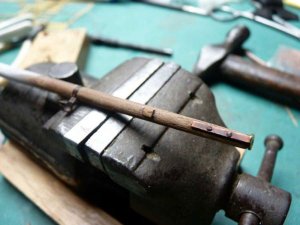
Cutting the filler pieces was a bit fiddly so I opted to shape a long strip and slice off the pieces one at a time. I used the same piece of MDF as I’d used to square up the edges of the deck planking to hold the strip, but this time I cut the slot at 45 degrees. With a piece of 3 x 1 mm strip dropped in the slot, I could sand one edge at 45 degrees. Having done that I turned the strip over and sanded just the end section of the other side at 45 degrees and then checked it for fit. I progressively sanded this end down until it fitted the yard. Once it fitted, I cut the slot in the MDF deeper until the end section of the strip fitted with the edge flush with the top of the MDF. I could then sand the rest of the strip flush to get a consistent width filler strip.

PICT_V_7003
pict_v_7003.jpg

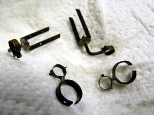
Time for some more stun’sail boom irons. The ones I made for the lower yards were quite fiddly to solder and a bit delicate so I decided to revert to the design I used on Astrolabe.
These were made by cutting a 1.5 mm brass strip and first bending it to fit under the forward quarter of the stun’sail boom and then down and around the yard:

PICT_V_7004
pict_v_7004.jpg

With the strip soldered together above the yard, the rest of the section around the boom could be shaped and then soldered at the front edge.

PICT_V_7005
pict_v_7005.jpg

Finally, a short length of 0.5 mm brass wire was soldered across the strip behind the boom to represent the hinge. You can't see it in the pictures but, honest, it is there!
This is how they look in position, but they still need to be blackened and I can’t complete the yards until that’s done and they’re fitted properly.

PICT_V_7006
pict_v_7006.jpg

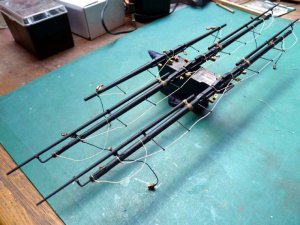
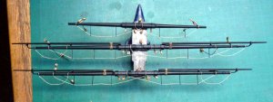
Here’s how the yards look at the moment:

PICT_V_7007
pict_v_7007.jpg

And this is a closer view of the centre sections of the three topsail yards:

PICT_V_7008
pict_v_7008.jpg
 
Last edited:
Another level completed (more or less). In this case, the topsail yards. The ‘more or less’ qualification is because I will need to fit the parrals when come to fit them on the masts.
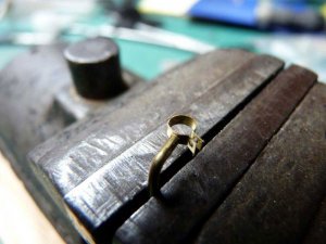
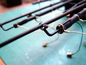
I’ve made yet another change to the way I constructed the stunsail fittings. This time to the fittings at the ends of the yards. Although the ones I made for the course yards looked OK, they were rather delicate and if I accidentally broke the hoop from the brass rod (which I managed to do on a couple of occasions) it was almost impossible to hold them together in the right positions whilst I re-soldered them.
I took a picture of my kit of parts for the new fittings but I seem to have accidentally deleted it. Instead you’ll have to make do with a picture of one that failed the quality control standards:

PICT_V_7101
pict_v_7101.jpg

In practice, once I’d got the length and the hole spacing worked out, I used that one as a template to drill the other three.

The first step was to put a 90 degree bend in the brass rod. Getting that in the right place was probably the hardest part. Riveting the strip on the rod was surprisingly easy:

PICT_V_7102
pict_v_7102.jpg

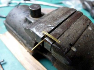
The two ends of the strip were bent outwards and the strip was curved round:

PICT_V_7103
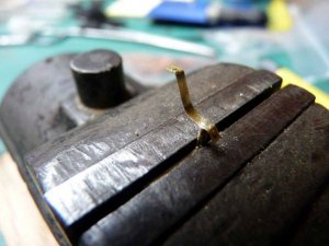
pict_v_7103.jpg

This is the completed shape. A short piece of brass tube will form the roller as per the previous versions. (Yes, I did remember to make two left-hand and two right-hand versions!

PICT_V_7104
pict_v_7104.jpg

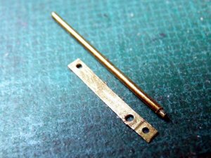
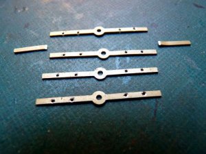
The next parts to receive attention were the photo etched straps that fit round the ends of the yards. These were much longer than those shown on the plans. This is how they looked cut down and with countersunk holes ready for riveting on the yards:

PICT_V_7105
pict_v_7105.jpg

And this is how they looked a few minutes after that:

PICT_V_7106
pict_v_7106.jpg

With the straps in place, I could drill the ends of the yards to accept the other parts of the fittings and fit everything together:

PICT_V_7107
pict_v_7107.jpg

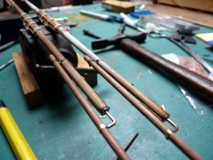
After I’d lined up the stunsail booms, I soldered the brass rods to the straps and reached for the blackening solution and the black paint:

PICT_V_7108
pict_v_7108.jpg

Looks like I need to touch up the ends of that strap!

Here’s how they look after painting and with their iron bands, blocks and footropes fitted:

PICT_V_7109
pict_v_7109.jpg

PICT_V_7110
pict_v_7110.jpg
 
Last edited:
After a rather long interval, I’ve now completed the rest of the yards.
These included the spritsail yard which is another one that’s centre section is sixteen sided. I’ve tried various methods to shape the centre sections of the yards with reasonable success but this time I tried yet another variation that turned out to be much simpler and quicker and actually seems to have been more accurate. Basically, I did it by eye!
As before, I simply filed one flat to start with. The dowel is 6mm diameter so about 1mm wide seemed a reasonable estimate. The major difference was that this time I ran a black marker pen along the flat section so I could see it!
I clamped the dowel in the vice and filed the two flats at 90 degrees followed by the one at 180 degrees and marked those also. I then filed the next four midway between them by eye and coloured those also. At that stage I had eight flats all coloured black and it was very easy to see where the remaining eight flats should be. Once I’d filed those flats, I had a length of dowel with a centre section having sixteen alternatively coloured black and white stripes.
At that stage I did take a picture but managed to delete it from my camera before I’d copied it to my PC. However, I did realise I’d done so and managed to recover it. I’ve just looked for it and I can’t find it! You’ll just have to take my word for it that it worked.
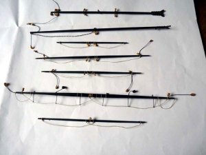
Instead, here’s a picture of the remaining yards:

PICT_V_7201
pict_v_7201.jpg

Not a stripe to be seen.

There are a couple of lines shown leaving the ends of the spritsail topsail yard and the mizzen topgallant yard for destinations as yet unknown. I suspect these to be braces but they can be easily attached later as they are the outermost items on the yards.
 
Last edited:
I found an off-cut of 6mm dowel so I spent a few minutes with a file and marker pen to show how it looked.
It probably took less than 10 minutes.
demo.jpg
 
Last edited:
Hi Arthur,
I am speechless. This is stunning workmanship. I am very thankful that you are posting your build of the Vanguard on SOS for us. I love the Vanguard and had thought about building it. Instead I chose the San Felipe. Well, when I get to the Vanguard, I have someone to follow. However, I can't say that mine would turn out as stunning as this.
I love your serving machine. I wish I could see a video of this in action.

Donnie
 
Haven't you got that backwards? I should be thanking you for providing somewhere to publish my log.

As far as a video is concerned, I'll see what I can do once I've posted the rest of this log'
 
For a while I’ve been considering fitting furled sails on Vanguard so, having completed the yards, I decided it was time to do I little experimenting.
The problem was always going to be one of scale. At 1:72 scale, the sails probably need to be something like 0.05 mm thick and I’m fairly obviously not going to come anywhere near that. There is some sail material supplied with the kit; it’s quite nice and I could probably get away with using it for full sails, but not furled ones. It’s just under 0.2 mm thick. That’s around 13 mm or ½” thick at full size.
A furled sail should, at most, be a similar diameter to the yard and I’ve seen sails cut down in size in an attempt to achieve this. As a quick test I tried some thin paper and found I could make a roll of a reasonable size but I certainly wasn’t going to find any cloth that thin. It was fairly obvious that unless I resorted to something like tissue paper, I couldn’t get it small enough and still have some sort of realistic shape rather than a plain white rod.
So, no sails it is then.

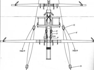
Next step seemed to be fitting the yards so I had a look at the plans. At first I only found the diagram for the fore mast but I was sure I’d seen a drawing for the main yard:

PICT_V_7301
pict_v_7301.jpg

For some reason it’s on the diagram for the masts rather than the one for the yards:

PICT_V_7302
pict_v_7302.jpg

The first minor problem of what was to become a pretty disastrous day arose at that point.
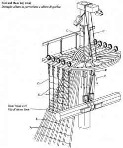
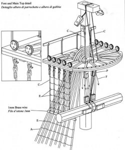
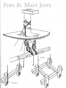
The diagram for the fore jeers shows a strap round the mast top with an eye splice in each end, no problem so far. However the jeer blocks are on a pendent at the top of which is an eye splice which loops through the two eyes on the strap. That meant that to replicate that, I should have fitted these much earlier and now I would either have to lift the mast cap up to loop the assembly over the mast top or make up the eye on the jeers in situ.
The diagram for the main jeers is different. It shows a long pendant made off with a loop around the mast top, which seemed a more practical arrangement.
Lees shows something similar with the end of the pendant spliced into a loop large enough to fit over the mast top.
I had a look at Petersson’s diagram which shows yet another arrangement and which I used on Astrolabe.

PICT_V_7303
pict_v_7303.jpg

I should be able to lift the mast caps up and if so I’ll probably go with the method Lees describes, otherwise it might end up similar to Petersson’s drawing.

At this stage I checked to see how the jeers were rigged. There was no line number given for the main jeers but the fore jeers were shown as line 16 and the belaying plan showed line 16 on the fore bitts. It also showed line 17 on the main bitts so I’m assuming line 17 is the main jeers.
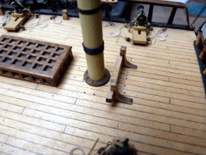
When I looked at the main bitts I realised I hadn’t drilled any holes in them, (The jeers normally run through a sheave in the bitts as shown in Petersson’s diagram). At this point I found my next problem. The deck around the main mast was nice and clean and tidy (as was the deck around the mizzen mast). Thing is, it shouldn’t have been! There should be a forest of eyelets at the foot of each mast. The ones around the fore mast were all present and correct but, for some reason, those around the other two masts were conspicuous by their absence. In rectifying this, my day was about to get a whole lot worse!
Fitting eyelets in the deck is a relatively simple task - without the standing rigging in place. It’s much more of a challenge with the shrouds in the way. This is how the foot of the mizzen mast looked after a bit of work with a drill:

PICT_V_7304
pict_v_7304.jpg

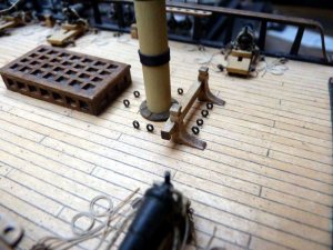
I’ve probably posted this picture before but these are some eyelets from my Gulnara kit supplied by Krick. They’re already blackened and are smaller than Amati’s version. A little snipping and bending made them even smaller:

PICT_V_7305
pict_v_7305.jpg

And this was the result:

PICT_V_7306
pict_v_7306.jpg

Next job was even more of a challenge, drilling through the foot of the main bitts. This was where my day went from bad to very much worse.
I accidentally knocked one of the fire buckets off the rack. Not a major problem? It is when it bounces on the deck and disappears down the stairs to the lower gun deck!
After peering through the gun ports, poking a lit LED down the stairs and again peering through the gun ports, tipping the ship on its side, shaking it and once again poking a lit LED down the stairs and peering through the gun ports - you get the picture - no sign of it. Time to make another fire bucket.
A bit of drilling, carving, filing and painting was surprisingly successful, so had I finally overcome my problems? Not a chance, things were about to get even worse!
Actually, they already had, it’s just that I hadn’t realised it at this stage. When I came to hang up my new fire bucket, there was no hook to hang it on. It hadn’t fallen off the hook, the hook had come out. As things stood at that moment, getting access to the rail meant that the chances of me refitting a hook that small were more or less zero.
So after a little brute force and finesse, I improved the access and my chances:

PICT_V_7307
pict_v_7307.jpg

Honest captain; it just sort of fell off…

The hook is actually bent from 0.3 mm brass wire and the ends of each hook have, as far as possible, been closed up to stop the buckets falling off but they are obviously not strong enough to withstand even a minimal amount of force.
Anyway, things are now more or less back to where they should be:

PICT_V_7308
pict_v_7308.jpg
 
Last edited:
Back
Top