Looks like a nicely detailed and lovely model.
-

Win a Free Custom Engraved Brass Coin!!!
As a way to introduce our brass coins to the community, we will raffle off a free coin during the month of August. Follow link ABOVE for instructions for entering.
-

PRE-ORDER SHIPS IN SCALE TODAY!
The beloved Ships in Scale Magazine is back and charting a new course for 2026!
Discover new skills, new techniques, and new inspirations in every issue.
NOTE THAT OUR FIRST ISSUE WILL BE JAN/FEB 2026
You are using an out of date browser. It may not display this or other websites correctly.
You should upgrade or use an alternative browser.
You should upgrade or use an alternative browser.
HMS Vanguard 1787 - Victory Models - 1:72 [COMPLETED BUILD]
Thanks Gary.
After my copy and paste fingers have recovered, I'll see about writing the next two entries.
After my copy and paste fingers have recovered, I'll see about writing the next two entries.
I know I said I needed to install the driver boom but, as usual, there was another job (well, two actually) that I needed to attend to first.
I’d started installing the braces at the pointy end and worked back towards the blunt end - except, actually, I didn’t.
I’d started too far back and missed the jib braces!
Nothing particularly complicated with these, but yet more lines to make off on the fore rail. I suppose that in practice, where more than one line was made off, the running rigging would at least be on top!
It was when I came to fit the braces to the jib topsail yard that I realised I’d another job to do. Once again, some things were conspicuous by their absence; in this case they were the yard lifts.
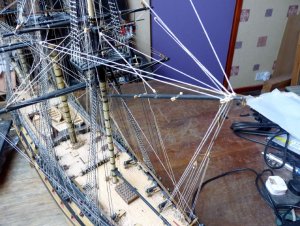
This is how the pointy end rigging looks now:
PICT_V_9001
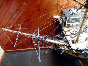
PICT_V_9002
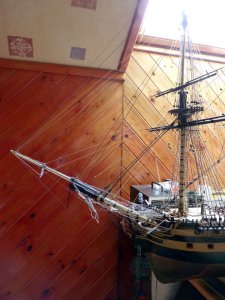
I think that completes all the bowsprit rigging.
It’s to be hoped so, because this jumble of knitting is where most of it starts or ends:
PICT_V_9003

I’d started installing the braces at the pointy end and worked back towards the blunt end - except, actually, I didn’t.
I’d started too far back and missed the jib braces!
Nothing particularly complicated with these, but yet more lines to make off on the fore rail. I suppose that in practice, where more than one line was made off, the running rigging would at least be on top!
It was when I came to fit the braces to the jib topsail yard that I realised I’d another job to do. Once again, some things were conspicuous by their absence; in this case they were the yard lifts.
This is how the pointy end rigging looks now:
PICT_V_9001

PICT_V_9002

I think that completes all the bowsprit rigging.
It’s to be hoped so, because this jumble of knitting is where most of it starts or ends:
PICT_V_9003

Last edited:
This model kit is definitely on my wish list! I have been lobbying the plastic model manufacturers to create a kit of this ship but they are not listening. You have done a great job so far! Very impressive.
Bill
Bill
Thanks Bill.
If you want a model of Vanguard it looks as though you'll have to create wood shavings and sawdust instead of empty plastic sprues!
If you want a model of Vanguard it looks as though you'll have to create wood shavings and sawdust instead of empty plastic sprues!
I think that I'll buy the kit by Victory Models. The plastic manufacturers have no real interest in helping the sailing ship model industry. That is okay; I have made the transition to wood. The Vanguard is one of my favorite ships!
Bill
Bill
It’s been a long time since my last update as various other things have taken precedence, but when I came to add a new entry for the jib boom and gaff, I realised I’d also missed an update!
For quite some time the stern facia has been sitting on the shelf behind me, more or less complete.
PICT_V_9101
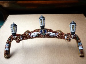
I hadn’t fitted it because I have a habit of bumping into anything that sticks out, and the lanterns looked like a prime candidate.
As the next job was going to be fitting the jib boom, that was going to stick out even further, so fitting the lanterns (and hence the facia) seemed to be next on the list.
At this point, the lanterns were only a push fit in the resin casting so they needed soldering to the connecting wires I’d embedded in the casting, I’d used some stiff white wire for the lower leg of the lanterns so before I soldered the connections, I removed the lanterns and painted the wire black, (That worked much better than I expected.)
The photographer obviously took a holiday around this time as in the next pictures, the facia has magically epoxied itself to the transom; however, this is what the back of it looked like quite a while ago:
PICT_V_9102

The legs of the centre lantern and the two inboard legs of the outer lanterns (the negative connections) were soldered to the connecting wires which held them firmly in position. I made a little ring of wire to go round each end of the outer legs and soldered each of these too. The two outer white wires are bent inward and lie in the groove you can see before being bent forward like the middle leads.
Another old picture here shows where it’s going:
For some reason, I’d decided the top of section should be painted red. In fact, only the bottom centre of that area needed painting, and it should actually be black!
It is now:
PICT_V_9103
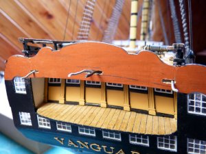
The one photograph I should have taken was of the connections. It was a case of sliding short lengths of sleeving over the three positive leads and soldering them to the white leads from the casting. I didn’t need to sleeve the black lead. The wires pushed back into the transom and, although they’re theoretically visible under the ceiling, they can’t be seen.
It was actually much easier to clamp the casting in place than I expected and I must have decided it wasn’t worth photographing, so here’s how it looks in position – with a little bit of a sneak preview of the driver boom:
PICT_V_9104
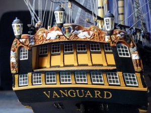
I don’t think I need a safety rail around that stern platform as there doesn’t seem to be anyway of getting on to it!
(But I’ll fit one shortly.)
And another view of things:
PICT_V_9105
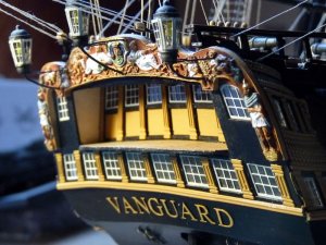
When I first fitted the lanterns in the casting I wasn’t sure I could make the connections below the level of the poop deck and I was considering hiding the wires with the knees to the transom.
So I could now fit the knees (and a deck cleat for the spanker boom sheet):
PICT_V_9106
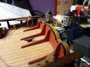
I also needed an eyelet between the cleat and the transom, but that’s the next instalment.
The picture also shows a mistake I only noticed later; the nicely coiled line on the belaying pin shouldn’t be there, it should be made off on the cavel cleat in front of the pin rail. At least It’s a real rope coil so I was able to uncoil it and transfer it.
As you can see, the edge of the plywood transom was originally painted black. I considered repainting it red or yellow ochre but decided I liked it black where it runs down to the stern galleries so I’ve left it black all the way.
And yes, it all works:
PICT_V_9107

For quite some time the stern facia has been sitting on the shelf behind me, more or less complete.
PICT_V_9101

I hadn’t fitted it because I have a habit of bumping into anything that sticks out, and the lanterns looked like a prime candidate.
As the next job was going to be fitting the jib boom, that was going to stick out even further, so fitting the lanterns (and hence the facia) seemed to be next on the list.
At this point, the lanterns were only a push fit in the resin casting so they needed soldering to the connecting wires I’d embedded in the casting, I’d used some stiff white wire for the lower leg of the lanterns so before I soldered the connections, I removed the lanterns and painted the wire black, (That worked much better than I expected.)
The photographer obviously took a holiday around this time as in the next pictures, the facia has magically epoxied itself to the transom; however, this is what the back of it looked like quite a while ago:
PICT_V_9102

The legs of the centre lantern and the two inboard legs of the outer lanterns (the negative connections) were soldered to the connecting wires which held them firmly in position. I made a little ring of wire to go round each end of the outer legs and soldered each of these too. The two outer white wires are bent inward and lie in the groove you can see before being bent forward like the middle leads.
Another old picture here shows where it’s going:
For some reason, I’d decided the top of section should be painted red. In fact, only the bottom centre of that area needed painting, and it should actually be black!
It is now:
PICT_V_9103

The one photograph I should have taken was of the connections. It was a case of sliding short lengths of sleeving over the three positive leads and soldering them to the white leads from the casting. I didn’t need to sleeve the black lead. The wires pushed back into the transom and, although they’re theoretically visible under the ceiling, they can’t be seen.
It was actually much easier to clamp the casting in place than I expected and I must have decided it wasn’t worth photographing, so here’s how it looks in position – with a little bit of a sneak preview of the driver boom:
PICT_V_9104

I don’t think I need a safety rail around that stern platform as there doesn’t seem to be anyway of getting on to it!
(But I’ll fit one shortly.)
And another view of things:
PICT_V_9105

When I first fitted the lanterns in the casting I wasn’t sure I could make the connections below the level of the poop deck and I was considering hiding the wires with the knees to the transom.
So I could now fit the knees (and a deck cleat for the spanker boom sheet):
PICT_V_9106

I also needed an eyelet between the cleat and the transom, but that’s the next instalment.
The picture also shows a mistake I only noticed later; the nicely coiled line on the belaying pin shouldn’t be there, it should be made off on the cavel cleat in front of the pin rail. At least It’s a real rope coil so I was able to uncoil it and transfer it.
As you can see, the edge of the plywood transom was originally painted black. I considered repainting it red or yellow ochre but decided I liked it black where it runs down to the stern galleries so I’ve left it black all the way.
And yes, it all works:
PICT_V_9107

Last edited:
Looks great.
Thanks Gary.
Hi Mustafa, how's the Santa Maria getting on?
The log here has lost all its pictures.
The log here has lost all its pictures.
The Vanguard is looking great! I am learning a lot!
Bill
Bill
Time to bring the log up to date with the actual construction.
The final bits of woodwork to hoist aloft were for the spanker. The problem was that there was actually no way to hoist the inboard end of the driver boom! I’m sure it would be just fine hanging on the bottom of a sail, but – no sail…
So I needed a saddle for the jaw to rest on, something like this:
PICT_V_9201

PICT_V_9202
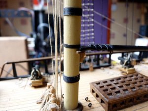
Here’s how it looks with the boom topping lifts and guy pendants rigged:
PICT_V_9203

The plans show the boom topping lifts made off on the mizzen bitts, but they’re pretty crowded already so once more I opted to follow the arrangement Petersson shows and fitted cleats each side of the mast:
PICT_V_9204

There’s even more rigging on the gaff:
PICT_V_9205
And here’s an overall view of the spanker rigging:
PICT_V_9206

I think that’s a major milestone, It completes the rigging!
At this point, I made a start on the list of little outstanding jobs.
In this case, a recent one, the stern balcony railing:
PICT_V_9207

This picture also shows where I fitted the eyelets for the driver boom guys and the vangs. After a check on the photo of the rear of the resin casting to see where the wires were, I drilled into the top of the casting.
The next catch-up job was to fit these chains on the rudder:
PICT_V_9208

This job actually left me puzzled. I looked through the instruction book to see where the chains were made off, but didn’t find them. I’ve added notes to my parts list showing which plan to refer to, but when I looked down the parts list I didn’t find any chain listed!
The chain in the picture is spare from my Gulnara kit. If there was any chain in the Vanguard kit, it’s not listed and I’ve lost it – but it is shown in the picture on the box!
The final bits of woodwork to hoist aloft were for the spanker. The problem was that there was actually no way to hoist the inboard end of the driver boom! I’m sure it would be just fine hanging on the bottom of a sail, but – no sail…
So I needed a saddle for the jaw to rest on, something like this:
PICT_V_9201

PICT_V_9202

Here’s how it looks with the boom topping lifts and guy pendants rigged:
PICT_V_9203

The plans show the boom topping lifts made off on the mizzen bitts, but they’re pretty crowded already so once more I opted to follow the arrangement Petersson shows and fitted cleats each side of the mast:
PICT_V_9204

There’s even more rigging on the gaff:
PICT_V_9205

And here’s an overall view of the spanker rigging:
PICT_V_9206

I think that’s a major milestone, It completes the rigging!
At this point, I made a start on the list of little outstanding jobs.
In this case, a recent one, the stern balcony railing:
PICT_V_9207

This picture also shows where I fitted the eyelets for the driver boom guys and the vangs. After a check on the photo of the rear of the resin casting to see where the wires were, I drilled into the top of the casting.
The next catch-up job was to fit these chains on the rudder:
PICT_V_9208

This job actually left me puzzled. I looked through the instruction book to see where the chains were made off, but didn’t find them. I’ve added notes to my parts list showing which plan to refer to, but when I looked down the parts list I didn’t find any chain listed!
The chain in the picture is spare from my Gulnara kit. If there was any chain in the Vanguard kit, it’s not listed and I’ve lost it – but it is shown in the picture on the box!
Last edited:
Hi Arthur,
What a beauty, so detailed.
I am amazed by the quality of the rigging you are making.
Definately your Lego based roping machine has my interest. I have to start rigging my Mamoli Friesland somewhere in the near future and this is putting the quality of the rigging to a much higher standard then the standard kit provided solutions, so I think I will give it a try.
Regs, Maarten
Hi Arthur,
Many thanks for the tip. Good quality rigging realy makes the model great.
I will definately build this.
A happy New Year and excellent 2018.
Regs Maarten
Many thanks for the tip. Good quality rigging realy makes the model great.
I will definately build this.
A happy New Year and excellent 2018.
Regs Maarten
What a great model. Very clean and well done. The rigging with proper size ropes makes the model look real and not just a jumble of lines. I aim to get over 15 sizes of lines on my models and it makes it not just look like another kit job, but a real quality model.
Thanks gentlemen.
Gary, not differentiating between line colours, there are probably only half a dozen different line sizes in use.
However, as per the comments from Maarten, seizing stays and shrouds where appropriate makes a big difference.
Gary, not differentiating between line colours, there are probably only half a dozen different line sizes in use.
However, as per the comments from Maarten, seizing stays and shrouds where appropriate makes a big difference.
G'day arthur, I've just had a very enjoyable read through your build log,very nice work, I particularly like the way you have painted the stern, and your lighting looks great, a very nice model,
best regards John.
best regards John.
Thanks John.
It's always nice to know someone finds it interesting.
It's always nice to know someone finds it interesting.


