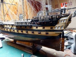
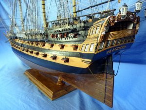
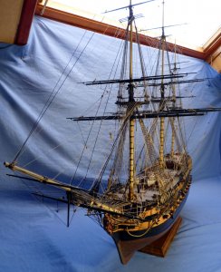
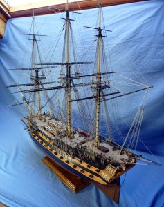
HMS Vanguard 1787 - Victory Models - 1:72 [COMPLETED BUILD]

John: The time they needed those booms was when there wasn't much wind and progress was slow, but I don't think dropping anchor(s) to get access to them would have been acceptable, :) so your comment that they were stowed elsewhere makes a lot of sense. (Do you mean alongside the hull in the area between the fore and main channels though, that doesn't sound right.)
They're not shown on the diagram, but that's not definitive because lots of other items aren't shown either.
However, there is a saddle at the aft end of the channel so they can be stowed as I have them fitted. I suppose I could have routed the rope slings down between the booms and the channels but the aft anchor would still be in the way.

Thanks Uwe, glad you like it.
 
Hello Arthur

Just catching up on your HMS Vanguard build, haven't been here for a while. Just love your solution for hiding the lighting wires for your Stern Transom, this idea of yours would work great on my Oliver Cromwell build that is if I ever get that far. You sure have shown a lot of solutions to a lot of problems in your build and have come up with some great ideas,

I believe that the solution for storing the Fore-Lower Studding Sail Boom is that to swing it out for use was to use was to use the topping Lift that was attached to the Boom, lift the outer end up to clear the Anchors and then swing it out and then lower it for use to secure the Studding Sail. I get this from Lennarth Petersson book on Rigging Period Ship and Model. On page 110 he said that the Fore Lower Boom was hooked into an Eyebolt in the ships side. This sounds very workable to me and I do hope that it helps you, ENJOY.

Regards Lawrence
 
Last edited:
G'day Arthur, I meant on the beams across the waist, I don't know what they have provided in the kit, but there is no saddle as you call it on the back of the fore channels, both Peterson and Lee's say there is an eye bolt between the cat head and the fore channel, which you can see in photos of the Victory, in which the lower jib boom hooked when being used, I saw a comment on MSW by one of the members that said the lower fore booms were stowed along with the spare spars and the boats on the beams across the waist,
Best regards John,
 
I was actually commenting on the fact that the slings for the anchors and the inboard flukes of the aft-most anchors go over the booms, However, it appears I've opened a can of worms!

First: where to stow them.
4 brackets and 4 'securing rings' were supplied.
There is a picture on the front cover of the instruction book that shows the port side boom mounted on the channel and they are shown there on plan 8. (But the anchors are conspicuous by their absence!)
The booms are longer than the open area under the ship's boats.

Where to fit them:
Petersson shows them fitted to an eye-bolt (on a frigate).
Lees says a plate on the channels or an eye-bolt just forward of the channels.
In the case of a three-decker, e.g. Victory, to an eye-bolt abreast of the fore end of the channels but just above the lower gunports.

So; where they should be is a uncertain; where they're staying, much less so!

Thanks for your input gents.
 
The kit includes a cradle to support the model, but it was always my intention to mount the model on a stand similar to my other models so screw holes were drilled in the keel early in the construction.

Many years ago (actually a generation ago) I made a pair of oak coffee tables:

PICT_V_9601
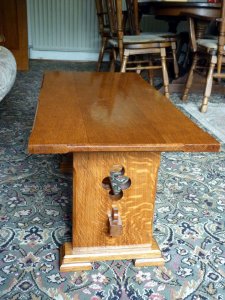
PICT_V_9601.jpg

If you look at the decorative cut out-in the leg, it was made by drilling four holes with a hole-saw. Four holes in each leg, two legs on each table and you end up with lots of these:

PICT_V_9602
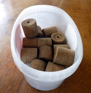
PICT_V_9602.jpg

If you have children, I’m sure you’re familiar with the scenario where you buy them an expensive present and they spend all their time playing with the box it came in!
The reason I know the tables were made a generation ago is that my children played with these off-cuts as building bricks and my grandchildren are now doing the same.
Well, they’ve now got two less to play with!
Here’s how two of them look after a bit of work with the lathe. They’re together with a piece of oak that’s had an encounter with the router table:

PICT_V_9603
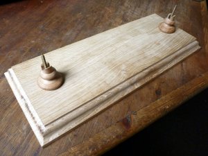
PICT_V_9603.jpg

You have to go all the way back to page 1 of this log to find the details of how the base fits to the keel. Vanguard is fitted with LED lighting and the power connection is via the mounting screws. (If you want more information on the lighting, there are a couple of articles in the ‘How to’ section on the Navy Board Models website.)

That called for some more machining of the base in order to mount a USB socket and connect it to the mounting screws:

PICT_V_9604
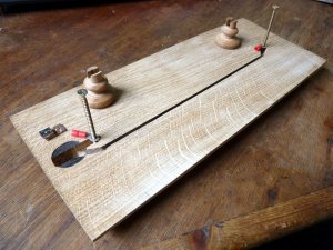
PICT_V_9604.jpg

The black circle at the left is not a design feature. If you want to machine a slot 18mm deep, you need to have at least 18mm of the cutter protruding from the collet! It didn’t seem to be cutting too well and applying a bit more pressure only resulted in smoke instead of shavings. Fortunately it’s the bottom side.
The object above the burnt area is a USB socket soldered to a piece of strip board (veroboard) to which the connecting leads can be soldered. It fits in the bottom of the slot, which extends out of the end of the base.

PICT_V_9605
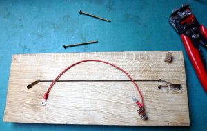
PICT_V_9605.jpg

Although the burnt area won’t show I opted to repair it.
The light coloured strip of wood visible in the slot holds the back end of the veroboard down and the little shaped block at the top right will be glued in the slot to hold the socket itself down. As a final security measure, a drop of epoxy under the board will stop it sliding forward when unplugging the lead. I didn’t want to use too much epoxy and have it squeezing into the socket.
Here’s how it fits:

PICT_V_9606
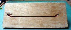
PICT_V_9606.jpg

Now you see it:

Now you don’t.
There are a couple of cross cuts over each screw hole, so the screws are accessible.

PICT_V_9607
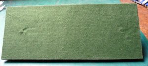
PICT_V_9607.jpg

This is how it looks right way up:

PICT_V_9608
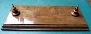
PICT_V_9608.jpg

This was the point where the real problem started; how to actually mount the ship on the stand.
I’d given this some thought and decided that although the new stand would just fit inside the cradle. I wasn’t prepared to risk suspending the ship over thin air with just 6mm of support at each end! I was quite happy to sacrifice the cradle though, and pretty sure it would come apart without much trouble so I called on my son for assistance.
Unfortunately there were no hands free to operate the camera so you’ll have to make do with an explanation only.

The first step was to slide the ship back in the cradle so the front mounting hole was near the middle of the cradle and the back mounting hole was well clear behind the cradle.
I could now lift the back of the cradle and swing it clear of the desk and slide the cradle back towards the edge of the desk so that I was supporting the stern, the bow was over the desk and the midship section was accessible.
At this point my son was able to screw the new stand into the keel, but not fully tighten the aft screw because the aft end of the cradle was now trapped in the area between the pillars of the new stand.
At this point it was possible to lift the front end of the new stand on to the desk so all was now secure. It was just a case of cutting, ‘ungluing’ or breaking free the rear section of the cradle. In practice, the two just broke apart fairly easily, releasing the cradle and the aft mounting screw was then tightened up.

Here it is on its new stand - and the lights work:

PICT_V_9609
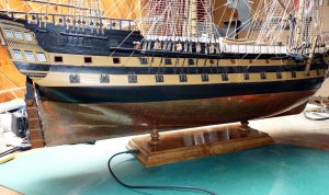
PICT_V_9609.jpg
 
Last edited:
Thanks Uwe.

Did you spot the link to the Navy Board Models site?
It didn't automatically display in blue and I couldn't manually set it to blue either, so I opted for italics.
 
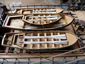
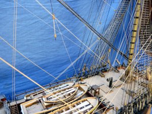
Vanguard’s four ship’s boats have been sitting, unsecured, in their cradles for some time. The time has come to sort out their fittings and lash them in position.

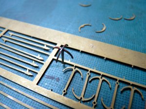
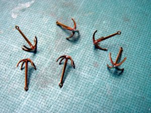
There are six kedge anchors supplied for the four boats, so that’s going to be two each for the two larger boats and one each for the other two.
Each anchor comes in two pieces which fit together very well, but I opted to solder the joints. Cutting the bottom end of each main piece free and bending it up held it nicely whilst that was done:

PICT_V_9701
PICT_V_9701.jpg

This little lot are destined for the blackening brew:

PICT_V_9702
PICT_V_9702.jpg

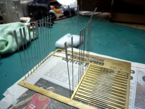
There are brass etchings supplied to equip the boats with oars, anchors and pikes so the first job was to paint the various parts. The base colour for the oars is white, with brown handles and copper tips to the blades. After my success in soldering the anchors, I got carried away, cutting the long oar blades free from the sheet and bending up each oar so I could paint it:

PICT_V_9703
PICT_V_9703.jpg

It seemed like a good idea at the time, but the results were less than inspiring. I reverted to spraying the short oars in situ in the sheet!
There are sixteen pikes supplied for the boats and those were also painted in situ.

There’s something odd about the numbers of oars supplied and described in the instructions.
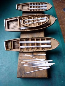
The long oars are for the launch and the barge and the instructions say twelve oars in each. That’s twenty-four oars, which is the number supplied. However the launch has fourteen rowlocks (well, notches in the sides) and the barge has ten so that’s the number of oars they’re getting.
The short oars are for the cutter and the pinnace and the instructions say six each. That matches the rowlocks of the cutter, but the pinnace has ten. That’s a total of sixteen and there were twenty-eight supplied!
Here are the boats kitted out – and a dozen spare oars:

PICT_V_9704
PICT_V_9704.jpg

Now for the day’s challenge, lashing them in position.
There’s no chance of accessing the eyelets with the boats in position so it was a case of threading the line through the eyelets first and then sliding the boats under the line.
This is how the line was routed:

PICT_V_9705
PICT_V_9705.jpg

And here they are lashed in position:

PICT_V_9706
PICT_V_9706.jpg
 
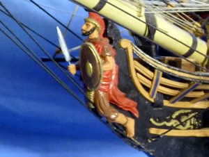
If you look back through the log, I’m sure you’ll find a picture similar to this:

PICT_V_9801
PICT_V_9801.jpg

There’s a subtle difference though; in the original picture he’s disarmed. The sword looked as though it could get knocked and broken so fitting it was added to my ‘to do’ list.
The significance is that it was the last outstanding item on the list. Vanguard if finally completed!

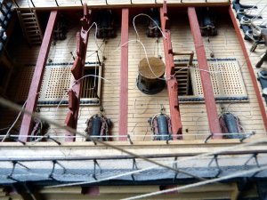
There are, however, some final steps to report that preceded that final piece of armament. The first of these was a somewhat more significant addition to the armament, namely all the guns on the port side main gun deck.
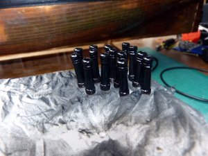
Here they are awaiting fitting:

PICT_V_9802
PICT_V_9802.jpg

They’ve just been sprayed matt black. I should have waited until the paint dried before taking the photograph; they look gloss black in the picture.

If you count them you’ll see there are fourteen of them. Things didn’t go to plan and I had to spray another one later!
I’d drilled the plywood strip and temporarily screwed all these in position some time ago so I knew they all fitted but when I came to finally install them I accidentally dropped one of them just inside the gun-port. I attempted to lift it out with my tweezers but it kept eluding me. It then disappeared from view! I’ve no idea where it went because there are no holes in that deck but fortunately, as I’d opted to have the starboard gun-ports closed, I had fourteen spares.

I’d also made up the gun-port lids at that time but although I’d fitted the hinges I still needed to fit the rings to them.
At this point I decided I’d been too clever for my own good. On the starboard side I’d rolled up the little tongue on the hinges and mounted them using little 0.3mm wire staples so the hinges actually worked. I’d also rolled up the tongues on the port side hinges. That was definitely a mistake! If I’d left them alone I could have simply drilled holes for them in the hull. I soldered short lengths of 0.3mm wire in each hinge to effectively get back to where I’d started. On the plus side, the 0.3mm wire bent easily allowing me to adjust the position of each lid.
Here’s how they turned out:

PICT_V_9803
PICT_V_9803.jpg


I thought I’d made all the lids but if you look at the deck above there are three gun-ports without lids. There are also three on the starboard side.
The three on that side weren’t a problem as I could easily cut pieces to fit the port. However those three in the picture have guns in the way. Cutting pieces to fit those was a bit of a challenge, particularly so because the wales run across those gun-ports.
At least the lids don’t need to actually fit, they only have to look as though they will! Like this:

PICT_V_9804
PICT_V_9804.jpg

The penultimate outstanding item on the ‘to do’ list was to fit the stay tackles.
The upper tackle is shown just below the crow’s feet which puts it above the ship’s boats. The lower tackle is shown only a short way further down, still over the prow of the boat. According to Lees’ the lower tackle is for the fore hatch, so I moved it further forward.
The plans show these as lines 6 & 7 but I failed to find their belaying points. Lees simply says they were taken down to the deck. I opted to make them off on the ends of the forecastle rails:

PICT_V_9805
PICT_V_9805.jpg

I’ve taken lots of pictures and I’ll post a selection of them in the completed models forum, but here are a couple to be going on with:

PICT_V_9806
PICT_V_9806.jpg

PICT_V_9807
PICT_V_9807.jpg

After I’d taken the photographs, I realised that there was still one job outstanding – I’ve now fitted the three mast caps!
 
A Great looking model.....-hope to see here also in the gallery of finished models.... realy good workmanship - congratulations for this model
 
Thanks very much folks, glad you like it.
The next project will be something different - non-maritime!

I'll post some pictures of the completed model as the next job.
 
Thanks for the great read beautiful ship
Cheers snowy I'm about to start her myself great log to look upon
Cheers snowy
 
Looking forward to seeing your model completely finished and ready for exhibition, congratulations in advance.
 
Thanks for the new likes Shellback.

That prompted me to check on the build log. I was surprised to find that although Vanguard was included in my list of Previous Builds, it didn't link to the log.
It does now. :)
 
Back
Top