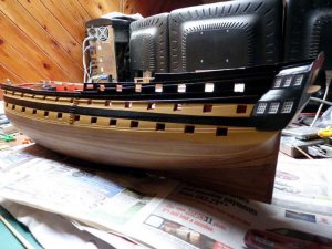
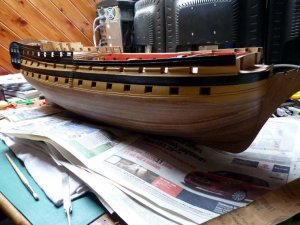
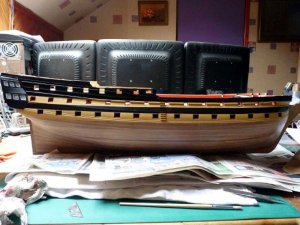
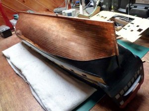
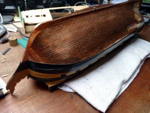
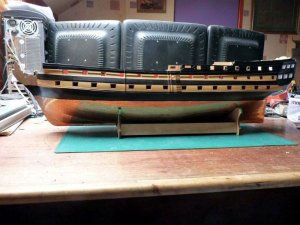
HMS Vanguard 1787 - Victory Models - 1:72 [COMPLETED BUILD]

aew

Administrator
Staff member
Administrator
Joined
Mar 20, 2013
Messages
215
Points
133

Location
Leeds, WY, England
This build log started some time ago - Christmas 2011 in fact, so this is going to start as a catch-up series of posts to bring things up to the present day.
************************************************************


HMS Vanguard 1787

The first POB model ship I built was the French corvette ‘Astrolabe’. I’ve always liked fully rigged ships, but I didn’t want to only build ships of that type so I’ve not built another one since then.
Although Astrolabe turned out to be quite a nice model, the instructions went in the bin at a relatively early stage and it soon became apparent that the historical accuracy of the model was questionable. As I also have a preference for natural wood finishes, I’m equally guilty of not turning out more historically accurate models.

So, I’ve decided to have another go at a fully rigged ship and bought the HMS Vanguard kit by Victory Models (Amati). This time it will be copper plates and paint rather than varnished wood.
There’s no getting away from the fact that this is an expensive kit but it should keep me occupied for at least a couple of years, so that’s my excuse.
There are some excellent build logs on MSW already for this model, so that’s a novelty for me - being able to see what others have achieved with this kit. So far the only modification I’m planning is to fit some LED lighting in various places, but I need to think about that at an early stage.

I’ve had good service from Cornwall Model Boats in the past, so I checked with their website for the kit, I think sometime in early November, only to see it listed as ‘temporarily unavailable’. As I was still finishing Gulnara at that time, that wasn’t a problem.
I checked the website at odd times to see if anything had changed but the expected delivery dates seemed to stay at 2 weeks (assuming that they included Victory Models with Amati). By mid December I was wondering if I could actually get this kit in time for Christmas (contributions towards it as a Christmas present were on offer!) so I queried CMB re the delivery dates using the form on their web page. Somewhat surprisingly, I didn’t receive a response, but the next time I checked the website it no longer showed as out of stock. I did wonder if that was a coincidence or if it had actually been in stock for a while and my enquiry had prompted an update of the page. Anyway, I placed an order.
I ordered it on Friday and received it the following Monday!
The kit is now showing ‘temporarily unavailable’ again.

When I received the order acknowledgement, it included the shipping details showing the kit weighed 14kg. As the saying goes “Never mind the quality, feel the width”. When the kit itself arrived, I took the lid off the box for a quick check, but didn’t open or remove anything, I simply replaced the lid until Christmas.
You may have noticed at this time that I altered my ‘Signature’ to say “Current build: HMS Vanguard – Under the Christmas tree”. That wasn’t actually true – it wouldn’t fit under the Christmas tree!

So, what was in the box and what’s happened so far?
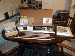
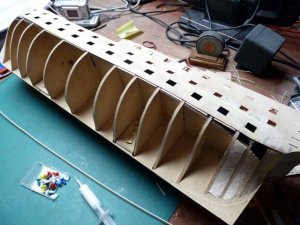
These are general views of the box and its contents.

PICT_V_0101
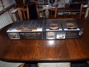
pict_v_0101_.jpg

PICT_V_0102
pict_v_0102_.jpg

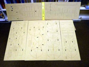
Besides numerous MDF, plywood and hardwood sheets of laser cut parts, there are numerous bundles of what looks to be very good quality strip wood, a bundle of hardwood rods and three fairly large boxes of components.
Finally, there was a large plastic bag containing plans and instructions. I was unimpressed with the instructions that came with Mantua’s Astrolabe kit – until, that is, I bought Amati’s Bireme. They made Astrolabes instructions look positively comprehensive. Krick’s instructions for Gulnara, once I got an English rather than a German set, were passable.
I’d seen posts suggesting that Victory models instructions were fairly good so the contents of the plastic bag were going to be interesting. Lifting them out immediately showed where a reasonable proportion of the 14kg had come from. Out of curiosity I headed for the kitchen scales. We have a vintage set of scales and a set of both metric and imperial weights but I had to resort to the imperial set, I didn’t have enough metric ones! The plans and instructions weighed in at 4lbs 12oz. The calculator gives that as 2.15kg.
A quick check showed that was 20 plans (1x A0 and 19 x A1) and two instruction books.

So that’s what was in the box, what of the progress?
I began by doing what I’d done with Gulnara, I scanned the instructions (the book with the text, not the book of diagrams) and the parts list and stored them as a document and a spreadsheet on the computer. That makes it much easier to check off and identify the various parts. In the course of this I discovered that plans 16 to 20 were full size diagrams of the various wood sheets and brass etchings. (Lots of sheets of brass etchings.)

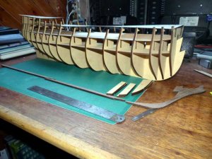
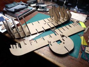
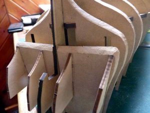
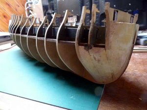
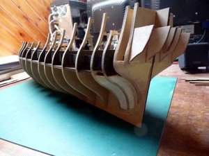
All I’ve done construction wise so far is to dry fit the keel and bulkheads together to see what goes where.

PICT_V_0103
pict_v_0103_.jpg

PICT_V_0104
pict_v_0104_.jpg

I’ve already found a fair few (all be it minor) mistakes though. Hopefully there aren’t any major ones lurking somewhere.
 
Last edited:
Finally, some progress has been made. I’ve had a few days delay sorting out other things. What I thought was a relatively straightforward computer upgrade turned out to be anything but (I shouldn’t have been surprised I suppose) but the main things are working again now

So, what’s happened so far?

The only significant planned departure from a straightforward build is my intention to fit some LED lighting in various places, but that called for some modifications from the very start.
Some time ago Cosmic posted a topic here http://www.modelshipworld.com/phpBB2/viewtopic.php?t=8866&highlight=flicker about making the lights flicker, which I think is very effective. Alexey has fitted lighting in his Vanguard and his log has given me a fair idea of where I need to get to with the wiring. The difference is that I’m not going to fit batteries; I’ll power the lights through the mounting screws in the same way as I powered my bireme.
I’ve been experimenting with a microprocessor I appropriated from my son and I can use that to drive the LEDs. It will drive the LEDs directly and requires no external components other than its power supply. They’re available in different sizes, the one I have has 32 outputs so I think that will be more than adequate for the number of LEDs I’m likely to fit!

Time to do a little machining on the keel.
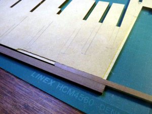
The keel is made from two 5mm thick MDF pieces which are laser cut. (The laser cutting of all the parts is exceptionally good and the use of MDF avoids any problems with warping.) There are 5 laser cut walnut pieces which fit around the MDF sheets. Rather than glue these on at this stage, my intention is to plank the hull before fitting them as I think this will give a neater finish. (Yes, I know I’m going to hide it under copper plates later!)
To get the second planking to fair into the stern post and the keel at the stern, I needed to rebate the keel by 1mm in this area so I used a small router cutter to do this.

PICT_V_0201
pict_v_0201_.jpg

When the bulkheads are in place, I’ll fair them and the keel down to the level of this rebate. Once that’s done, I’ll start a second rebate where this one ends to take the first planking.

The next step was to drill a lot of holes in the keel and bulkheads.

PICT_V_0202
pict_v_0202_.jpg

Most of those in the keel are to thread rubber bands through when I want to hold the planks in place, the ones in the bulkheads are to run the wiring through.

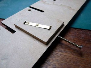
This bit serves two purposes. I’ve drilled the keel for two mounting screws and in order to reinforce it I’ve glued off cuts of MDF on either side at these points. Each screw has a bronze pickup for the electrical connections. I’ll solder wires into these later.

PICT_V_0203
pict_v_0203_.jpg

This next picture is actually the second bit of gluing, I’ve already glued the two walnut pieces together that make up the stem.

PICT_V_0204
pict_v_0204_.jpg

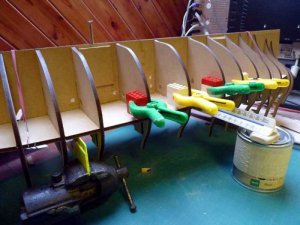
The bulkheads are only glued to the deck at this point, not to the keel. There are lots of glue joints here and it looked as though it could get messy if I tried to do them all at once. Once all the bulkheads are glued to the deck I’ll slide out the keel, glue it and slide it back in.
Lego blocks are very useful for keeping things square!
 
Last edited:
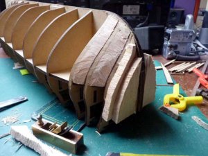
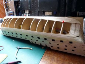
Now that the keel and bulkheads are glued together, I wanted to block out the bow and stern sections. I roughly faired the first few bulkheads and paid the local model shop a visit for some balsa wood. I picked up two thick planks from the oddments bin for £1 each. When I got home, I found that the thicker of the two was an exact fit between the front bulkheads! I used 2 pieces of the thinner block for the bow itself.
This shows the carving in progress:

PICT_V_0301
pict_v_0301_.jpg

The aft bulkhead carries 4 formers for the transom, the bottom part of which is plywood and the first planking ends at this point. I glued these pieces to the bulkhead, dry fitted the bulkhead and roughly faired it to get an idea of how the stern should look.
Note: This bulkhead can’t be glued into place until the plywood strips the carry the lower dummy gun barrels are fitted.
This is the stern bulkhead roughly carved to shape:

PICT_V_0302
pict_v_0302_.jpg

Time to fit the plywood strips so the bulkhead can be glued in place.
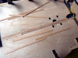
That proved to be an interesting challenge! The strips slide through the stern bulkheads without too much trouble (they curve inboard at both bow and stern) but came to a stop at bulkhead 3. A good soaking seemed to be called for.
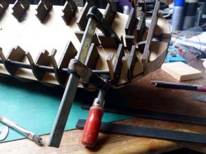
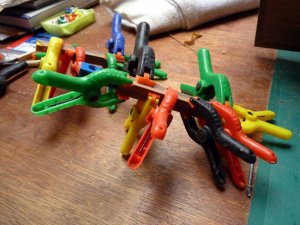
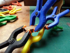
Although that was having some effect, I needed to keep some pressure on the strips to get them to gradually bend inwards. A small G clamp did the job nicely:

PICT_V_0303
pict_v_0303_.jpg

Even when the end was lined up with the slot, the problems weren’t over. Because of the sideways pressure in the bulkheads the strip didn’t want to slide forward. I placed a block of wood in front of the keel where it rises through bulkhead 9 and levered against that to push the strips forward. I then had to repeat the whole procedure to get the strips through bulkhead 2.
The strips are in two separate pieces at each side and I was going to glue an off-cut of plywood behind the joint but I found there was sufficient length to make a short halving joint between the pieces.
I’d painted the strips matt black before fitting them, but I also used some dark wood stain on the false deck and bulkheads. After this, fitting some blocks, gluing the aft bulkhead in place and doing some more carving, this was the result:

PICT_V_0304
pict_v_0304_.jpg

PICT_V_0305
pict_v_0305_.jpg
 
Last edited:
The instructions don’t call for anything further to be fitted on the lower gun deck before the upper gun deck is glued in place. Looking at the instructions though, there are two ladders leading down to this deck. I think these will be virtually invisible once the upper decks and the various ships boats and launches are in place. However, it did seem a suitable spot for a little experimentation.
As I said earlier, I’m intending to install some lighting so a light in this area seemed a good place to start. With a light here, it might just be possible to see the lower gun deck at the foot of these ladders. Even if it isn’t, a trial section of planking here shouldn’t be a problem.
The instructions say “It is not recommended that ‘caulking’ is attempted, as the small scale of the model would make the ‘caulking’ too visible. At this scale (1:72nd), it is highly likely that no caulking would be visible.”
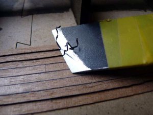
I used black thread to simulate the caulking on Gulnara and was very pleased with the results but in view of the above comments I decided to try an alternative method. I tried the method of inserting strips of thin black paper between the planks. The paper I used came wrapped around a carton of curry from the local fish and chip shop! It was 0.4mm thick and I cut strips off using a guillotine and coloured it with a black marker pen.
The first attempts were only moderately successful; it was fiddly to get the strips into position and sections of the paper tended to pull out later when the excess was trimmed off. Later attempts, moistening the deck and planks before applying the glue and running a wet brush along the paper strip once the plank was positioned, were much more successful.
This shows the strips in position and being trimmed flush:

PICT_V_0401
pict_v_0401_.jpg

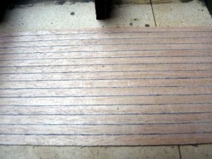
This is what the planking looked like after scraping it smooth:

PICT_V_0402
pict_v_0402_.jpg

Comparing this with the caulking on Gulnara (1:50 scale) -

Gulnara
gulnara.jpg

- I couldn’t see too much difference between them despite the fact that I used 0.14mm diameter thread on Gulnara which should make the seams over three times the width.
The paper was significantly more difficult to use than the thread so I think I’ll use thread for the rest of the caulking. I have some 0.1 mm thread which should give seams equivalent to 7.2mm full size. That seems quite reasonable and even the 0.14mm thread (11mm full size) doesn’t sound as though it would have been excessive.

The next step was to try a light above this piece of the deck:

PICT_V_0403
pict_v_0403_.jpg


The LED is fitted in the deck beam, midway between the two hatches.
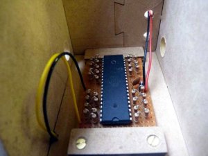
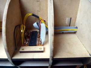
And this is what’s driving the LED:

PICT_V_0404
pict_v_0404_.jpg

I said earlier that I could drive the LEDs directly from the chip; whilst that’s true, it supplies too much current so I’ve added resistors to limit the current to 20mA per LED. There are 32 separate outputs available, that should be plenty!
The next picture shows it after a bit of work with the soldering iron:

PICT_V_0405
pict_v_0405_.jpg

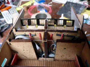
The ribbon cable runs all the way to the stern and the yellow wires with it drop off along the way to light the poop deck area. There are also wires running left to the fore deck area.

Having now glued the upper gun deck pattern in place, as per the instructions, I now see I’ve made my first mistake!
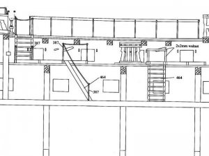
Plan No.4 includes a cut-away view of the hull. This shows the stairways referred to earlier:

PICT_V_0406
pict_v_0406_.jpg

The aft ladder has hand ropes and stanchions, the lower pair of which fit in the lower gun deck. I can no longer get directly above these to drill mounting holes to fit them! With a bit of careful measuring, hopefully, I should be able to drill these from underneath.
 
Last edited:
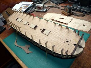
Next job was to fit the gun deck. This is supplied as two separate plywood sheets, one for the forward 2/3rds of the deck and the other for the aft section. Fitting these is quite a challenge, they need to be rolled/folded along their length a considerable amount to get them between the frames. The instructions suggest either fitting them and then planking them in situ or, alternatively, cutting them in half (lengthways), planking the halves, and then fitting them. I compromised; I cut them in half, fitted them, and then planked them!

The instructions imply that the whole of this deck is to be planked but I suspect that a large part of it will not be visible when the upper decks are added. I’m doing as I’m told; I suppose at least I’ll be able to show pictures of that deck later.
The instructions suggest a 4 plank stagger. Assuming 20 foot planks, that equates to just under 85mm at 1:72 scale, so 84mm planks is a nice length to keep the measurements simple.
As mentioned earlier, the instructions suggest caulking wouldn’t be visible at this scale, but this time I’m going to ignore them.
After my experiment with black paper, I’m going to revert to the method I used on Gulnara, namely 0.1mm black thread. That scales up to 7.2mm seams between the planks which doesn’t sound unreasonable to me.
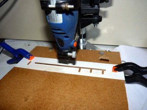
I set up the guillotine to 84mm and sliced up a couple of strips of the 3mm x 1mm tanganyika. I decided to drill the various nail holes in the planks, but not to make any attempt to fill them, I think they should just be visible. I made up a simple jig by taping a length of card on the drill table and gluing strips of wood to it, one long length to lay the plank along and four short ‘stops’ for the hole locations. The left hand stop is for the end holes and the three right hand ones do the intermediate holes.

PICT_V_0501
pict_v_0501_.jpg

It was just a matter of moving the planks along and turning them round to drill the various holes.
This picture shows some of the drilled planks and also the first ones glued in position:

PICT_V_0502
pict_v_0502_.jpg

I planked the sections between the hatches with full length planks but left the final section from the aft most hatch to the rear bulkhead until later. That way, when I laid the first uninterrupted length of planking, outboard of the hatches, I was able to match the butt positions. At this point I found, purely by chance, that with an 84mm plank length (plus caulking) the deck was exactly 8 planks long. (I had to update the spreadsheet I use for the plank layout as it couldn’t cope with a deck that long!)

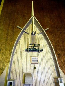
After a few days cutting, drilling, gluing and, finally, scraping, this was the result:

PICT_V_0503
pict_v_0503_.jpg

I’ll varnish it later when the deck fittings are sorted.
 
Last edited:
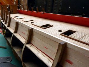
The next step was to plank the inside of the bulwarks of the upper gun deck. This instruction comes with a warning to do it carefully as it’s difficult to sand it afterwards. I decided to experiment and sand and paint the inner surfaces of the planks before fitting them. I figured that if it didn’t work, I could still sand them and paint them afterwards. I’m quite satisfied with the results.

PICT_V_0601
pict_v_0601_.jpg

Now for a little progress on the deck fittings.

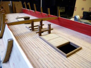
The main bitts are provided as laser cut walnut parts. The forward pair fit through the upper gun deck and locate in holes in the lower gun deck. The aft ones fit in a similar way but extend all the way up to locate in notches in the beam supporting the main deck. As mentioned in an earlier post, the holes I’d cut in the deck planking were slightly too large for the bitts so I framed them with off cuts of the planking.
The instructions don’t say anything about shaping the bitts but I opted to carve the tops and ends before assembling them.

PICT_V_0602
pict_v_0602_.jpg

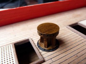
The next items were the capstans. These are assembled from various plywood parts fitted around a length of 10mm dowel. These turned out to be an interesting little challenge! The tops are no problem, just a matter of gluing some plywood discs together. I next cut off a 22mm length of dowel as per the instructions and glued that into the assembled plywood pieces. Although that works, there was a problem and I changed the method for the second one and simply glued the plywood pieces onto the full length piece of dowel. All will be revealed shortly.
The challenge was what to do with the whelps. There are 20 of these supplied, 10 per capstan. The picture in the instruction book shows them spaced evenly but I opted to glue them together in pairs to make 5 thicker whelps per capstan. Whether I fitted 10 thin or 5 thick whelps, the challenge remained, getting them evenly spaced. I finally glued one in, then made an inspired guess at the correct spacing and shaped the end of a piece of plank to fit in the gap between them. I used the wedge to work around the capstan and when I got to the last space, if the gap was too small I shaved a bit of the side of the wedge and went round again. If the gap was too large I shaved a bit off the end of the wedge instead.
Once the capstan was glued together, the problem mentioned earlier became obvious. The capstans fit in holes cut in the plywood deck. However, in both cases the MDF keel runs across the bottom of the hole. That means that only about 2mm of dowel should be protruding from the base of the capstan. OK, at least it’s too long rather than too short but holding the capstan to saw off the excess isn’t easy. With the second one having the full length of dowel, it was just a case of holding the dowel in the vice and sawing the capstan off the end.
What were missing were the pawls to stop the capstan running backwards.
I cut some discs of card to fit under each capstan. I then made a ring from 0.5mm brass wire just larger than the capstan base, soldered the ends together and glued it to the card. I cut several short pieces off a 1mm square wood strip and glued these to the card just inside the wire to represent the stops and painted it all matt black.
I made the pawls from short lengths of 0.5mm brass wire by simply forming a loop at one end. They were fitted to the base of the capstan with 0.7mm copper nails.

PICT_V_0603
pict_v_0603_.jpg

Time to have a look at the ships stove.
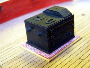
The basic structure is made from plywood and this is then fitted with photo etched panels and fittings. The plywood pieces fit together very well, although I did find that the two holes in the end panel didn’t line up with those in the etching. Nothing that a 2mm drill couldn’t sort out.
I soldered the little lids and doors to the panels. These are supposed to have handles made from 0.7mm brass wire but, checking the parts list, the only wire supplied is 1mm. I have some 0.5mm and 0.8mm wire but not 0.7mm wire. After a bit of searching I found some 0.7mm copper wire so the stove now has copper handles.
The grid for the rotisserie at the rear of the stove is supposed to be made from 1mm wire but that seemed to be much too large. Checking the holes in the sides, they seemed to be just under 0.5mm so I ran a 0.5mm drill through them and used 0.5mm wire. I soldered the wires in place and also soldered front and side panels together. I then slid the assembly off of the top, applied some glue and slid it back on. The top plate was assembled the same way. I tried blackening the brass, but wasn’t happy with the result. As part of the stove had to be painted anyway, I painted the brass as well.
Although not mentioned on the assembly instructions, the side panels actually have holes for the lifting rings and also for side rails to hang the various fire irons from.
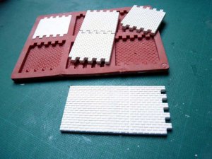
I’ve seen other models with the stove sitting on a brick platform. Many years ago I had a set of moulds to cast parts for model buildings. These were called Linka System - http://www.linkaworld.com/ - and were made to match 00 gauge model railways. Just the right scale!
After a little bit of searching and some mixing, I had half a dozen brick walls:

PICT_V_0604
pict_v_0604_.jpg

I only needed two pieces and only the edges of those will actually be seen. After painting the panel, I glued it to the deck and made a wooden frame to fit around the brick plinth.
This is how the stove looks in position:

PICT_V_0605
pict_v_0605_.jpg

To work out the correct position for the stove, it was necessary to dry fit the upper deck and centre the chimney under the appropriate cut out. With that deck in place, the stove is virtually invisible!

I obviously need to take plenty of photographs before I finally fit that deck!
 
Last edited:
Upper gun deck lights.

I’ve reached the stage where I can fit the deck beams for the upper deck. The plan was to install lights under this deck around the open area where the ships boats are stored.
I’d already experimented with fitting an LED on the lower gun deck and this is the method I used:
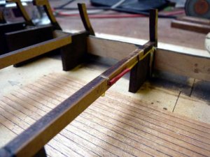
I drilled two holes through the deck beam (aligned fore and aft) at the correct spacing to fit the LED. I then made a shallow saw cut across the top of the beam, running through the holes. I put a ‘+’ mark in pencil on one side of the beam and then fitted the LED with the long lead to the ‘+’ side. I then bent the leads outward in the saw cut.

PICT_V_0701
pict_v_0701_.jpg

The leads were later bent to run alongside the beam towards the supply and return wires. The supply wires I installed earlier run up alongside the frame extensions that support these beams.
I earlier ran a length of wire along the top of the support strip for the dummy barrels which forms the common negative for all the LEDs so it was simply a case of soldering a length of black wire to this to act as the return wire and running it up the other side of the frame from the supply wires.
With some heat shrink sleeving in position, this is how it looked:

PICT_V_0702
pict_v_0702_.jpg

And after applying a little hot air and gluing the beam in position, this was the result:

PICT_V_0703
pict_v_0703_.jpg

When the deck is in place, the beam itself won’t be visible, although the LEDs themselves may be. At the bow, my intention is to leave the beak-head doors open so it may be possible to see the first beam (2a) through them. For that reason I didn’t run wires along the front of that beam. Instead I ran the leads forward to the first bulkhead and then down through the deck at the side of the bowsprit. I also painted the front of that beam red to match the bulwarks.
These are the LEDs at the forward end:

PICT_V_0704
pict_v_0704_.jpg
 
Last edited:
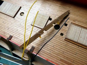
Yet more lights.

The next step in the instructions is to fit the plywood gun port patterns. However, before I fitted these, I had to make sure that the wiring for the rest of the lighting was accessible.
I needed to bring up the negative leads for the lights on the upper deck and also for those at the stern. Those for the upper deck lighting were soldered to the negative wire previously installed over the dummy gun barrel strip and from there were run with the yellow supply wires I’d also fitted earlier.
At the stern, I’d coiled the end of this negative wire to sort out later. I decided to bring it to the top of the bulkheads where it will be easily accessible.

PICT_V_0801
pict_v_0801_.jpg

This seemed to be a good time to fit the LEDs in the lower section of the stern galleries. I’m not sure how much of the interior of these will be visible so I gave them a preliminary coat of white paint for the moment. With a little bit of judicious bending, the LEDs leads were then fitted through the stern bulkhead.

PICT_V_0802
pict_v_0802_.jpg

Connecting them up was just a case of a little more soldering and some sleeving.

PICT_V_0803
pict_v_0803_.jpg
 
Last edited:
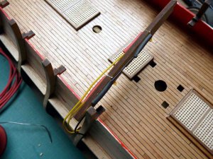
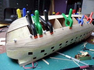
Next stage was to fit the plywood gun port patterns. The first step was to trim the edges of the lower gun deck wherever it protruded past the bulkheads. The instructions say to leave the sheets soaking in water for at least 20 minutes. Being a little suspicious of the various qualities of plywood, I soaked just one sheet, the upper, aft port side piece. (there are four pieces per side.) I needn’t have worried, the plywood seemed to be very good quality and showed no sign of delaminating. Deciding exactly where it should fit, mainly fore and aft was a little bit of an exercise but I decided that the vertical joints between the sheets should lie on the bulkhead centres. I held the sheet in place with numerous clips and rubber bands and left it to dry whilst I soaked the forward section.
Gluing these two pieces into place wasn’t too much of a problem, the only problem area was at the bottom corners at the stern. Just at the corners, these pieces curve under the stern. I found it necessary to score the outer layer of the ply wood just at these points.

PICT_V_0901
pict_v_0901_.jpg

The next two pieces were more of a challenge, particularly the forward ones. Both these are curved, vertically, to follow the hull profile ad the forward pieces curve horizontally around the bow. In addition, they also have a very pronounced outward curve at the top forward corner. To curve the aft pieces, I bound them to a length of plastic waste pipe until they dried:

PICT_V_0902
pict_v_0902_.jpg

It was at this stage that I realised that I was faced with different problems on the two sides. The plywood pieces I was using for the port side had the grain of the outer layers of the plywood running fore and aft whereas those on the starboard side had the grain running vertically. When I unbound the two pieces, the port side was actually curved too much (easily rectified) but the starboard piece tended to straighten out.
When I tried the pieces in position, the pieces didn’t line up very well with the upper section (in terms of the surfaces being level). As a way of resolving this, I glued short strips of wood under the edges of the plywood to hold the edge straight. These then supported the edge of the adjacent sheet. On the port side the strips were initially glued to the upper section:

PICT_V_0903
pict_v_0903_.jpg

On the starboard side, I glued the strips to the sheet I was attaching:

PICT_V_0904
pict_v_0904_.jpg

These two lower forward panels wrap around the bow. That for the port side, with the grain running fore and aft, definitely did not want to bend that way! The starboard panel bent very easily.
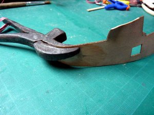
Some time ago, I was given an old, curiously shaped, pair of pliers. At the time, I’d no idea what they were for but I later found they were for stretching leather or other material in upholstery work. They’ve since found a new life bending planks and plywood:

PICT_V_0905
pict_v_0905_.jpg

The strips of wood did a pretty good job of keeping the edges of the plywood panels straight and level so I continued the practice along the bottom edge where they will meet the first planking:

PICT_V_0906
pict_v_0906_.jpg

I also, as I’ve seen in other logs, added spacers between the top of the bulwark planking and the plywood sides to keep things straight there as well.
 
Last edited:
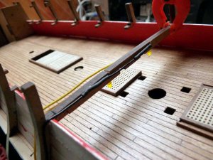
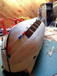
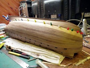
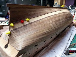
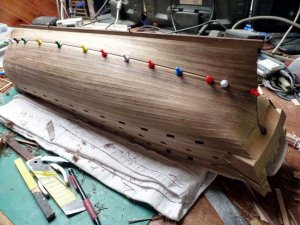
Time to make a start on planking the rest of the hull.
The first few planks from the keel didn’t require any shaping but they were faired into the rebates I’d cut earlier into the keel at the stern. The planks adjacent to the gun port patterns needed to be tapered at the bow.

PICT_V_1001
pict_v_1001_.jpg

After trying a few test planks in between those already fitted, I opted to work ‘up’ towards the keel. Things were a bit crowded at the bow so a couple of planks were dropped to make things fit.

PICT_V_1002
pict_v_1002_.jpg

With a little bit of adjustment to the plank widths along their lengths, things were looking respectable.

PICT_V_1003
pict_v_1003_.jpg

Yes, this gap is less than the plank widths!

PICT_V_1004
pict_v_1004_.jpg

There, that proves it!

PICT_V_1005
pict_v_1005_.jpg

Time to move outdoors and get out the scrapers to clean things up.

PICT_V_1006
pict_v_1006_.jpg

Work was temporarily interrupted when my daughter and granddaughter came visiting and took over the table for lunch, but this was the eventual result:

PICT_V_1007
pict_v_1007_.jpg

I have since done one further job; I glued the stand together. I’d forgotten what the ship looked like the right way up!

Time to read the instructions and see what I’m supposed to do next.
 
Last edited:
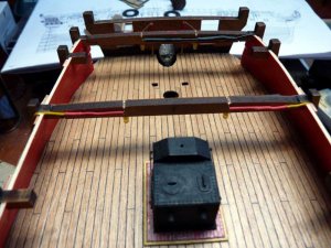
Before I start the second planking I’m supposed to fit the ‘basic side gallery pattern assemblies’, however there is a note suggesting leaving off the window frames whilst doing the second planking.

There are several plywood pieces with tabs that fit in slots in the hull. These form the basic frames for the galleries, but other pieces then fit above and below these, bread and butter style, to make thicker pieces. These pieces fit at an angle and it’s a case of temporarily fitting the stern fascia (very fiddly!) and using that to judge the appropriate angles. Just to complicate matters further, I needed to fit lights in two of these pieces on each side.
I started by gluing in the three tabbed pieces on each side that didn’t need lights which at least gave me a guide to how things fitted. The next job was to fit LEDs in the other tabbed pieces. With the two lower galleries, they extended just far enough forward that I could drill through the hull to the space where I’d run the wiring to, so all I needed to do was get the LED leads to the front of the plywood piece. I carved a slot in the top of the lower plywood piece for one lead and a similar slot in the top of the middle, tabbed piece for the other lead.

PICT_V_1101
pict_v_1101_.jpg

With a little judicious bending, the leads came out at the right place:

PICT_V_1102
pict_v_1102_.jpg

I just needed to note which lead was which and bevel the edges of the pieces. (The dirty looking plywood is the result of sanding the burnt edges resulting from the laser cutting).
Next job was to glue up the sandwich:

PICT_V_1103
pict_v_1103_.jpg

And finally connect things up:

PICT_V_1104
pict_v_1104_.jpg

The top gallery was a little more difficult, it’s made up of only two pieces of plywood and doesn’t extend far enough forward to connect things in the same way. In this case, I managed to cut two grooves in the same piece of plywood without the dividing strip breaking away:

PICT_V_1105
pict_v_1105_.jpg

Unfortunately, the wires have to run through the top corner of the stern gallery:

PICT_V_1106
pict_v_1106_.jpg

I think some white paint would probably suffice, but I can always resort to filler.
Maybe the captain would like to hang some pictures on that corner wall?

In order to get the gallery patterns in the correct places, I temporarily fitted the window frames and also glued in the panels between them. Most of these pieces came from a sheet of 1.5mm walnut ply which was the only poor quality item I’ve found:

PICT_V_1107
pict_v_1107_.jpg

Fortunately, only the one window frame was seriously affected and I was able to glue the laminations back together.
 
Last edited:
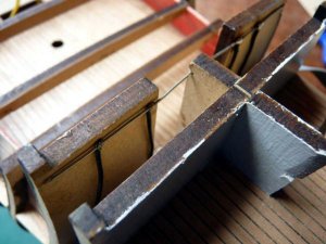
So, on with the second planking.

The instructions offer two alternative methods; to mark out the position of the main wale and work from that or to start from the top of the gunport patterns. As the planks in this area will be painted, working from the top of the gunport patterns seemed the easier option.
To get the first plank level with the gunports, I made a highly technical jig. I cut a scrap of the first planking to match the height of the gunports and glued it to a longer piece butted up against the underside of the first plank.

PICT_V_1201
pict_v_1201_.jpg

After making a few more the same, I could glue the plank in place at a consistent spacing from the ports:

PICT_V_1202
pict_v_1202_.jpg

The next few planks were all full width and, for the most part, parallel. I fitted a short stealer between the first and second planks at the forward end to allow me to form the arched section below them with the following planks.

PICT_V_1203
pict_v_1203_.jpg

At this point, I hadn’t fitted any of the walnut pieces that make up the keel. Leaving off the stem and stern posts makes it much easier to fit the planks, although it will require a bit of careful carving later to get them in place. Without the stem in place, I could clamp the plank ends firmly in place whilst the glue set:

PICT_V_1204
pict_v_1204_.jpg

Once the glue had set, it was relatively easy to trim those plank ends to allow me to dry fit the stem, although planks nearer the keel, which join at a much shallower angle, will be more of a challenge. With the stem in place, I was able to see how the walnut keel pieces and the garboard plank came together.
These were then glued in place:

PICT_V_1205
pict_v_1205_.jpg

It’s now just a case of filling the gap with planks!

PICT_V_1206
pict_v_1206_.jpg

It does, however, require some dropped planks and stealers to keep things even:

PICT_V_1207
pict_v_1207_.jpg

You can see in the picture above how leaving off the stern post makes the planking much easier at the stern.

The end is in sight, the remaining gap is just under 5mm wide.

PICT_V_1208
pict_v_1208_.jpg

Believe it or not, I failed to take a photograph after I’d fitted the last planks!
Just to prove the last plank did fit, here’s a picture I took whilst I was cleaning up the stern in preparation for fitting the stern post:

PICT_V_1209
pict_v_1209_.jpg

More pictures once I’ve cleaned things up.
 
Last edited:
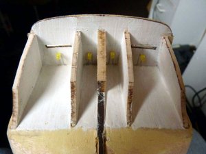
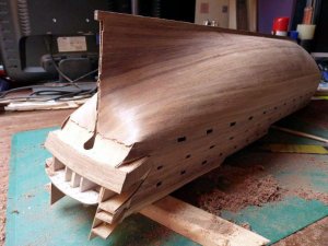
Next job was to clean up the planking and fit the stem and sternpost.

The top part of the stem fits in a slot so it’s easy to hold it against the upper rows of plank ends. Having done that I scored across the ends of these planks on either side of the stem. I was then able to remove it an cut the scored planks to length. When the stem was re-fitted, it slotted between those planks and allowed me to score the next few planks; and so on….
A little bit of care was required as I approached the keel, both to keep the stem in line with the keel and because the planks here join at a much shallower angle.
This was how it looked at this point:

PICT_V_1301
pict_v_1301_.jpg

The stem was finally glued into place:

PICT_V_1302
pict_v_1302_.jpg

The stern post was comparatively simple to fit. Most of the planks were simply cut off flush with the MDF keel. Only a few approaching the transom needed scoring and cutting in the same way as those at the bow:

PICT_V_1303
pict_v_1303_.jpg

This shows the stern post in place:

PICT_V_1304
pict_v_1304_.jpg

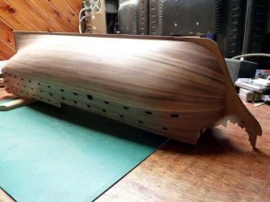
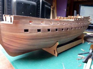
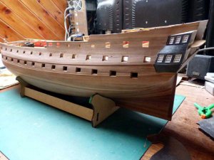
This is how the hull looks now:

PICT_V_1305
pict_v_1305_.jpg

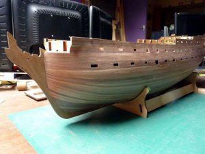
I’d almost forgotten what it looked like the right way up:

PICT_V_1306
pict_v_1306_.jpg

Next job is to sort out the gunports.
 
Last edited:
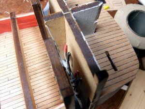
Framing the gunports raised a few problems.
I’d seen some posts showing how to do this by building some square tubes of the appropriate size and cutting off sections to make the individual frames. The ports on the upper gun deck are 12mm x 10mm so 4 pairs of 5mm x 1mm planks glued edge to edge is exactly the right size. With some Lego blocks to keep things square, I glued two horizontal pairs to two vertical pairs:

PICT_V_1401
pict_v_1401_.jpg

Then glued the resulting corner sections together:

PICT_V_1402
pict_v_1402_.jpg

PICT_V_1403
pict_v_1403_.jpg

I cleaned up the second planking around each gunport on the upper gun deck (those on the lower gun deck are larger) until the tube fitted through the port. Once that was done I cut a corresponding hole through the bulwarks so that the tube fitted through that also.
The ports that don’t have lids are framed flush with the outer hull so I decided to start with those as they were going to be easier to do! I first scribed round the inboard end of the tube and cut off the excess so that it matched the profile of the bulkhead. Once I’d cleaned that end up, I refitted the tube and drew around the outer end with a pencil. Cutting off the piece at the pencil line gave me just a little bit to spare.
I put glue on the inner bulkhead and the outer edge of the frame:

PICT_V_1404
pict_v_1404_.jpg

This picture shows the tube in the port, one frame ready to be cleaned up and one port framed:

PICT_V_1405
pict_v_1405_.jpg

After a bit of practice, I got brave enough to try framing the ports that have lids. I pulled the tubes back 1mm before marking where to cut them and rather than marking them with a pencil, I scribed around them with the knife point. This way, I could cut them very close to the exact length. Once I’d cut them off I refitted them again recessed 1mm at the inboard end, and checked where they needed to be trimmed/sanded to length. Gluing them in flush with the bulwarks then gave the requisite 1mm rebate at the outboard end.

At this point, I was at a loss how to frame the lower gun deck ports! I remember seeing something about this, but I don’t recall it showing the method used and I failed to find the post.
I considered using the same technique as for the upper gun deck ports but I could see that, inevitably, I would end up pushing the frame completely through the port at which point I would be unable to retrieve it.
Alternatively, I considered pushing the tube all the way in until it butted up against the ply strip that holds the dummy barrels. Although that would mean I couldn’t lose it inside, I didn’t think the frames would look right. They would be much too deep.
This is the kit of parts I settled on:

PICT_V_1406
pict_v_1406_.jpg

I’d actually fitted the lower parts of a few frames by the time I took this photograph, but all will be revealed!
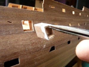
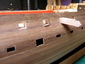
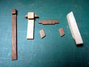
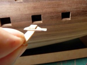
The strip for the top or bottom of the frame is notched at each end to allow for the thickness of the plywood patterns. It slots into the special tool (patent not yet applied for) which allows it to be hooked through the port and manoeuvred into position:

PICT_V_1407
pict_v_1407_.jpg

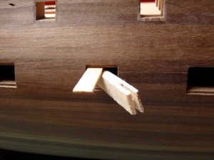
Special tool No.2 holds it in place:

PICT_V_1408
pict_v_1408_.jpg

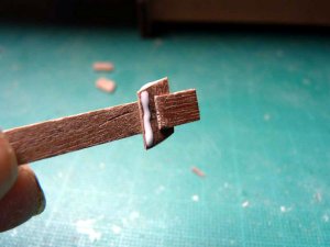
This is special tool No.3:

PICT_V_1409
pict_v_1409_.jpg

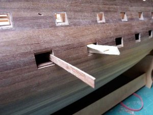
There are subtle differences between tools Nos. 1 and 3, developed as a result of the first version falling out! The strip of wood (off-cut of first planking) used to form the body of the first tool was progressively cut shorter until it balanced. This made it much easier to get the lower piece of the frame level. Tool No. 3 is just the opposite, the weight of it holds the side pieces in place.

PICT_V_1410
pict_v_1410_.jpg

This picture shows progress so far:

PICT_V_1411
pict_v_1411_.jpg

All the ports on the upper gun deck are framed, both port and starboard.
 
Last edited:
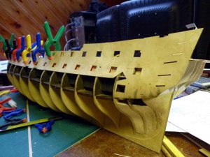
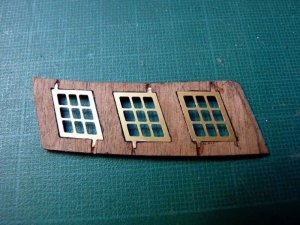
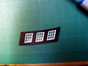
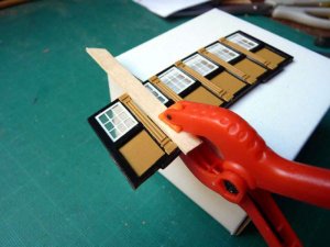
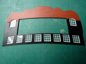
With the gunports on both the lower and upper decks framed I looked at the next stage in the construction of the stern galleries. The window frames are photo etchings which have to be fitted in the walnut ply panels. The plywood pieces are to be painted black and the photo etchings white. I painted all the white pieces on the sheet holding the window frames at the same time.
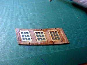
When I cut out the first photo etched window frame, I was a little surprised to find it was an exact fit inside the hole in the plywood frame. I hadn’t really given any thought to how it would actually be held in place. Fortunately I hadn’t trimmed off the tabs at the edges of the frame at that time. I was able to make small notches in the plywood to accommodate these and a drop of superglue on each held the frames in place:

PICT_V_1501
pict_v_1501_.jpg

The instructions recommend glazing the windows, which I intended to do anyway, but seemed to show individual panels behind each frame. Instead, I opted to fit the frames flush with the back of the plywood and use a single piece of acetate across the back of all three frames:

PICT_V_1502
pict_v_1502_.jpg

When I held the assembly up to the light, daylight was visible around the edges of the frames. Normally, this wouldn’t be an issue, but because I had fitted lighting in these galleries this wouldn’t look right with the lights on. I later painted a black border around each window on the back of the acetate.
This is how the frame looked at this stage:

PICT_V_1503
pict_v_1503_.jpg

Note that very little of the black area will be visible once the decorative parts are fitted later.

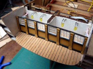
I glazed the stern screen bulkhead in a similar manner, but in this case I could also fit the decorative columns:

PICT_V_1504
pict_v_1504_.jpg

Next step was to plank the wales. The instructions say to mark out the positions from the elevation drawing, but this led to some confusion. The main wale is made up from two 4mm x 1mm strips and two 5mm x 1mm strips, a total of 18mm. There is also a 3mm x 0.5mm strip (strake) at the top making a grand total of 21mm.
The elevation should show three lines but only shows two, 18mm apart rather than 21mm. As this is the total width of the 1mm thick planks, I assumed that the strake was not shown and marked out the position on that basis.
This is how the main wale looks:

PICT_V_1505
pict_v_1505_.jpg

This is how it looks with both wales planked:
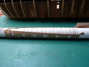
PICT_V_1506
pict_v_1506_.jpg

With the benefit of hindsight, I think it would have been easier had I left the framing of the three stern gunports on both gun decks until after the wales were planked. Cutting the wales to align with the frames needed some care.

The picture above also shows the stern galleries and their window frames. At the moment, the upper wale runs on to the window frame. To fit the decorative pieces, I think it will have to be cut short at this point.
Any pictures anyone?
 
Last edited:
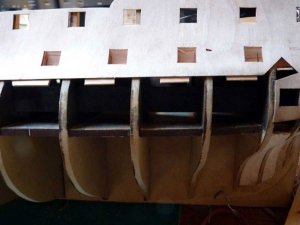
The next step seemed to be to continue with the stern galleries. That required some more work on the stern including fitting the screen bulkhead and the stern fascia.
Before fitting these I needed to fit some more lights. I’d only intended to fit two lights in the upper galleries, but as I had some spare circuits I decided to fit two in each side:
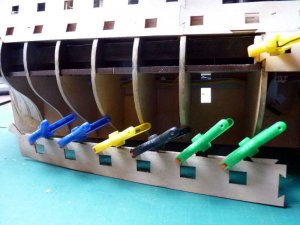
PICT_V_1601
pict_v_1601_.jpg

This is how it looked with the screen bulkhead fitted:

PICT_V_1602
pict_v_1602_.jpg

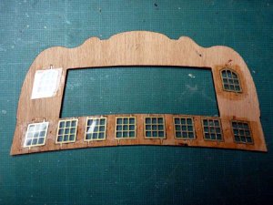
I fitted the window frames in the stern fascia in the same way as those in the galleries:

PICT_V_1603
pict_v_1603_.jpg

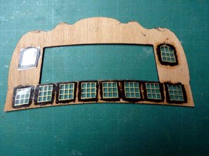
This is the step I didn’t show previously. Painting the acetate sheet black around the windows stops light shining through at the edges of the frames:

PICT_V_1604
pict_v_1604_.jpg

The next picture shows how the fascia looked at this time. Practically the whole of this will be covered with decorative pieces. The top section is painted red as this is the required background colour for the decorations in this area.

PICT_V_1605
pict_v_1605_.jpg

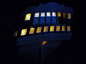
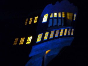
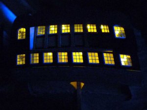
The next pictures are provided in response to popular request. Honest, they do flicker!
Unfortunately, although I didn’t notice most of them at this point, looking at the pictures afterwards, a few problems ‘came to light’. :)

PICT_V_1606
pict_v_1606_.jpg

PICT_V_1607
pict_v_1607_.jpg

PICT_V_1608
pict_v_1608_.jpg

There are one or two places where light is showing through; along the bottom edge of the fascia and just under the starboard side of the balcony, but most noticeably in the hole for the rudder post.
I still had the final planking to do on the transom which would eliminate one area and a spot of glue, filler and touch up paint would seal the joint under the balcony, but the rudder hole was more of a challenge.
Using a pair of tweezers, I was able to insert a couple of short planks at the bottom (top?) of this hole to form a floor for the lower centre galleries. Once that was done, I made a cardboard tube to ‘frame’ the hole just like framing the gunports, and glued it in place. When the glue had set, I trimmed the cardboard off flush with the plywood and planked the transom.
This is how it looked:

PICT_V_1609
pict_v_1609_.jpg

I’ll paint the card black at a later stage.

This is how the stern looks now:

PICT_V_1610
pict_v_1610_.jpg
 
Last edited:
Just to prove (not that proof is really needed!) that things don’t always go according to plan; here are a couple of items that needed rectification.

One of the first things that are supposed to be assembled and fitted to the hull is the upper gundeck front platform together with the beakhead bulkhead which sits above it. I opted to plank this piece of deck at the same time as the rest of the gundeck:

PICT_V_1701
pict_v_1701_.jpg

At about the same time, I had to assemble and fit the main bitts. The aft ones extend up to meet a deck beam but as there was no such beam above the forward bitts, I opted to carve these to shape:

PICT_V_1702
pict_v_1702_.jpg

So, what went wrong?
Yes, I did read ahead, but I didn’t cut out the later parts and test fit them! The first problem came to light after I’d planked the channel wales and test fitted the bow grating:

PICT_V_1703
pict_v_1703_.jpg

Fortunately, although I’d assembled the bulkhead, I hadn’t glued it in place so re-planking the platform wasn’t too much of a problem.
Things now fit as they should:

PICT_V_1704
pict_v_1704_.jpg

The piece of planking is just to keep the front of the grating straight.

Next job was to undo my carving on the main bitts:

PICT_V_1705
pict_v_1705_.jpg

The need for that wasn’t quite so easy to foresee. There is a large well in the upper deck and a number of beams fit across the open area to support the ships boats.
Yes you can probably see what’s coming; measuring out where each of these goes, followed by a test fit, showed that the aft most of these sits across the top of the bitts!

PICT_V_1706
pict_v_1706_.jpg

Was Murphy a shipwright? :)
 
Last edited:
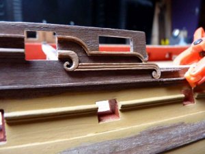
There are various profiled walnut strips provided for mouldings along the ship’s hull, together with some plywood decorative pieces. One of the plywood pieces forms the end of the upper two mouldings, an ‘L’ section piece and a bull-nosed section. The flat plywood section didn’t match the mouldings so I elected to try a little carving. I expected the plywood to break up and that I would have to remake the piece but it didn’t.
This was the result:

PICT_V_1801
pict_v_1801_.jpg

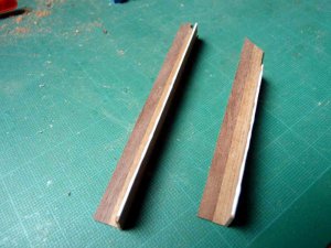
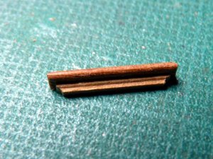
The steps on the hull side are supposed to be made by gluing a length of 1 x 1mm strip on to a length of 2 x 1mm strip to form an ‘L’ section. As that’s just the same as the pieces provided for the mouldings, I couldn’t really understand why these were to be made of a built up section. As there are 13 steps per side and each is supposed to be 26mm long, I assumed I wouldn’t have enough of the ‘L’ shaped strips to use those, so I did as I was told and glued the strips together:

PICT_V_1802
pict_v_1802_.jpg

I ground out the required profile, a rounded edge to the 2 x 1mm step and a small rebate in the 1 x 1mm support piece, in an old Stanley knife blade to shape the strip. Having shaped the strip, I cut off 26mm and tried it for size. It was far too long! I opened up plan 1, which is full scale size, and measured the length from that. The steps should actually be 13mm long so it’s quite possible that I could have made them using the walnut sections supplied.
Anyway, this is how they looked:

PICT_V_1803
pict_v_1803_.jpg

I’d already painted two yellow ochre bands along the lower two rows of gunports so I crossed my fingers and applied some masking tape to mark out the upper two black bands.
This is it at the moment of truth, just before peeling off the tape:

PICT_V_1804
pict_v_1804_.jpg

There were actually surprisingly few places that needed attention. Most of those were simply cleaned up with either light scraping with a knife point or a glass fibre pen:

PICT_V_1805-7
pict_v_1805_.jpg

pict_v_1806_.jpg

pict_v_1807_.jpg

Next step is to mark out the waterline, mask the area between that and the lower gunports and paint that area black also.
 
Last edited:
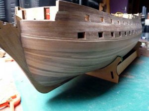
Just a minor update this time.

I marked out the water line and followed Mitsuaki’s technique of gluing a 1mm square strip along the hull to form the boundary for the copper sheathing.
I tried using a laser level to mark the water line, but while it worked just fine for showing where it should be, it wasn’t quite so easy to mark the hull at that point. I was forever interrupting the beam with my hand.
I have a surface gauge (and a surface plate – but that’s going to extremes!) but I found it easier to just cut a strip of wood to a length equal to the height of the water line above the bench and use that to make numerous small scribe marks on the hull.
I ‘joined the dots’ with a line of masking tape and then glued the 1mm strip alongside the tape.
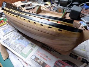
This is how the hull looks after also masking below the gunports and painting the intervening area:

PICT_V_1901
pict_v_1901_.jpg
 
Last edited:
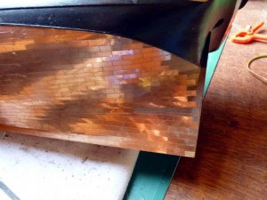
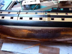
It’s been a while since the last update, but a lot of new parts have been added. However, I’m afraid the variety is limited, they’re all copper plates.

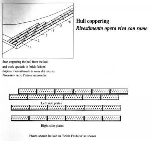
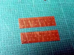
The plates are supplied in sheets, seven plates wide and a whole row can be broken off and attached, or the row can be further broken into individual plates. Unlike copper tape, because of the thickness of these, they can’t be overlapped and have to be laid edge to edge. The plates have simulated nails imprinted in them with one long edge and one short edge having continuous rows along them. Two different patterns are supplied.
This is what the instructions say:

PICT_V_2001
pict_v_2001_.jpg

If the plates were actually laid this way, I think the pictures of the left and right sides are transposed. I hope that’s the case, because I’ve laid my plates the opposite way!
The instructions say to use thick superglue (CA) to attach the plates but I’m not a fan of that and I’d be sure to end up with more of it on the front than the back of the plates. Instead, I used some ‘adjustable’ contact adhesive. In practice, it could be used like ordinary adhesive, i.e. just apply it to the copper plates and stick them in place immediately. Any excess could be removed some time later with white spirit.

Because the plates can’t actually be overlapped, stealers are quite a challenge; they taper to very sharp points:

PICT_V_2002
pict_v_2002_.jpg

To get the plates to curve was less of a problem than I expected, simply laying single plates on the inside of a (gentle) curve gave satisfactory results:

PICT_V_2003
pict_v_2003_.jpg

Laying plates on the outside of a curve worked better with just slight filing of the middle section of the plate. It’s almost imperceptible, but the top edge of the lower plate has been filed to fit the adjacent row:

PICT_V_2004
pict_v_2004_.jpg

The scratches on the two plates just don’t exist; they’re only visible in the photograph!

This is how the hull looks now:

PICT_V_2005
pict_v_2005_.jpg

PICT_V_2006
pict_v_2006_.jpg

And now it’s the right way up once more:

PICT_V_2007
pict_v_2007_.jpg
 
Last edited:
Back
Top