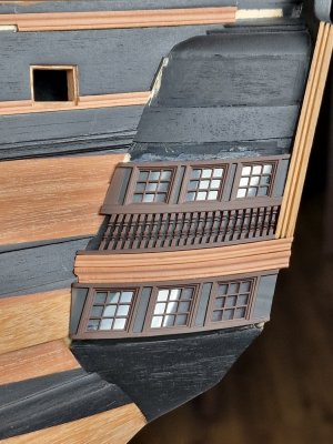
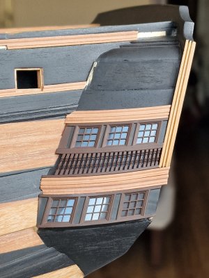
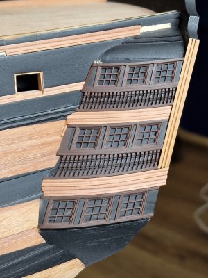
HMS Victory [1805] 1:79 by serikoff. Started with Mantua -> Upgraded with John McKay's Anatomy.

3D - 02 (vol. 1)

Part 23


So, I decided not to create a separate topic about 3D printing but to incorporate certain aspects into the subject of building the stern and showcase everything using it as an example.
02.jpg
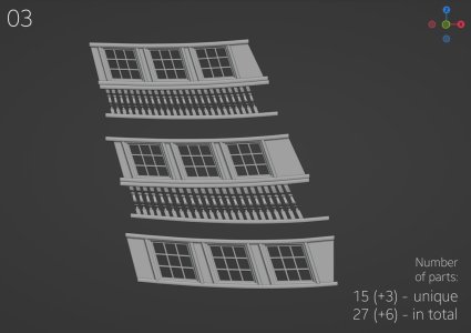
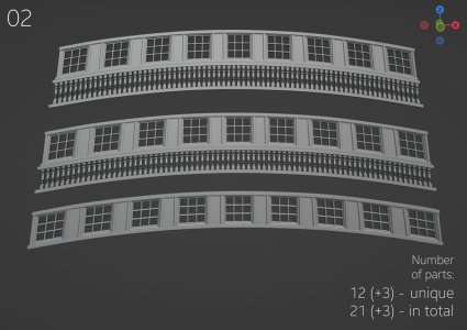
We continue our count of printed parts... (+3) Three unique parts were added, with the total count updated accordingly.

@Chestcutter @Johann H thank you for your interest and questions. I will do my best to answer them now.

To understand the entire process, let’s start from the beginning and go step by step.

I model the parts from scratch using Blender. I learned the program on my own through YouTube tutorials—there’s nothing overly complicated about it.
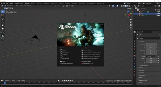
Блендер.jpg

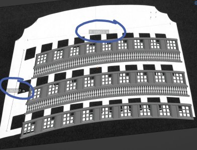
Scale! How do I scale objects? It’s simple. Let’s take the stern as an example. When creating it, I had a drawing of the part that I used to cut the rear panel. I scanned it and imported the image into Blender, which has a ruler tool. I simply adjusted the dimensions in Blender to match the measurements from my paper drawings.
Блендер 2.jpg

Naturally, all of this is done in two planes, but for clarity, I showed it in a three-dimensional format.

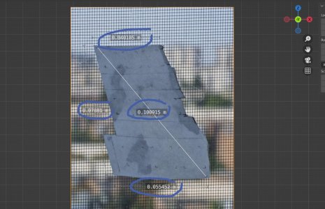
The second method for transferring dimensions involves using telephoto photography—specifically, at least x5 to x10 zoom. This way, the object’s proportions won’t be distorted by perspective. I cut out the part on paper, measure its dimensions to 0.1 mm, and transfer its photo into Blender. There, I use the ruler tool to scale it to the correct dimensions.
Блендер 3.jpg

This method definitely works, even if the parts need to be integrated rather than simply placed, like a cannon.

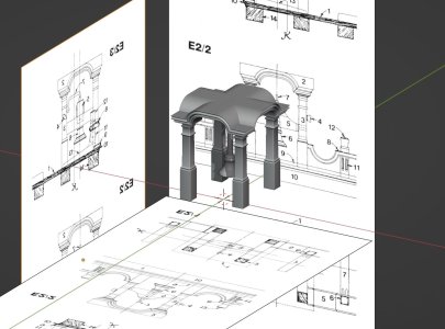
Next comes the design development based on the blueprints. I use the same approach by importing scanned copies into the program, scaling them with the ruler, and ensuring I have 2–3 views (front, side, and top).
Блендер 4.jpg

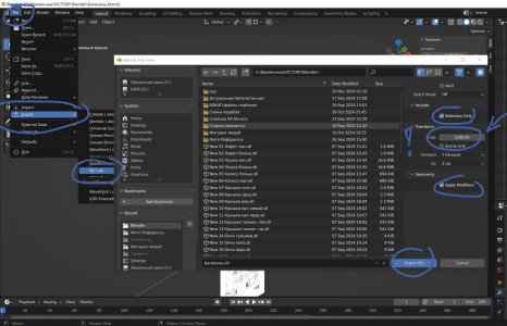
Next, I export the completed part from the program in STL format. If the part is simple, I export it as a whole; if it has a complex shape, I fragment it for easier printing. It’s crucial to export from the program with the parameters shown in the photo below. Scale 1000.00 !!!!!!!!
Блендер 5.jpg

Then, I open these files in the original slicer program for my 3D printer. Here, I arrange the parts for printing. Key considerations for positioning and supports: always position the parts vertically or at a 45-degree angle. **Do NOT place parts flat horizontally** because the lower layers will delaminate without sufficient supports. I've mentioned this before.

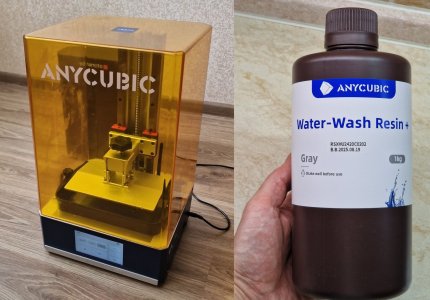
My printer is the Anycubic Photon M3 Plus, and the slicer I use is Anycubic Photon Workshop. I use water-washable resin, as shown in the photo below.
00001.jpg

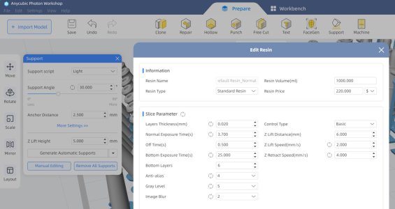
In the slicer settings, you need to specify the following parameters. I arrived at these settings after seven attempts; prior to this, the plastic often detached from the supports.
Блендер 7.jpg

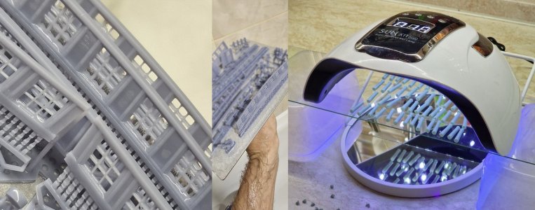
After printing, it's essential to thoroughly rinse the model under water, as the resin is water-washable. After rinsing, you need to cure it with ultraviolet (UV) light. I use my wife's UV lamp for curing gel nails, and it works perfectly for this purpose!
00001ук.jpg
Next, it's essential to sand flat parts with 1500-grit sandpaper. At 20 microns, the layers are less visible on detailed parts, but for flat surfaces, it's recommended to carefully polish them, but not beyond 1500 grit.

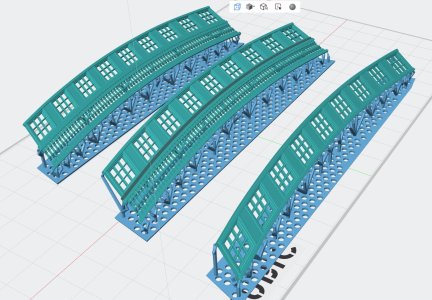
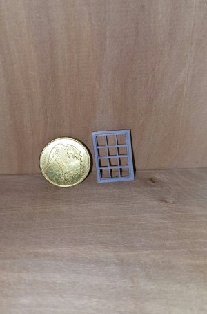
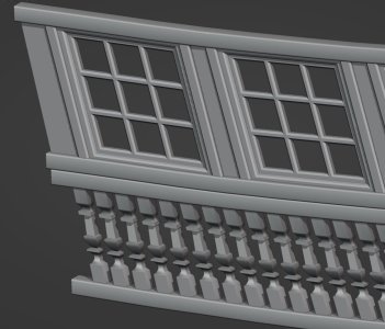
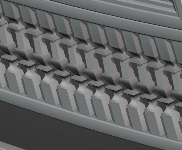
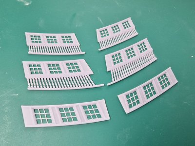
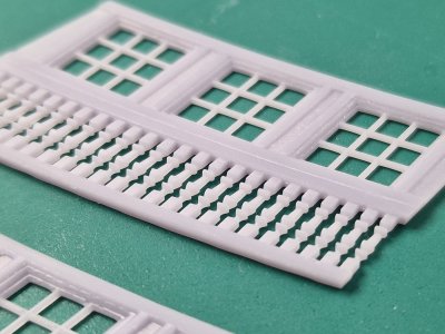
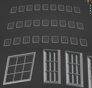
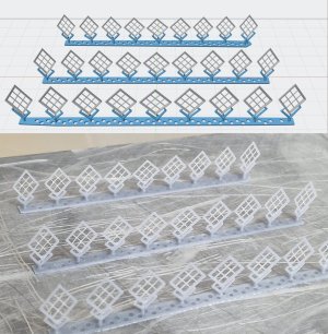
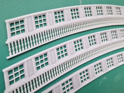
After sanding, you can proceed with painting. I'll discuss this process further in later posts, but for now, a few more points about printing. Initially, I wanted to model only the windows for the gallery (as shown in the photo below). However, when printing, they were so thin that they deformed during curing, as the thickness of the inner frames was less than 0.5 mm. This is something to consider, which is why I decided to model everything together: the frame, the windows, and the columns.
0001.jpg
0002.jpg

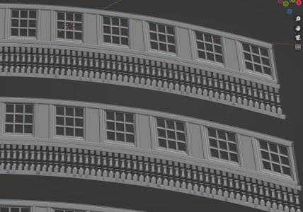
But I decided to go with the idea of creating a solid frame. I modeled and printed it, but...
06.JPG
07.JPG
9.JPG

... once again, there were some issues. The power went out during printing, so another important aspect to consider when printing is having an uninterruptible power supply (UPS). This is essential. However, the defective parts were still used for testing the painting process. And it was during this testing that I realized I needed to reduce the layer thickness and polish the flat surfaces. Below, in the photo, you can see why.

20240905_135027ак.jpg
20240906_114932.jpg

From this experience, I realized that the paint I initially chose was not suitable, so I picked another one that worked perfectly. I will show which one below. I also learned that I need to polish the flat surfaces and make sure to use an uninterruptible power supply. I took note of all these points, and finally, here are the positive results below.

20241012_135114.jpg
20241012_135124.jpg

In the photo above, you can see a slight wave between the supports, which I anticipated by making the lower part wider and then simply polishing it.

20241012_143608.jpg

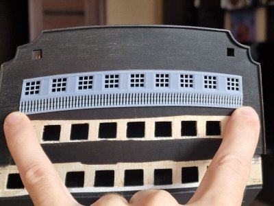
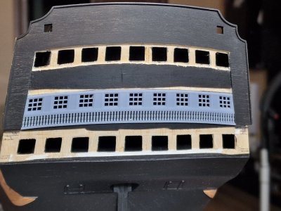
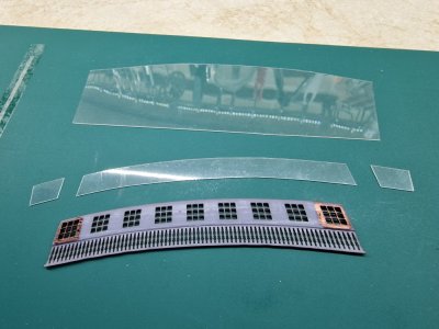
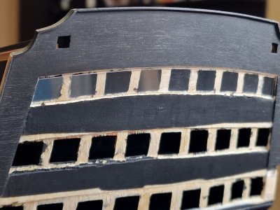
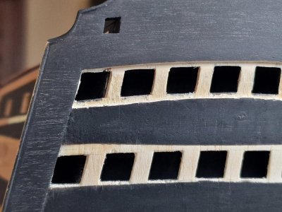
Next, I made cuts for plastic imitation glass windows and tried the parts in place.

20241012_155024.jpg
20241012_155102.jpg
20241012_164142.jpg

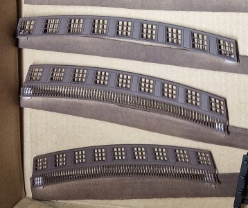
After that, I painted them in the base color, brown...

20241025_111846кув.jpg

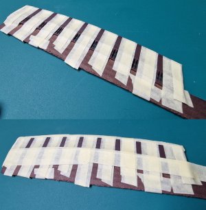
Then, I covered everything except the areas that I later painted in a different color.

20241025_123225уц.jpg

The paint I used for all the details now and in the future is this one. It's a matte camouflage aerosol spray paint based on acrylates, Recoil.

20241122_151439.jpg

In the next part, I will show how I attached the ready parts to the hull...

...
 
I noticed that some of the heart blocks did not have channels to allow for the rigging thread, and I appreciate that you go to some lengths to highlight that your post was about your learning curve and mistakes made, but will successful dead eyes, blocks and hearts need drilling to make them useful?
I forgot to clarify about the deadeyes. Yes. The first ones had problems with printing holes. And I tried to make them bigger, but for the most part they are either very small, if you set the correct diameter, or big, if you deliberately make them much bigger. Therefore, I decided to make the holes minimal so that there would be a simple passage, and then I would be able to drill the diameter I need manually. But I will still try with this.

@Johann H , If you have any questions, please contact us as well.
 
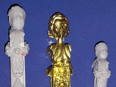
Good tutorial I managed to learn some new things. As for the deformation of windows after curing. I think if you play with settings you could manage to print them 100% correct. I designed from scratch Soleil Royal's cathead support and managed to print even the tiniest flowers in rose at the centrum which certainly is even less then 0,35mm. Resin has a huge capabilities for making even the smallest parts

Also if you want to have exact diameter of hole export the cylinder from blender and import it back with right mm

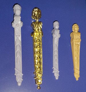
The metal one is from deagostini colletion and on the right is heller's
20241122_205807.jpg
20241122_205541.jpg
20241110_154719.jpg
SR Cathead rose.jpg
 
Last edited:
Good tutorial I managed to learn some new things. As for the deformation of windows after curing. I think if you play with settings you could manage to print them 100% correct. I designed almost from bare scratch Soleil Royal's cathead support and managed to print even the tiniest flowers in rose at the centrum which certainly is even less then 0,35mm. Resin has a huge capabilities for making even the smallest parts

Also if you want to have exact diameter of hole export the cylinder from blender and import it back with right mm

The metal one is from deagostini colletion and on the right is heller's
View attachment 485760
View attachment 485757
View attachment 485767
View attachment 485758
It's not just the thickness of the frames, but the fact that they themselves were very small and they bent right from washing with water. They had no basis for rigidity. In the frames as I later made, not everything was more stable. It's a pity that many people are not so interested in this topic, since I have a lot of information and a lot of photos of experiments. Oh well))) If someone is interested in something else, I can answer, in short, I still described most of it. Next, I will post the assembly of the finished parts. And then we'll see how the skeptics will appreciate it)))
 
It's not just the thickness of the frames, but the fact that they themselves were very small and they bent right from washing with water. They had no basis for rigidity. In the frames as I later made, not everything was more stable. It's a pity that many people are not so interested in this topic, since I have a lot of information and a lot of photos of experiments. Oh well))) If someone is interested in something else, I can answer, in short, I still described most of it. Next, I will post the assembly of the finished parts. And then we'll see how the skeptics will appreciate it)))
That's weird our windows are preety similar in scale and dimensions, so I think you shouldn't have problems with printing them separetly without any problems.
Have you tried diffrent resins or changing Lift speed and Bottom lift speed? Slowing that parameters can be beneficial when expecting highest details
I repeat, it printed perfectly, as you can see in the photo. The print quality was simply at the highest level, like the thickness of a hair. But when the product was washed with water from the stream of water, these thin sticks simply bent like a rope and stretched, deformed and hardened. I tried to wash more carefully, and there was less deformation, but it still appeared even from the fact that if you place the window horizontally, its inner part sags like a net and hardens. Yes, I tried all the printing options, it's just that very thin and long sticks stretch and deform. But it is as it is, I still really liked the result)))
 
3D - 02 (vol. 2)

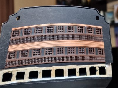
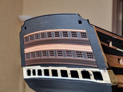
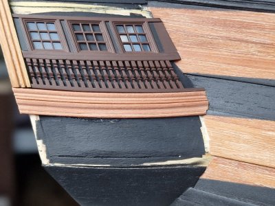
With the technical part sorted, it’s time to secure the details onto the hull.
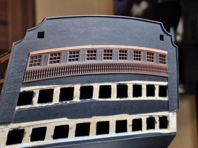
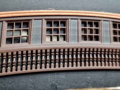
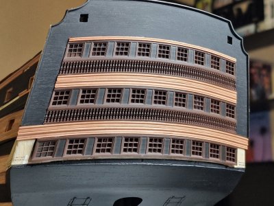
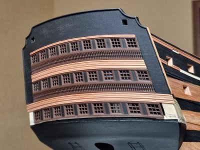
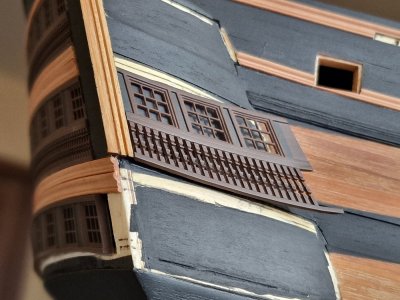
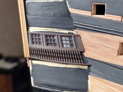
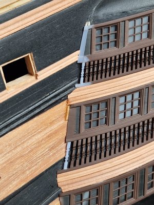
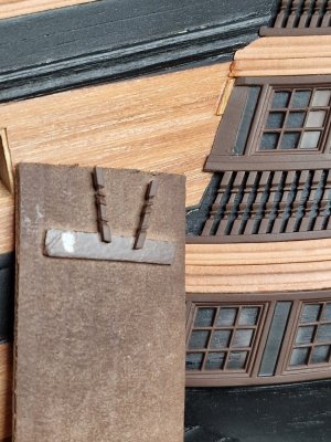
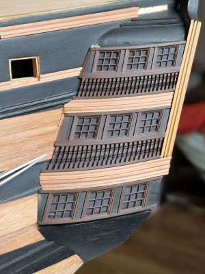
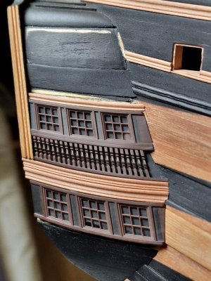
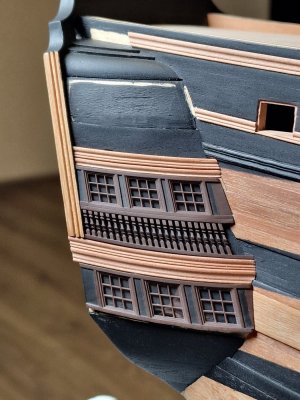
Since I had already adjusted all the parts to fit their designated spots before painting, all that remained was to glue them in place. First, I had to create plastic plates to imitate window glass, and then cover them with the printed details.

HMS Victory 656.jpg
HMS Victory 657.jpg
HMS Victory 658.jpg

On top, I glued a decorative rail made from pink pearwood. Like the rest, it will darken significantly after being treated with oil, so the color difference won’t be as noticeable.

HMS Victory 659.jpg

Unfortunately, attaching this type of detail is quite challenging. PVA glue doesn’t bond with plastic, and I only use gel cyanoacrylate glue because the liquid version dries faster than I can position the piece correctly. This occasionally causes minor glue smudges, and in some spots, paint might chip off. These imperfections are very small and barely noticeable, but they still frustrated me. However, I eventually found a way to carefully camouflage these tiny flaws with regular acrylic paint. Therefore, once all the pieces are secured, I’ll go back and touch up these areas as needed. For now, please don’t focus too much on them.
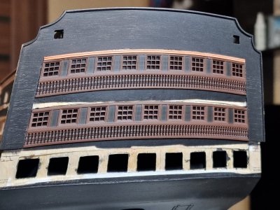
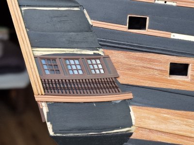
The upper tier was aligned with the top edge, while the middle tier was positioned based on the lower edges of the side plates.

HMS Victory 660.jpg

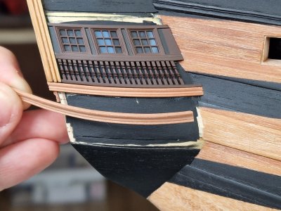
Between these details, I glued two decorative rails made from the same pink pearwood.

HMS Victory 661.jpg
HMS Victory 662.jpg

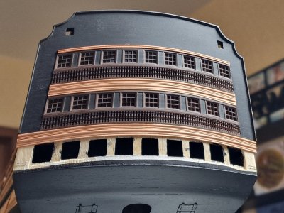
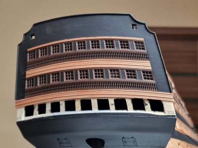
After that, additional rails were attached...

HMS Victory 663.jpg
HMS Victory 664.jpg

...and finally, the lower window frame was secured.

HMS Victory 665.jpg
HMS Victory 666.jpg

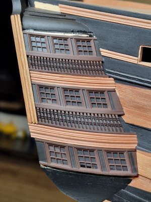
There will be three more levels of rails below, along with several details on the lower sides—not including decorative elements, which will come much later. Next, I will attach the side frames of the stern gallery.

Ship-1
 
3D - 03 (vol. 1)

Part 24


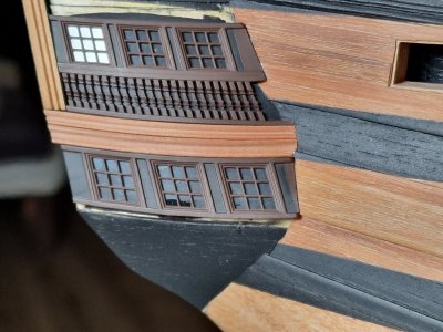
The same steps were repeated for the side window frames.

HMS Victory 667.jpg
HMS Victory 667s.JPG
HMS Victory 667d.JPG

Before painting, I first ensured the frames had the correct geometry so that their edges fit perfectly into place. This, by the way, was not easy to achieve. There were no exact parameters, and everything had to be adjusted countless times to ensure a tight, gap-free fit. However, not everything worked out perfectly, and I had to make minor corrections to several details. For this reason, I printed multiple copies of each part as a precaution.

HMS Victory 668.jpg
HMS Victory 669.jpg

Initially, I planned to cut openings for the windows, as I did for the rear gallery. However, I decided against it. The window profiles are not flat, and bending the frames to match the curve would risk damaging the cut base. Instead, I chose to simply paint the areas under the windows. When covered with the plastic that imitates glass, the result looked almost identical to what it would have been with actual cutouts.

HMS Victory 670.jpg

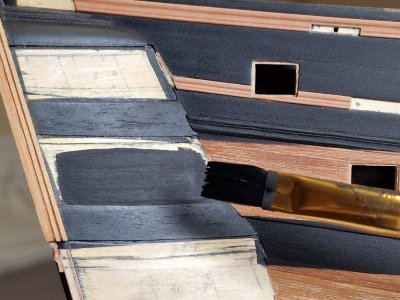
I painted the frames with regular acrylic paint, slightly diluted with water. Afterward, I simply glued the frames in place. First, I secured one side using gel cyanoacrylate, then applied adhesive to the other side and fixed it as well.

HMS Victory 671.jpg
HMS Victory 672.jpg

Next, I attached a molding made of pink pearwood. Once again, I remind you that the pearwood will darken significantly after being treated with oil. To ensure the moldings fit properly, I first shaped them with a dry iron.

HMS Victory 673.jpg
HMS Victory 674.jpg

HMS Victory 675.jpg

Afterward, I glued the lower frame, and here is where the first mishap occurred... Some glue seeped under the plastic, leaving a glossy stain on the middle window. Honestly, I was really upset... but I hesitated to redo it, deciding to see if similar issues would arise further down the line.

HMS Victory 676.jpg

Above, the process was the same: molding, molding, and then another frame.

HMS Victory 677.jpg
HMS Victory 678.jpg
HMS Victory 679.jpg

The same steps will be repeated on the opposite side, mirrored, but that will be covered in the next part.
...
 
Last edited:
Very nice, Sergey. I am impressed that you were able to get everything to fit so nicely dimensionally. That couldn't have been easy with the different planes.
Yes, it was not easy. First I scanned the place, then transferred it to a 3D program and did it with a margin at the edges. Then I adjusted it to the place. But there were a couple of miscalculations))) I will talk about this in the next part. But everything was solved)
 
3D - 02 (vol. 1)

Part 23


So, I decided not to create a separate topic about 3D printing but to incorporate certain aspects into the subject of building the stern and showcase everything using it as an example.

View attachment 485566
We continue our count of printed parts... (+3) Three unique parts were added, with the total count updated accordingly.

@Chestcutter @Johann H thank you for your interest and questions. I will do my best to answer them now.

To understand the entire process, let’s start from the beginning and go step by step.

I model the parts from scratch using Blender. I learned the program on my own through YouTube tutorials—there’s nothing overly complicated about it.

View attachment 485567

Scale! How do I scale objects? It’s simple. Let’s take the stern as an example. When creating it, I had a drawing of the part that I used to cut the rear panel. I scanned it and imported the image into Blender, which has a ruler tool. I simply adjusted the dimensions in Blender to match the measurements from my paper drawings.

View attachment 485570

Naturally, all of this is done in two planes, but for clarity, I showed it in a three-dimensional format.

The second method for transferring dimensions involves using telephoto photography—specifically, at least x5 to x10 zoom. This way, the object’s proportions won’t be distorted by perspective. I cut out the part on paper, measure its dimensions to 0.1 mm, and transfer its photo into Blender. There, I use the ruler tool to scale it to the correct dimensions.

View attachment 485571

This method definitely works, even if the parts need to be integrated rather than simply placed, like a cannon.

Next comes the design development based on the blueprints. I use the same approach by importing scanned copies into the program, scaling them with the ruler, and ensuring I have 2–3 views (front, side, and top).

View attachment 485572

Next, I export the completed part from the program in STL format. If the part is simple, I export it as a whole; if it has a complex shape, I fragment it for easier printing. It’s crucial to export from the program with the parameters shown in the photo below. Scale 1000.00 !!!!!!!!

View attachment 485574

Then, I open these files in the original slicer program for my 3D printer. Here, I arrange the parts for printing. Key considerations for positioning and supports: always position the parts vertically or at a 45-degree angle. **Do NOT place parts flat horizontally** because the lower layers will delaminate without sufficient supports. I've mentioned this before.

My printer is the Anycubic Photon M3 Plus, and the slicer I use is Anycubic Photon Workshop. I use water-washable resin, as shown in the photo below.

View attachment 485607

In the slicer settings, you need to specify the following parameters. I arrived at these settings after seven attempts; prior to this, the plastic often detached from the supports.

View attachment 485584

After printing, it's essential to thoroughly rinse the model under water, as the resin is water-washable. After rinsing, you need to cure it with ultraviolet (UV) light. I use my wife's UV lamp for curing gel nails, and it works perfectly for this purpose!

View attachment 485608
Next, it's essential to sand flat parts with 1500-grit sandpaper. At 20 microns, the layers are less visible on detailed parts, but for flat surfaces, it's recommended to carefully polish them, but not beyond 1500 grit.

After sanding, you can proceed with painting. I'll discuss this process further in later posts, but for now, a few more points about printing. Initially, I wanted to model only the windows for the gallery (as shown in the photo below). However, when printing, they were so thin that they deformed during curing, as the thickness of the inner frames was less than 0.5 mm. This is something to consider, which is why I decided to model everything together: the frame, the windows, and the columns.

View attachment 485589
View attachment 485590

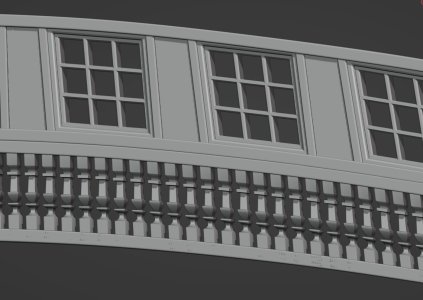
But I decided to go with the idea of creating a solid frame. I modeled and printed it, but...
View attachment 485591
View attachment 485592
View attachment 485593

... once again, there were some issues. The power went out during printing, so another important aspect to consider when printing is having an uninterruptible power supply (UPS). This is essential. However, the defective parts were still used for testing the painting process. And it was during this testing that I realized I needed to reduce the layer thickness and polish the flat surfaces. Below, in the photo, you can see why.
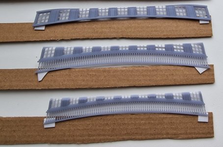
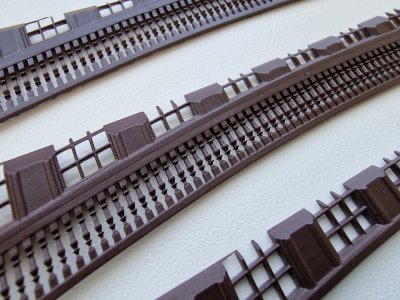
View attachment 485596
View attachment 485597

From this experience, I realized that the paint I initially chose was not suitable, so I picked another one that worked perfectly. I will show which one below. I also learned that I need to polish the flat surfaces and make sure to use an uninterruptible power supply. I took note of all these points, and finally, here are the positive results below.
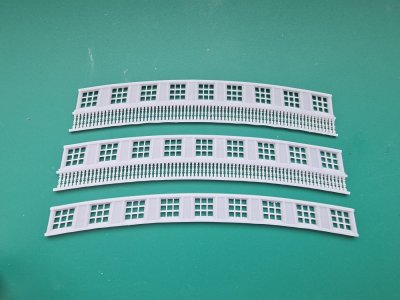
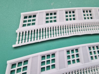
View attachment 485599
View attachment 485600

In the photo above, you can see a slight wave between the supports, which I anticipated by making the lower part wider and then simply polishing it.
View attachment 485601

Next, I made cuts for plastic imitation glass windows and tried the parts in place.
View attachment 485603
View attachment 485604
View attachment 485605

After that, I painted them in the base color, brown...
View attachment 485606

Then, I covered everything except the areas that I later painted in a different color.
View attachment 485609

The paint I used for all the details now and in the future is this one. It's a matte camouflage aerosol spray paint based on acrylates, Recoil.

View attachment 485611

In the next part, I will show how I attached the ready parts to the hull...

...
Thanks Sergey for providing a detailed explanation on how you make these parts and the technology involved.

I will do some research on Blender.

You are inspirational in your pursuit of excellence.
 
Thanks Sergey for providing a detailed explanation on how you make these parts and the technology involved.

I will do some research on Blender.

You are inspirational in your pursuit of excellence.
I am sincerely glad to hear it! I was glad to help. If you have any questions, please contact me. There are many tutorials on this program on the Internet, it is a very interesting thing.)))

By the way, I found a scan of Nelson's statue. I added a general's hat to it in Blender and printed it out. I'll color it if possible and when I do things on the deck, I'll put it next to it to visualize the scale of the real ship. I'll write about it sometime)
Screenshot_20241125_184945_Gallery.jpg
 
Last edited:
3D - 03 (vol. 2)

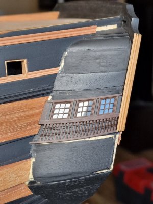
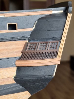
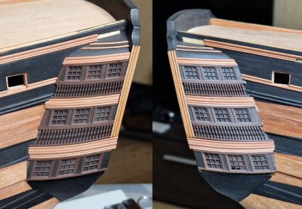
On the opposite side, everything was identical (mirrored).

HMS Victory 680.jpg
HMS Victory 681.jpg
HMS Victory 682.jpg
HMS Victory 683.jpg

Here, however, I encountered the first discrepancy—a part turned out to be slightly too short. Fortunately, I had spares, so I added a fragment to fill the gap and then painted over the joint. Additionally, I placed one column in each frame, as the empty spaces looked visually excessive.

HMS Victory 684.jpg
HMS Victory 685.jpg
HMS Victory 686.jpg
HMS Victory 687.jpg
HMS Victory 688.jpg

At the top, I glued a wide molding and two narrower ones in the areas where there were steps to accommodate them.
All that remains are the three lower levels of decorative moldings and two square inserts, after which the gallery will be complete (not counting the decorative elements). So, just one more small post, and then I'll move on to the hull, preparing it for the copper plating.
...
 
Below are my thoughts - no judgements.

On one hand I see the advantage of the laser printer - it yields "perfect'' parts which is especially nice when dealing with things like canon carriages and other parts of which there are multiple pieces everything is uniform. And the laser printer parts won't show any imperfections inherent with parts that are hand cut from etched board, sanded, etc.

I don't think it should be called cheating. I just think that it defeats to objective of creating something by hand through skill and patience.

In light of my lack of skill perhaps I should get a laser printer and do as you do . It might make my work more pleasing to the eye. At this point however I'll continue to try to improve my skills and deal with the parts supplied with the kits.
You are absolutely right in your statements. The only thing is that many still consider it cheating or deception, but this is their right. I like wood more than plastic, but ... as I already said, to make a lot of repeatable parts well, you need machines, which I do not have. Doing 100500 columns by hand is a pain)) That's why I make everything from wood except for those parts that are under paint and of which there are many. Plus, I like modeling and this is also a hobby, so I do not understand those who have a bad attitude to 3D. The same can be said about milling parts on a milling machine, then this is cheating, or if it is wood, then it is possible?)) It turns out to be double standards. You are doing the right thing by trying to do everything yourself from wood, this is very commendable. But I think that when your skills improve, you will want to speed up the construction process a little)) Thank you for your comment, I will be glad if you continue to follow the construction. If you have any questions, please contact me.
 
Hello Sergey,

I am enjoying watch your work and am learning a great deal from your postings.

I feel that most important component of building is that we enjoy and get gratification from what we are doing. I have been building models of some type for most of my life. Whether it was plastic model cars, airplanes, ships, or scale r/c aircraft or now wooden model ships, most of all, I have enjoyed the adventure. If it wasn't for people like you and the others on this great site who share their knowledge, I wouldn't be able to build wooden ships.

Thanks,
Bill
Thank you for your kind words. Yes, you are right, I just like what I do. Whether it is building a wooden ship, or modeling parts. I can say that it is not so easy to model some part in a program. How is it different from doing it manually? I am glad that my photos and stories help someone, teach or just motivate. I am far from being a master to be equal to, there are many modelers much better than me, but I like to help at least with what I do. ))
 
Your comment about people not wanting to learn more about 3D may be true, but I think it more that they are afraid to get into all the work needed.

I have 3D resin printed some things for my model railroad hobby and wasted more than I got usable prints, due to learning process.

The old saying "If you first don't succeed, try again and again, until you succeed" is very true.
Absolutely right. I myself have done a lot of trial and error until I have achieved more or less a result. Working on mistakes, constant improvements also take time, but if you like it, then this time is your hobby)) I think that some modelers are simply categorically for classical methods (wood and metal). I respect their choice, for me they are the level to which one should strive... but life is one. I want to learn something new, and I don’t want to routinely make 100 parts and spend a lot of time on it because there is no machine that would speed up the process for you.. and time is not infinite.... Thank you for your comment!

 
Back
Top