-

Win a Free Custom Engraved Brass Coin!!!
As a way to introduce our brass coins to the community, we will raffle off a free coin during the month of August. Follow link ABOVE for instructions for entering.
-

PRE-ORDER SHIPS IN SCALE TODAY!
The beloved Ships in Scale Magazine is back and charting a new course for 2026!
Discover new skills, new techniques, and new inspirations in every issue.
NOTE THAT OUR FIRST ISSUE WILL BE JAN/FEB 2026
You are using an out of date browser. It may not display this or other websites correctly.
You should upgrade or use an alternative browser.
You should upgrade or use an alternative browser.
HMS Victory [1805] 1:79 by serikoff. Started with Mantua -> Upgraded with John McKay's Anatomy.
08.2024
I mentioned this would be my final diary post, but I forgot about a section I had skipped earlier and decided to include it at the end. This part is about 3D modeling and printing. It will be extensive, and those interested in this topic will find plenty of useful insights. But for now, let’s wrap up the head rails.
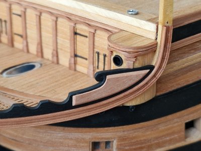
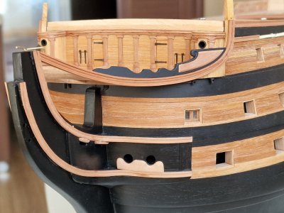
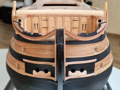
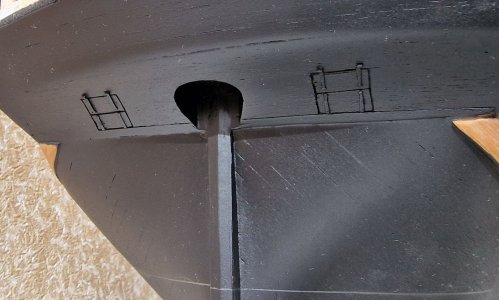
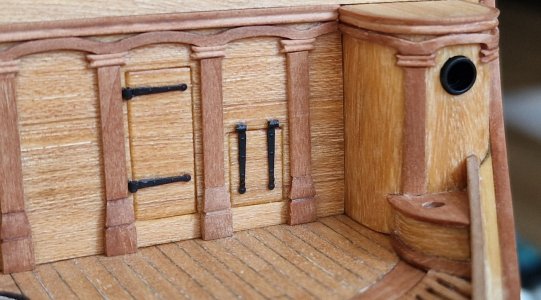
Incidentally, I will briefly touch on some 3D-printed details here, but only on the surface to avoid repetition later. The first such detail is the hinges for gun ports and doors. I’ve already shown them when attaching the hinges to the gun ports under the gallery. Here, I glued similar hinges onto the head rail’s gallery.
All the hinges were designed, printed, and painted by me (I’ll delve into this process in detail later). I’d like to make a quick point. Yes, many people don’t take 3D-printed details seriously, but I think I can at least partially change your perspective. For now, though, you can see how these parts look alongside wooden elements in the finished example. AH... I also forgot that I also printed the windows of the toilets))
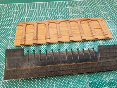
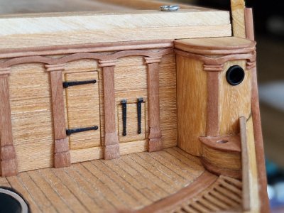
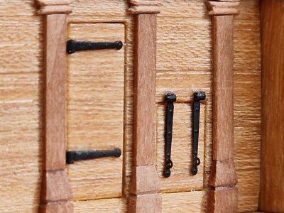
In my opinion, under paint and at this scale, everything looks great. The details are visible—hinges, rings—and the main advantage is that I can print as many of these hinges as I need right at home with my printer!
Let’s move on. Once again, we’re back to the toilets, now in a paired design. From the photos, I think the process of how they were made will be clear.
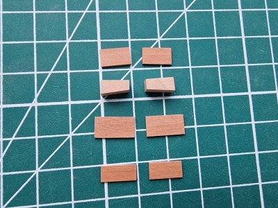
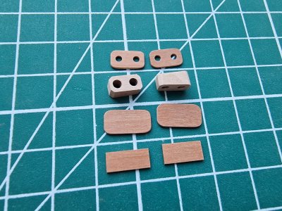
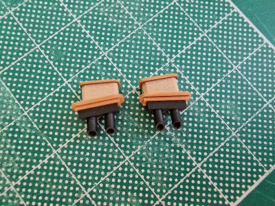
The lower parts were painted, and although the pieces are assembled, they have not yet been glued to the hull.
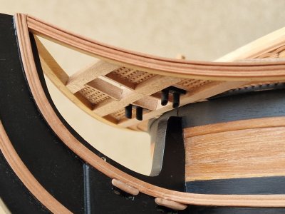
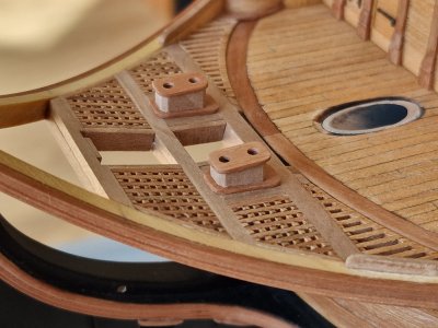
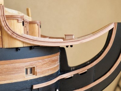
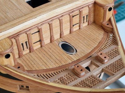
And finally, I completed the work on the head with decorative inserts.
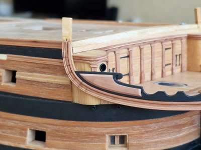
For now, that's all. I'll return to the ship's bow later. And now... my favorite—3D modeling (in the next part).
For the record, there are 4,050 parts on board

I mentioned this would be my final diary post, but I forgot about a section I had skipped earlier and decided to include it at the end. This part is about 3D modeling and printing. It will be extensive, and those interested in this topic will find plenty of useful insights. But for now, let’s wrap up the head rails.
Incidentally, I will briefly touch on some 3D-printed details here, but only on the surface to avoid repetition later. The first such detail is the hinges for gun ports and doors. I’ve already shown them when attaching the hinges to the gun ports under the gallery. Here, I glued similar hinges onto the head rail’s gallery.
All the hinges were designed, printed, and painted by me (I’ll delve into this process in detail later). I’d like to make a quick point. Yes, many people don’t take 3D-printed details seriously, but I think I can at least partially change your perspective. For now, though, you can see how these parts look alongside wooden elements in the finished example. AH... I also forgot that I also printed the windows of the toilets))


In my opinion, under paint and at this scale, everything looks great. The details are visible—hinges, rings—and the main advantage is that I can print as many of these hinges as I need right at home with my printer!
Let’s move on. Once again, we’re back to the toilets, now in a paired design. From the photos, I think the process of how they were made will be clear.


The lower parts were painted, and although the pieces are assembled, they have not yet been glued to the hull.


And finally, I completed the work on the head with decorative inserts.


For now, that's all. I'll return to the ship's bow later. And now... my favorite—3D modeling (in the next part).
For the record, there are 4,050 parts on board

As I already said, I will make a comparative post of three oils and will discuss this point too. But I will make a spoiler for you that linseed oil without an ultraviolet filter and in the sun the wood under it can very well darken, I checked this, but more about this later, when I will have delayed results of all the oils, be patient, it will be interesting))From my little experince with linseed oil I can tell you it changes the color of wood very subtly. After puting oil it is intense but it changes back to slightly highlighted original color after some time
Dzięki. Tak, foka wygląda przyzwoicie, jeśli zrobisz to dobrze.Witaj
Dziób wygląda bardzo ładnie wydruki są 3D są świetne, piękna ładna dokładna praca. Pozdrawiam Mirek
Then you will be interested in everything that I will soon publish. I made a sample of linseed oil last year, and gave it harsh conditions. On the balcony in the heat and on the finger of the sun. Of course, this will not happen in the room conditions, but I sped up what can happen in years. So, the sample darkened a lot. A little later I will show the difference.Good results with printed hinges they're also on my to do list.
How much time it took to darken? After couple of months I still can't see the difference or it's very slight
Hi SergeyHello everyone! Today, I’ll try to post the final part about the head rails... But for now, I wanted to share some news. Once again, I’ll be testing some samples, as I’ve ordered tung oil. I’m waiting for delivery, but unfortunately, I’ve run out of pearwood veneer, and I can’t remember where I got it. Now I’ll have to look for it elsewhere.
I think I’ll move away from teak oil—it has its pros, but also some cons. The way it interacts with bitumen has its nuances, which I’ll discuss later. Tung oil appeals to me because it’s matte and allows for gluing over it. In short, I’ll test it and then do a big comparison of three oils: linseed, teak, and tung. I’m also missing Danish oil, but who knows, maybe I’ll try that one too eventually. Still, I hope tung oil will be the one I settle on—as long as the tests meet my expectations.
View attachment 484775
Looking forward to your analysis of those 3 (or 4) options
Cheers
Part (15)
06.2023 - 10.2024
So, we’ve gradually arrived at the present… well, almost. To truly start, we need to take another step back into the past. The topic is quite extensive. I’m not sure how many posts it will take before I get to showcasing the actual construction, but a prologue is unavoidable. The introductory section will be titled:
"Trials and Errors" in
3D Modeling and 3D Printing.
The model features a significant amount of carved decorative elements. While this particular ship doesn’t have an overwhelming amount, there are still notable pieces, such as the figurehead, the patterns surrounding it, the stern gallery, and numerous other carved details. These need to be created somehow. Ready-made options that fit my scale are either nonexistent, of poor quality, or prohibitively expensive. Hand-carving them or ordering CNC work wasn’t an option for me. So, I needed another solution.
That’s when I came up with a promising idea: **scanning figurines** (wherever I could find them) and then adjusting them in a 3D modeling program to fit my requirements.
Later, I had an even crazier idea: **scanning the entire model** and using that scan to create nearly everything—deck details, rigging, and more. However, I soon abandoned that notion, deciding instead to maximize the use of wooden components. Despite this, the idea of using 3D modeling for decorative elements remained viable.
I managed to acquire a figurehead and several other tin parts from colleagues who were building using partwork kits...
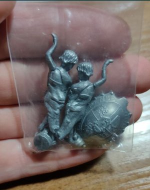
I was able to acquire several other decorative elements from DeAgostini assembly magazines. I scanned all of them using an intraoral scanner—being a dentist, this was no trouble for me.
This method allowed me to capture highly detailed digital replicas of the parts, which I could then modify in 3D modeling software to better suit my project. It turned out to be an efficient and precise solution for replicating intricate decorative elements.
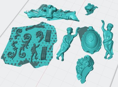
The quality of the scans wasn’t perfect, but they provided a solid foundation for further modeling. Specifically, they served as a base for design corrections in **Blender**, where I could adjust the scale, enhance the level of detail, and fix any imperfections. This approach will come into play later when I focus on refining the primary decorative elements.
For now, I’ll list all the key trials and errors, along with the corresponding solutions, below. Let’s get started!
1. Scale Issues
Each model has its specific scale, but it’s crucial not to overlook the technical limitations of your 3D printer. While you can design details down to a micron, the printer might not be able to reproduce them accurately.
I encountered this issue while printing cannons. The rings and eyelets on the carriages were so thin that even if they printed successfully, they broke during post-processing.
Solution:
In subsequent designs, I accounted for this by increasing the thickness of rings and other fragile details. Additionally, some elements need to be intentionally exaggerated in size because they would otherwise be invisible on the model. Balancing realism with practicality is essential when working with such small-scale projects.
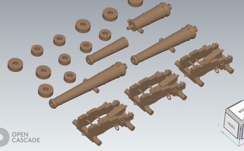
By the way, I didn’t initially plan to delve deeply into this topic, and since my wife was familiar with the 3D program Blender, she was the one who modeled the first cannons and carriages for me. However, I later realized that it was interesting, and I started studying everything in detail myself. In the photo below, you can see a model printed with small elements that broke. Next, I will show how I changed everything. In the meantime, on to the next point...
2. Positioning and supports.
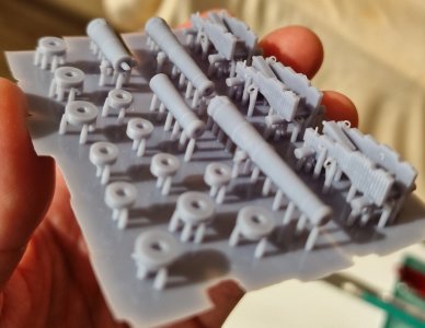
When printing, it’s crucial how you position the part. Avoid placing it horizontally. This will result in numerous supports, the part may warp into an arch during curing, and most importantly, flat surfaces can detach and cause the print layers to delaminate. Regarding supports, don’t position them so that their flat areas rest against the part. In such cases, they’ll be difficult to remove without damaging the part.
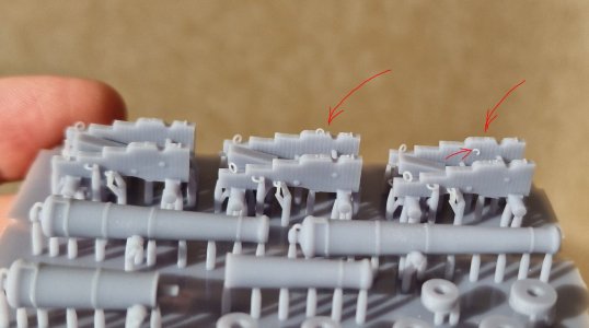
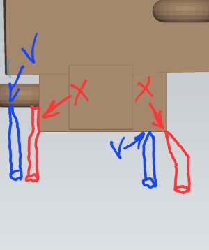
Solution: Position parts either vertically or at a 45-degree angle (depending on the part itself; I’ll show examples later). Place supports manually so that only their tips touch the model, not their bodies.
Also, avoid creating a single continuous base for all elements, as it will deform and result in defects. Instead, divide all elements into groups or separate them so that the base is fragmented.
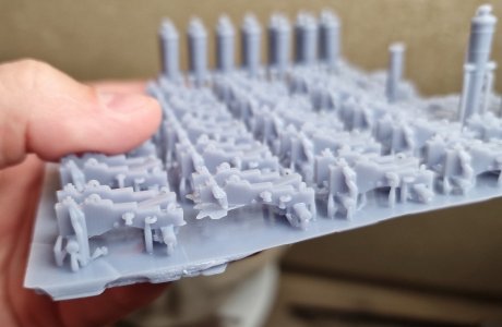
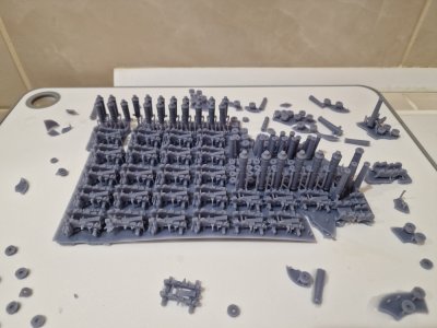
Incorrect positioning (the carriages placed horizontally, plus it will be difficult to align the surface of the gun barrel after the supports).
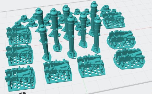
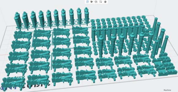
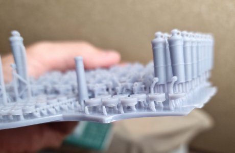
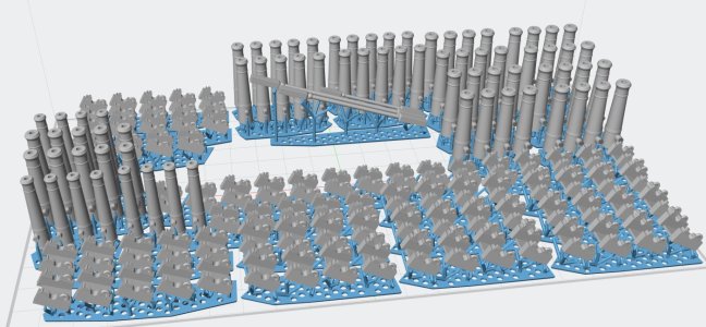
Correct positioning (the carriages at an angle, and the guns with the rounded part facing down, which will be easier to polish after removing the supports).
3. Painting and Preliminary Processing. Print Layers!
I combined these two points into one because the end result for us is a painted part. The most important aspect of its appearance after painting is the visualization of the print layers. I recommend using only photopolymer printing and only at 20 microns, no more. I tried 10 microns, but it increases the risk of defects, and at 30 microns, the print layers (steps) become clearly visible. As for painting, you should only choose deep matte aerosol acrylic paints. I tried others – neither enamel nor other options work. Enamel gives a plastic effect, while not matte paints give a toy-like effect. I chose matte camouflage aerosol paints based on acrylics for myself. The photo below shows the print layers and how the wrong paint looks.
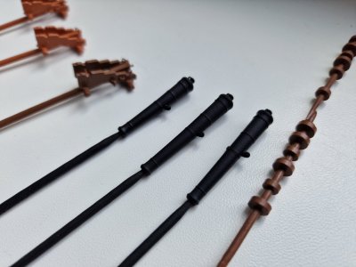
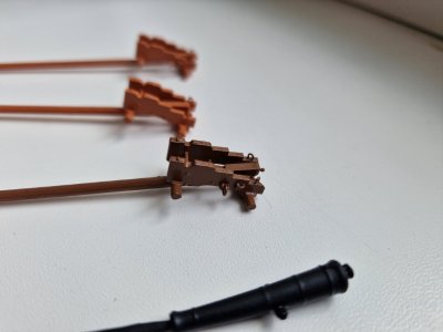
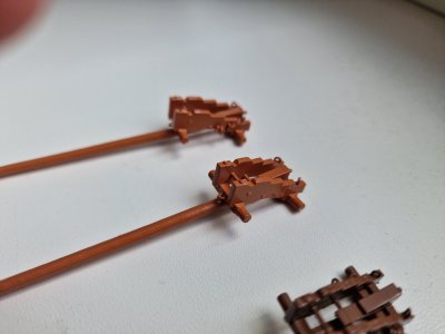
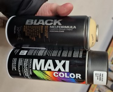
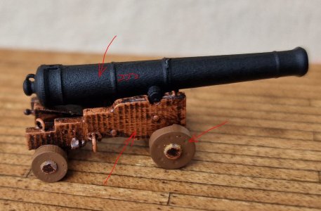
I’ll repeat! These are unsuccessful attempts. And this paint is not suitable. The one that works for plastic will be shown in the next posts.
The material on 3D printing is still in progress, and I will continue to talk about mistakes and nuances in future posts. What I wanted to add is that over time, I got better at modeling, and here are a couple of samples.
Some of this I have already redone... and not just once, fortunately, I got a printer at home (I took it from work when we did an update there), so now I can print whatever I want and as much as I want.
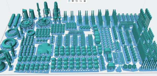
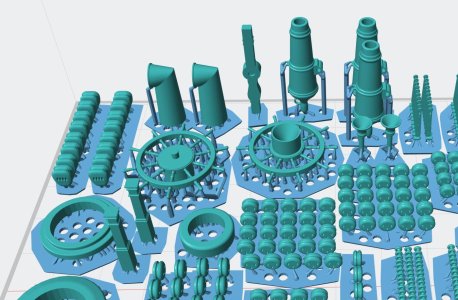
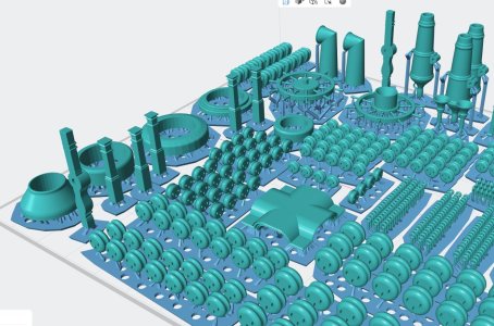
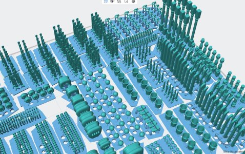
I will go into more detail about all this later with specific examples, but for now, I just kept printing and painting...
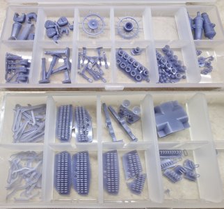
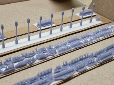
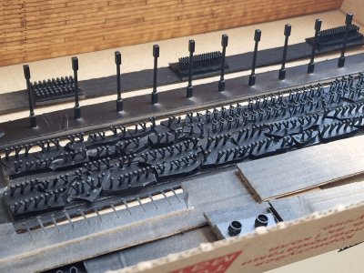
In the upcoming posts, I will talk about and show the final models and how I process and paint the printed details. And of course, I will demonstrate how I adapt these details into the wooden hull so that they don't look toy-like, but rather as if they are made of wood, just painted.

06.2023 - 10.2024
So, we’ve gradually arrived at the present… well, almost. To truly start, we need to take another step back into the past. The topic is quite extensive. I’m not sure how many posts it will take before I get to showcasing the actual construction, but a prologue is unavoidable. The introductory section will be titled:
"Trials and Errors" in
3D Modeling and 3D Printing.
Note! This post contains many photos with mistakes, unsuccessful experiments, and trials, and I repeat – MISTAKES. Please do not perceive these results as representative of 3D printing as a whole. I just want to show what to avoid, and later in the posts, I will present the successful results!
The model features a significant amount of carved decorative elements. While this particular ship doesn’t have an overwhelming amount, there are still notable pieces, such as the figurehead, the patterns surrounding it, the stern gallery, and numerous other carved details. These need to be created somehow. Ready-made options that fit my scale are either nonexistent, of poor quality, or prohibitively expensive. Hand-carving them or ordering CNC work wasn’t an option for me. So, I needed another solution.
That’s when I came up with a promising idea: **scanning figurines** (wherever I could find them) and then adjusting them in a 3D modeling program to fit my requirements.
Later, I had an even crazier idea: **scanning the entire model** and using that scan to create nearly everything—deck details, rigging, and more. However, I soon abandoned that notion, deciding instead to maximize the use of wooden components. Despite this, the idea of using 3D modeling for decorative elements remained viable.
I managed to acquire a figurehead and several other tin parts from colleagues who were building using partwork kits...

I was able to acquire several other decorative elements from DeAgostini assembly magazines. I scanned all of them using an intraoral scanner—being a dentist, this was no trouble for me.
This method allowed me to capture highly detailed digital replicas of the parts, which I could then modify in 3D modeling software to better suit my project. It turned out to be an efficient and precise solution for replicating intricate decorative elements.

The quality of the scans wasn’t perfect, but they provided a solid foundation for further modeling. Specifically, they served as a base for design corrections in **Blender**, where I could adjust the scale, enhance the level of detail, and fix any imperfections. This approach will come into play later when I focus on refining the primary decorative elements.
For now, I’ll list all the key trials and errors, along with the corresponding solutions, below. Let’s get started!
1. Scale Issues
Each model has its specific scale, but it’s crucial not to overlook the technical limitations of your 3D printer. While you can design details down to a micron, the printer might not be able to reproduce them accurately.
I encountered this issue while printing cannons. The rings and eyelets on the carriages were so thin that even if they printed successfully, they broke during post-processing.
Solution:
In subsequent designs, I accounted for this by increasing the thickness of rings and other fragile details. Additionally, some elements need to be intentionally exaggerated in size because they would otherwise be invisible on the model. Balancing realism with practicality is essential when working with such small-scale projects.

By the way, I didn’t initially plan to delve deeply into this topic, and since my wife was familiar with the 3D program Blender, she was the one who modeled the first cannons and carriages for me. However, I later realized that it was interesting, and I started studying everything in detail myself. In the photo below, you can see a model printed with small elements that broke. Next, I will show how I changed everything. In the meantime, on to the next point...


2. Positioning and supports.
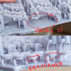
When printing, it’s crucial how you position the part. Avoid placing it horizontally. This will result in numerous supports, the part may warp into an arch during curing, and most importantly, flat surfaces can detach and cause the print layers to delaminate. Regarding supports, don’t position them so that their flat areas rest against the part. In such cases, they’ll be difficult to remove without damaging the part.
Solution: Position parts either vertically or at a 45-degree angle (depending on the part itself; I’ll show examples later). Place supports manually so that only their tips touch the model, not their bodies.
Also, avoid creating a single continuous base for all elements, as it will deform and result in defects. Instead, divide all elements into groups or separate them so that the base is fragmented.


Incorrect positioning (the carriages placed horizontally, plus it will be difficult to align the surface of the gun barrel after the supports).


Correct positioning (the carriages at an angle, and the guns with the rounded part facing down, which will be easier to polish after removing the supports).

3. Painting and Preliminary Processing. Print Layers!
I combined these two points into one because the end result for us is a painted part. The most important aspect of its appearance after painting is the visualization of the print layers. I recommend using only photopolymer printing and only at 20 microns, no more. I tried 10 microns, but it increases the risk of defects, and at 30 microns, the print layers (steps) become clearly visible. As for painting, you should only choose deep matte aerosol acrylic paints. I tried others – neither enamel nor other options work. Enamel gives a plastic effect, while not matte paints give a toy-like effect. I chose matte camouflage aerosol paints based on acrylics for myself. The photo below shows the print layers and how the wrong paint looks.


I’ll repeat! These are unsuccessful attempts. And this paint is not suitable. The one that works for plastic will be shown in the next posts.
The material on 3D printing is still in progress, and I will continue to talk about mistakes and nuances in future posts. What I wanted to add is that over time, I got better at modeling, and here are a couple of samples.
Some of this I have already redone... and not just once, fortunately, I got a printer at home (I took it from work when we did an update there), so now I can print whatever I want and as much as I want.


I will go into more detail about all this later with specific examples, but for now, I just kept printing and painting...


In the upcoming posts, I will talk about and show the final models and how I process and paint the printed details. And of course, I will demonstrate how I adapt these details into the wooden hull so that they don't look toy-like, but rather as if they are made of wood, just painted.

Last edited:
- Joined
- Jan 21, 2022
- Messages
- 886
- Points
- 403

I'm still waiting for final part
As for now I can tell you, you don't need such big islands under models. It's only waste of resin. They're crucial only to very fragile and thin models like flowers or belaying pins etc.
Another thing I heard: it's better to build 3d model from scratch then to clean a model from errors such scan creates - can you confirm it or did you use scaned models as a final form?
Yes, such bases are definitely not needed, as well as a large number of supports. But I repeat, this post is about mistakes, and I wanted to show them all in one post. And about scanning the model... yes, sometimes from scratch is better, but only if you know how to do it. If you know how to slightly correct, add or adjust something, then the option of working with a scan should be quite working. But I have not done this yet. As soon as I do, I will tell you. And as for the finished successful results, they will be soon and they should surprise you.I'm still waiting for final part
As for now I can tell you, you don't need such big islands under models. It's only waste of resin. They're crucial only to very fragile and thin models like flowers or belaying pins etc.
Another thing I heard: it's better to build 3d model from scratch then to clean a model from errors such scan creates - can you confirm it or did you use scaned models as a final form?
Good morning. Awesome post. I’m still learning 3D printing and have done some successful prints for my Xebec and Bounty. I have kept the printing to metal parts only (although on my Bounty I did the deadeyes) as I feel it does detract from the Authenticity on wooden parts. Brilliant hinges BTW. Cheers GrantPart 23 (+15)
06.2023 - 10.2024
So, we’ve gradually arrived at the present… well, almost. To truly start, we need to take another step back into the past. The topic is quite extensive. I’m not sure how many posts it will take before I get to showcasing the actual construction, but a prologue is unavoidable. The introductory section will be titled:
"Trials and Errors" in
3D Modeling and 3D Printing.
Note! This post contains many photos with mistakes, unsuccessful experiments, and trials, and I repeat – MISTAKES. Please do not perceive these results as representative of 3D printing as a whole. I just want to show what to avoid, and later in the posts, I will present the successful results!
The model features a significant amount of carved decorative elements. While this particular ship doesn’t have an overwhelming amount, there are still notable pieces, such as the figurehead, the patterns surrounding it, the stern gallery, and numerous other carved details. These need to be created somehow. Ready-made options that fit my scale are either nonexistent, of poor quality, or prohibitively expensive. Hand-carving them or ordering CNC work wasn’t an option for me. So, I needed another solution.
That’s when I came up with a promising idea: **scanning figurines** (wherever I could find them) and then adjusting them in a 3D modeling program to fit my requirements.
Later, I had an even crazier idea: **scanning the entire model** and using that scan to create nearly everything—deck details, rigging, and more. However, I soon abandoned that notion, deciding instead to maximize the use of wooden components. Despite this, the idea of using 3D modeling for decorative elements remained viable.
I managed to acquire a figurehead and several other tin parts from colleagues who were building using partwork kits...
View attachment 485223
I was able to acquire several other decorative elements from DeAgostini assembly magazines. I scanned all of them using an intraoral scanner—being a dentist, this was no trouble for me.
This method allowed me to capture highly detailed digital replicas of the parts, which I could then modify in 3D modeling software to better suit my project. It turned out to be an efficient and precise solution for replicating intricate decorative elements.
View attachment 485224
The quality of the scans wasn’t perfect, but they provided a solid foundation for further modeling. Specifically, they served as a base for design corrections in **Blender**, where I could adjust the scale, enhance the level of detail, and fix any imperfections. This approach will come into play later when I focus on refining the primary decorative elements.
For now, I’ll list all the key trials and errors, along with the corresponding solutions, below. Let’s get started!
1. Scale Issues
Each model has its specific scale, but it’s crucial not to overlook the technical limitations of your 3D printer. While you can design details down to a micron, the printer might not be able to reproduce them accurately.
I encountered this issue while printing cannons. The rings and eyelets on the carriages were so thin that even if they printed successfully, they broke during post-processing.
Solution:
In subsequent designs, I accounted for this by increasing the thickness of rings and other fragile details. Additionally, some elements need to be intentionally exaggerated in size because they would otherwise be invisible on the model. Balancing realism with practicality is essential when working with such small-scale projects.
View attachment 485238
By the way, I didn’t initially plan to delve deeply into this topic, and since my wife was familiar with the 3D program Blender, she was the one who modeled the first cannons and carriages for me. However, I later realized that it was interesting, and I started studying everything in detail myself. In the photo below, you can see a model printed with small elements that broke. Next, I will show how I changed everything. In the meantime, on to the next point...
View attachment 485239
View attachment 485240
2. Positioning and supports.
When printing, it’s crucial how you position the part. Avoid placing it horizontally. This will result in numerous supports, the part may warp into an arch during curing, and most importantly, flat surfaces can detach and cause the print layers to delaminate. Regarding supports, don’t position them so that their flat areas rest against the part. In such cases, they’ll be difficult to remove without damaging the part.
Solution: Position parts either vertically or at a 45-degree angle (depending on the part itself; I’ll show examples later). Place supports manually so that only their tips touch the model, not their bodies.
Also, avoid creating a single continuous base for all elements, as it will deform and result in defects. Instead, divide all elements into groups or separate them so that the base is fragmented.
View attachment 485241
View attachment 485242
View attachment 485256 View attachment 485257
View attachment 485243
Incorrect positioning (the carriages placed horizontally, plus it will be difficult to align the surface of the gun barrel after the supports).
View attachment 485244
View attachment 485245
Correct positioning (the carriages at an angle, and the guns with the rounded part facing down, which will be easier to polish after removing the supports).
View attachment 485246
3. Painting and Preliminary Processing. Print Layers!
I combined these two points into one because the end result for us is a painted part. The most important aspect of its appearance after painting is the visualization of the print layers. I recommend using only photopolymer printing and only at 20 microns, no more. I tried 10 microns, but it increases the risk of defects, and at 30 microns, the print layers (steps) become clearly visible. As for painting, you should only choose deep matte aerosol acrylic paints. I tried others – neither enamel nor other options work. Enamel gives a plastic effect, while not matte paints give a toy-like effect. I chose matte camouflage aerosol paints based on acrylics for myself. The photo below shows the print layers and how the wrong paint looks.
View attachment 485250 View attachment 485251
View attachment 485252 View attachment 485254
View attachment 485255
I’ll repeat! These are unsuccessful attempts. And this paint is not suitable. The one that works for plastic will be shown in the next posts.
The material on 3D printing is still in progress, and I will continue to talk about mistakes and nuances in future posts. What I wanted to add is that over time, I got better at modeling, and here are a couple of samples.
Some of this I have already redone... and not just once, fortunately, I got a printer at home (I took it from work when we did an update there), so now I can print whatever I want and as much as I want.
View attachment 485261
View attachment 485262
View attachment 485263
View attachment 485264
I will go into more detail about all this later with specific examples, but for now, I just kept printing and painting...
View attachment 485265
View attachment 485266
View attachment 485267
In the upcoming posts, I will talk about and show the final models and how I process and paint the printed details. And of course, I will demonstrate how I adapt these details into the wooden hull so that they don't look toy-like, but rather as if they are made of wood, just painted.

Friends, hooray! I'm overjoyed!
Today, all the packages arrived. I received: Patina-It, tung oil, and pink pear veneer. Additionally, I was given some alder veneer. It turns out that my decks are covered with alder. I thought it was pear wood. Although, it could still be pear, as alder resembles it. In any case, I now have material for deck samples and oil to carry out experiments. I've already tried linseed and teak oil, and now it's time for tung oil. As for Patina-It, I waited for it from America for two weeks. I can’t wait to coat a sample of the copper plating with it. Oh... more experiments ahead!
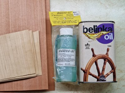
Today, all the packages arrived. I received: Patina-It, tung oil, and pink pear veneer. Additionally, I was given some alder veneer. It turns out that my decks are covered with alder. I thought it was pear wood. Although, it could still be pear, as alder resembles it. In any case, I now have material for deck samples and oil to carry out experiments. I've already tried linseed and teak oil, and now it's time for tung oil. As for Patina-It, I waited for it from America for two weeks. I can’t wait to coat a sample of the copper plating with it. Oh... more experiments ahead!

3D - 01
I understand that not everyone is optimistic about 3D technologies and may argue that traditional wood and metal are irreplaceable. However, for me, this hobby is about enjoying the process. I find it fascinating to design, print, and paint parts to resemble painted wood.
Don't get me wrong—I might have crafted everything from wood and metal if it were feasible. But at this scale and level of detail, achieving such results without specialized tools and ample time is unrealistic. That’s why I’ve decided to create a unique section where I track the number of custom-designed and printed parts, showcasing progress with a standardized template. I’ll start not with my earliest creations but as they are integrated into the hull, keeping a running tally. Let’s see how many parts this ship will ultimately feature made from the "much-criticized plastic."))))
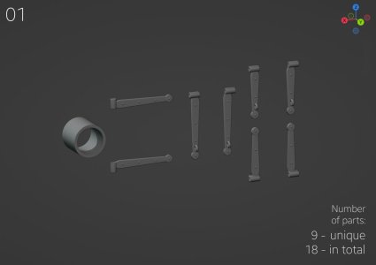
The first parts that were attached were the hinges for the gunport lids beneath the stern, followed by the hinges on the beakhead and the toilet windows. The photos of these have already been shared, but as they say, this is for the record. The next parts to follow will be the gallery details.
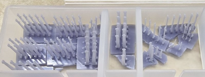
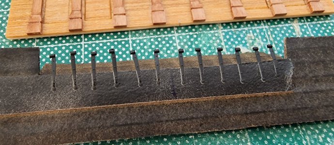
However, there will be one more section dedicated to 3D printing mistakes, similar to the previous one, and I think that will wrap up this topic. From there, it will solely be about manufacturing, painting, and assembly.
I understand that not everyone is optimistic about 3D technologies and may argue that traditional wood and metal are irreplaceable. However, for me, this hobby is about enjoying the process. I find it fascinating to design, print, and paint parts to resemble painted wood.
Don't get me wrong—I might have crafted everything from wood and metal if it were feasible. But at this scale and level of detail, achieving such results without specialized tools and ample time is unrealistic. That’s why I’ve decided to create a unique section where I track the number of custom-designed and printed parts, showcasing progress with a standardized template. I’ll start not with my earliest creations but as they are integrated into the hull, keeping a running tally. Let’s see how many parts this ship will ultimately feature made from the "much-criticized plastic."))))

The first parts that were attached were the hinges for the gunport lids beneath the stern, followed by the hinges on the beakhead and the toilet windows. The photos of these have already been shared, but as they say, this is for the record. The next parts to follow will be the gallery details.


However, there will be one more section dedicated to 3D printing mistakes, similar to the previous one, and I think that will wrap up this topic. From there, it will solely be about manufacturing, painting, and assembly.
- Joined
- Jun 17, 2021
- Messages
- 3,200
- Points
- 588

Hey, whatever works! These are enviable!
I have always been open to new technologies. If a part is under paint, I see no reason to be principled about what is under this paint))Good morning. Awesome post. I’m still learning 3D printing and have done some successful prints for my Xebec and Bounty. I have kept the printing to metal parts only (although on my Bounty I did the deadeyes) as I feel it does detract from the Authenticity on wooden parts. Brilliant hinges BTW. Cheers Grant
This is just the beginning, when I show the feed, many will think about it. I have almost finished it, I think I will post it in a few days.Hey, whatever works! These are enviable!
True storyThese are enviable!
Very interesting work with the 3D parts.
Can you explain a little to those of us with no 3D printing experience, how you get the parts into the 3D software?
Which software do you use?
How do you ensure scale?
What machine do you use to print, what settings and what material?
I noticed that some of the heart blocks did not have channels to allow for the rigging thread, and I appreciate that you go to some lengths to highlight that your post was about your learning curve and mistakes made, but will successful dead eyes, blocks and hearts need drilling to make them useful?
Thank you Sergey for sharing your knowledge, it is very appreciated.
Michael
Oh, these are very good questions! I have briefly covered some of the information, but I understand that it would be better to go into more detail about your questions. I think I will create a post with answers and illustrations and I will tag you so that you do not miss it. Thank you for your interest!Very interesting work with the 3D parts.
Can you explain a little to those of us with no 3D printing experience, how you get the parts into the 3D software?
Which software do you use?
How do you ensure scale?
What machine do you use to print, what settings and what material?
I noticed that some of the heart blocks did not have channels to allow for the rigging thread, and I appreciate that you go to some lengths to highlight that your post was about your learning curve and mistakes made, but will successful dead eyes, blocks and hearts need drilling to make them useful?
Thank you Sergey for sharing your knowledge, it is very appreciated.
Michael
True story
Such a remarkable process and post on innovative thinking. Please tag me on the 3D printing post.Oh, these are very good questions! I have briefly covered some of the information, but I understand that it would be better to go into more detail about your questions. I think I will create a post with answers and illustrations and I will tag you so that you do not miss it. Thank you for your interest!


