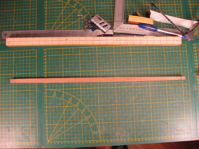
By the way, the drawings in the book are not accurate. There a major mistakes in the waterlines and in the bulkheads. The distance between the waterlines are not equal and the bulk head 17 is drawn 2 times and also different from each other.
Thanks for visiting my log and all the likes.
There is something I want to highlight in my log. The problems I found in the drawing that came with the book.
When you start drafting ship plans in CAD you soon notice that things can be inaccuraat. CAD is a very precise program to use and can be accurate to 0,0001 mm. An accuracy you don't need in your model, but the program uses this.
I can explain how things are done but here (
LINK) you can find a nice pdf on NRG how it's done.
Don't expect that your first attempts will be perfect. You discover more and more when you do this the first time. How the best way to drafting the lines of the plans in CAD, but also the function of all these lines in the drawing.
So after my first 2 attempts I discovered that the waterlines and the station lines (the vertical lines on the half breadth plan, on a right angle of 90 degrees on the waterlines) These terms you can find back in the document I mentioned before. The half breadth plan is the view on the top of the ship at different levels of the waterlines, the body plan is the view on the stern or bow. Back to my drawing, I discovered that the waterlines and station lines on my plan don't have the same distance of each other. This was the first inaccurate point in the drawings. After I made sure that the drawing in CAD have the right format (You can make your drawing in 1/1 scale, what I also did). I measure the distance between the fist station line on the stern to the last on the bow. That distance I divide by the numbers of lines after the first. After that you got the distance between every line of your plan. I did the same to the waterlines of the body plan.
I got 2 drawings after doing this and drafting the lines of the plan
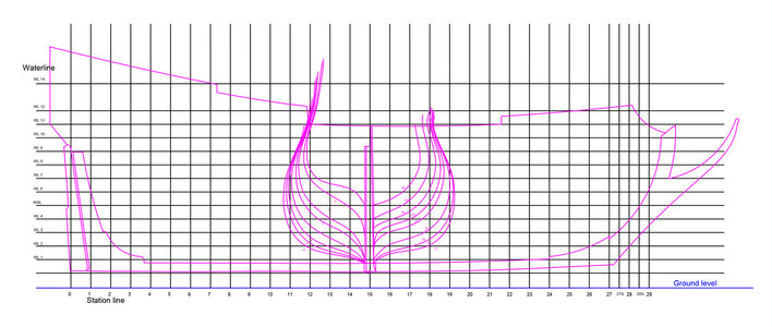

The second mistake I discovered was made in de station lines. Line 17 was on both side drawn and both where different
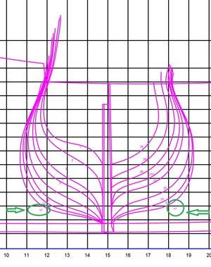
I had to find out what is going on here en decided to leave these open in my drawing of the single parts.
I made from each curved waterline and every curved bodyline a single drawing like it is till now. What would look like this:

For example I took Waterline 7 (left) and station line 7 (right) Distance A should be in both drawings be the same. This wasn't always the case. The third mistake in the drawing. I had to filter out these mistakes and make a new drawing that would be the perfect middle ground between the two would be. So I made 2 new sets of drawings. 1 new waterlines drawing out of the data of the original station lines and vice versa. And when this was done, I lay the drawings over each other and look where the difference where between them. I corrected the whole thing to a smooth line that was between the two.
The end result I put together in a 3D drawing.
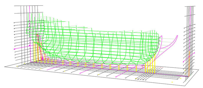
With the function orbit you can look around your model. And find all the spots that don't look right in your eyes. just by looking slowly from all angles you see mistakes in lines that don't fit to the lines next to it. You need to correct thes line in the 2D drawings and try again in 3D till it looks perfect and like a smooth hull. For me was this the way to do it. Maybe there are programs they can do this for you or there are commands in CAD that can do this. Let the experts correct me. But it works in this way and I was happy. (And it kept me off the streets because of the huge amount of work it required) I also filtered out the mistake of the names of the frames in this way. I discovered that the line 17 on the right side was correct and the left 17 was something around 15. Actually it didn't fit anywhere so I decided to cancel that line.
So far about these corrections.
I found out in the log of
@Olympic1911 that the first 3 frames not correspondent with the pictures of the ship. I did ignore this mistake because of the scale where I would build in. But that doesn't mean that I didn't checked it. Actually the difference between the drawing and the picture was more and less filtered out by the corrections I dit in the drawing. The difference was still there but a lot less.
Thanks for your visit and time to read this heavy stuff.


