• Win a Free Custom Engraved Brass Coin!!!
    As a way to introduce our brass coins to the community, we will raffle off a free coin during the month of August. Follow link ABOVE for instructions for entering.

I present to you the first published pages of the Pirate Ship document.

I think you might be surprised at how low the ceiling height was below deck on many ships of that time period.
For a crew walking the worst case is from the deck surface to the under side of the beams above which are shown on the drawings. The height between the bottom of the deck beam above and the surface of the deck below varied. Below are two fifty gun ships, Litchfield 1695 and Portland 1770 with the dimensions on the various decks. In the Portland drawing the legend at the top gives the distance from the beam on of the QD to the top of the beams of the round house. (Underlined portion) Both drawings were scaled to 1:1 then the measurements taken.
Allan
1743180302610.png
 
Hi UVS
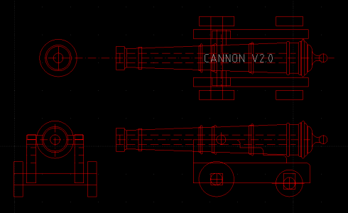
As you are still in the drawing stages are you open to changing anything? Some things in your drawings are very different than actual construction practice on the ships and contemporary models such as the joints of the keel, cannon pattern and carriage pattern.
Cheers
Allan
I would consider anything anyone points out, however I am not drawing this to be completely historic or authentic. I've tried to adopted different joints and ways of fastening things with more modern connectors, and criteria in woodworking that a regular joe could conveiveably do in a small woodworking shop, by limiting the overall sizes of the lumber they would easily be able to work with and sizes for each piece which would not be too expensive or rare to find. Large timbers are expensive and not as available as smaller pieces. Steel bolts and connectors, plates, etc is much easier to produce and buy off the shelf than back then when they had to manufacture everything in forges. I pretty much know every aspect of both woodworking and machining, so I am trying to basically make a hybrid design of old techniques and new ones. I am not so closed minded to look at something and say "hey that is a reasonable and meaningful or more efficient design"
 
For a crew walking the worst case is from the deck surface to the under side of the beams above which are shown on the drawings. The height between the bottom of the deck beam above and the surface of the deck below varied. Below are two fifty gun ships, Litchfield 1695 and Portland 1770 with the dimensions on the various decks. In the Portland drawing the legend at the top gives the distance from the beam on of the QD to the top of the beams of the round house. (Underlined portion) Both drawings were scaled to 1:1 then the measurements taken.
Allan
View attachment 510436
I would hate to be the poor soul who served on that ship. Can you imagine the work on decks with low headroom all the time? You would have to hunch over to walk to and fro, and after hours of this I am sure your body would be sore.
 
I would hate to be the poor soul who served on that ship. Can you imagine the work on decks with low headroom all the time? You would have to hunch over to walk to and fro, and after hours of this I am sure your body would be sore.
Remember, in those days, people from north western nations were a lot shorter due to poor nutrition. This is not the case anymore. Better nutrition.

Marcus
 
As a retired machine designer I can appreciate the work you are putting in these drawings Well done
Thanks so much for your kudos. I have removed myself from posting pictures, and using 2D CAD to design all the ship. It is well under way. My estimate is that 50% of all the pieces are drawn in CAD.
 
Hi UVSaturated
The only metal I have cast into cannon is pewter. Casting bronze could be interesting but I will probably stay with making a master with a lathe then making a mold and casting in resin rather than bronze or having 3D printed guns from my collection of drawings for various eras and nationalities.

Your drawings are very interesting but I hope you don't mind me asking why you are not making the designs as they were actually done on a ship?

The reason is because I am designing a ship based on the Walt Disney movies, the 'Black Pearl'. Now, the ship in the movie is not practical. I can tell you that because I am reverse engineering it on CAD. I am not trying to replicate historically what was done, but making a new ship with old school advices. I gather information here by you peoples posts, and that helps me in understanding the nature of the craft, but why it was designed the way it is. For example, the seat of ease was placed at the head of the ship. Why? Mainly because of crew politics. The executives, the Captain and his administrators had their own seat of ease seperate from the crew. I am understanding Naval terms like port and starboard. Most people do not know the meanings of those words, or the light beacons on an aircraft that is red or green. They use the same protocols on ships so that a vessel can be determined from afar if it is coming or going away from the ships vantage point.

I am not trying to duplicate or authenticate historical vessels, or armament. The cannon drawings though do impress upon me as I know a lot about casting and machining.

midship.png

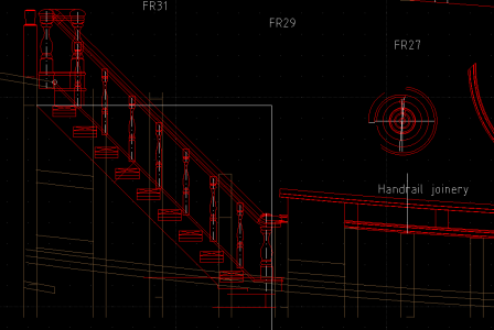
handrails.png

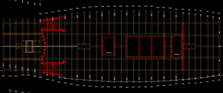
main deck.png
 
Here is the latest on this project so far. It has been a long time since I have posted to this thread, and here are it's updates:

I had to rethink the way I was proceeding with the illustration work as I found compiling mathematical errors in the just the Keel and the Bow, and it took me some time to reevalute my methodology in producing the blueprints. I have spent about a year and a half now on it and still cooking! I used to have 3D CAD but have resorted to 2D CAD which is sufficient with my limited resources. So with the CAD work on the Pirate Ship I am about 65% in completion of the basic structure and uniformity across the frames of the ship. I had to rescale the ship also because I saw that the size would not work full scale which I had intended. The truth is, I am going to produce free CAD drawings for the pirate ship for hobbyist to build at any scale, and the original 1:1 scale prints I am engineering for sale at boat and marine shows. You know that rich kids love to spend money at those? Here's to flying the Jolly Roger.

Let me educate you.png

Basic Cannon.png

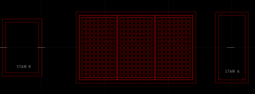
cargo hold with two staircase openings.png

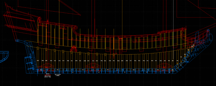
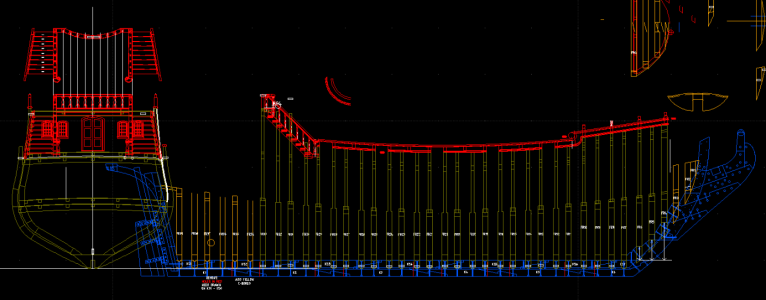
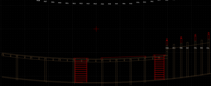
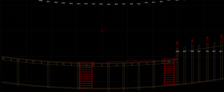
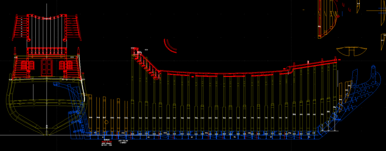
Elevation with frames 1-35.png

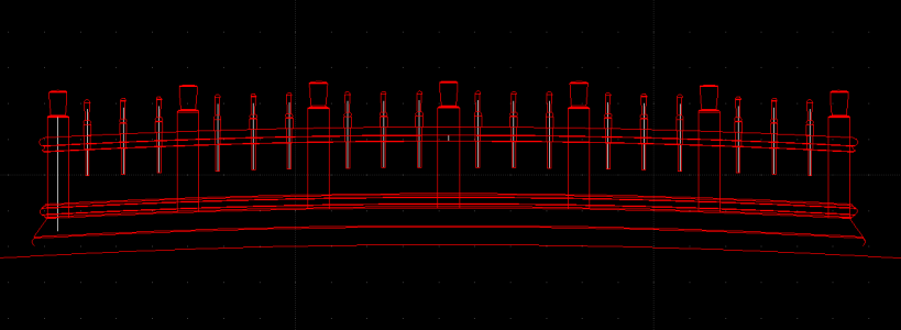
Railing B.png

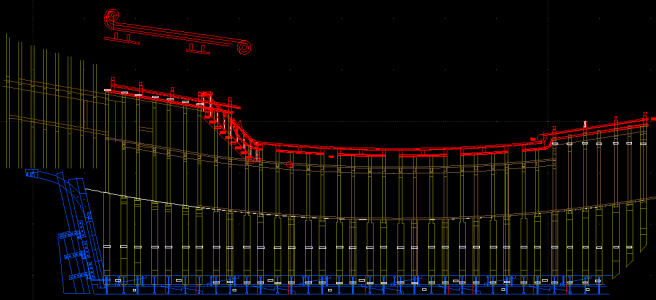
elevation view of main deck and gun deck with some stairs and whatnot.png

frames 4-9 of fore deck.png

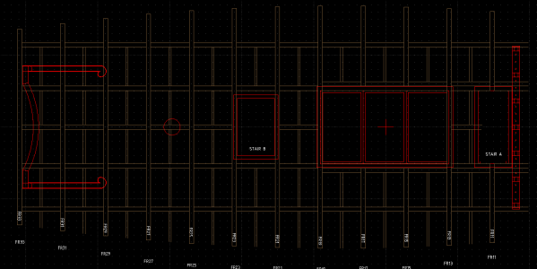
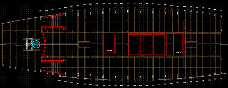
Maindeck structure planview.png

elevation view of main deck and gun deck with some stairs and whatnot.png

Elevation with frames 1-35.png
 
I've got to a break from this for a month or so right now though. I am filing a lawsuit against my apartment managment and doing a new piece of digital artwork for therapy. Be back a few folks.
 
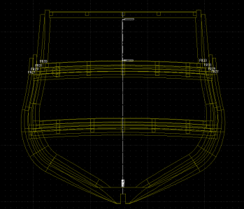
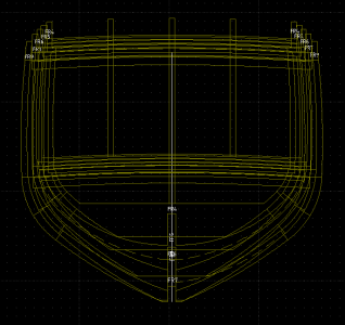
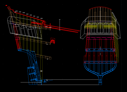
Working on the stern now. Truthfully, designing the components for the stern section has been the most challenging part of the design. Almost everything is curved, and pieces are running at different angles. Mind you I am using 2D CAD so anything I draw I use the age old process of using projections to figure out the different views. (edit: The white vertical stick in the middle represents the height of a 6 foot tall person.)

STERN.png
 
This is quite amazing work. I want to learn more about LibreCAD now. I'm wondering if you are planning to release the drawing itself in LibreCAD format. Regardless, you decision to share your work in this post is very appreciated.
 
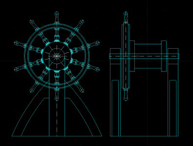
I completely get that this is a fantasy vessel but as your pirate ship design is for a ship of the 17th century keep in mind steering wheels were not used. The earliest wheels appeared after the turn into the 18th century and was not common until after about 1711. Prior to the introduction of the wheel the steering was done using a tiller just like on a small boat.
Allan
Well, I would not say it's a 17th century ship, but an 18th century ship. From the Pirates franchise movies though, I think the era depicted was probably the mid to late 1700's. (1750-1800). That is just my guess based on the fact that in the movie the British are in period Red Coats and depict the pirates main government adversary. It is what it is though. If you have ever been to any of the Disney theme parks you will understand they are experts at making you believe something that is a total fantasy is actually real. Take Cinderella's Castle, a giant fiberglass structure, but to the uninformed it looks like its made of real stone.
 
This is quite amazing work. I want to learn more about LibreCAD now. I'm wondering if you are planning to release the drawing itself in LibreCAD format. Regardless, you decision to share your work in this post is very appreciated.
My plans are to release two versions, one for sale and the other for hobbyists. The hobby version will be free, but the version for sale will include technical details that you would really not need to build the ship as a model. I will try to get this done soon, however I am starting to believe that if I don't get my hands on some 3D CAD software soon, it's gonna still take quite a while. It's very difficult to visualize a 3D surface from photographs and transfer that to 3 view drawings, especially in areas of the hull where the curves are more dramatic. There is no landmarks visually to figure out a linear distance when something is curving in two directions. Back to the original topic in your statement though, yes I will try to publish drawings that are in .dwg format.
 
Here is an example of why 3D CAD is a lot more suited to drawing ship hulls. During my process, when I get tired of the monotony of working on one thing, I switch to some other part of the drawing that needs addressed. I have noticed that after resolving to quit drinking alcohol (a month and counting), the precision of my CAD work is a lot better. There were definitely some nights that I made some dire mistakes on the drawing, only to come back and re-correct my work. What this amounts to in error checking is that your lines in CAD, have to "snap" to certain points on other lines. If you are in a hurry and are careless or maybe a little too drunk you can snap on another line that is close by mistake and end up compounding errors. Of course, in sobriety you find your mistakes and it makes it all so obvious how the quality of your work is much better without drinking.

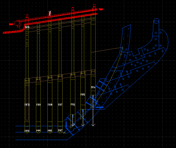
Now that I got that off my chest, I was gonna show you all what I am up against currently. I switched back to working on the bow section of the ship, which I had not worked on in over a year now. When I returned to that portion of the ship, I immediately error checked all the locations of the components and looked closely at the accuracy of where each component crossed another in geometry. Here is the product of that. The dark green lines represent the starboard elevation of the bow with the frames labelled 4-10 anchored to the keel to the bottom and also beginning to be anchored into the bow section. The brown lines represent the centerline of the decks crossing frames 4-10, and the red lines are the railings and adornments.

bow1.png
 
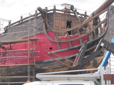
The above elevations looks okay until you study a real picture of the ships hull. It would be nice to have pictures that are taken perpendicular to the hull, but I don't have the luxury to travel to California or Hawaii or wherever this vessel is berthed now to take my own pics. These were probably taken a good decade ago. Anyway, some obvious things I missed is that the number of stantions on the left add up to 4 and the ones on the right add up to 5, yet it looks as if the distance on across the 5 stantions are shorter than the 4 to the left. In the next picture I will show you this HUGE error that I have to fix.

bow3.png
 
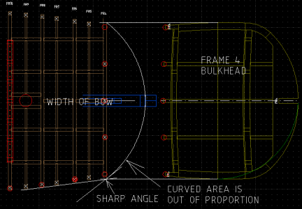
In this view from the top of the same previous image you see where the problem lies. In the CAD drawing all the stantions (post railings) are cicrcled in red. There are 5 in front and 4 on either side. Now if you look at the linear distances you quickly see that in the CAD drawing the front is longer than the side, which is just the opposite in the image above from the picture. That is why this small area in front of frame 4 is all crunched up to a distance of about 70" deep and 280" wide. So with my new found knowledge of a really crappy error, I took the photo above, which does not lie and traced it in CAD. By using some extrapolation to account for the two different places you work with you can figure out using scaling and percentages what the proportions should be. I hope to fix this in a week or so.

bow2.png
 
Last edited:
Back
Top