This is very educational, Paul. Men doing this in the real world, back in the day.... mind blowing!
You are using an out of date browser. It may not display this or other websites correctly.
You should upgrade or use an alternative browser.
You should upgrade or use an alternative browser.
Kingfisher 1770 1:48 POF
- Thread starter dockattner
- Start date
- Watchers 136
- Joined
- Aug 8, 2019
- Messages
- 4,835
- Points
- 688

But they just didn't use such large sheets of glassThis is very educational, Paul. Men doing this in the real world, back in the day.... mind blowing!

As always, I am grateful for your guidance Christian.Paul,
my experience with double sided tape is not as good as with rubber cement (for example Marabu Fixogum). The adhesive of the tape is mostly to strong, and is not as easy to remove it from the frames.
Make yourself two copies of the DoF Plan and give each frames a number. Now you can mark each frame which you have prepared at the plan and write the number with a pencil on the frame. (I use the number of the station lines followed by a small a (after) or f (fore) for this task). I doN't know if the kit uses a jig. If not I can only recommend to prepare one.
Your proces is lookinge very well structured. I wish you a lot of meditative hours building all the frames of the sloop.
The frame design is in this detail simplified (what is for the scale of your model absolut fine). At the original ship it's more complicated, but you can show this only at 1/36 or another bigger scale.
There are two fully shifted timbers also in the original drawing of Cygnet. They are build wrong at the beautyful model Dean shared with us. The thickness of the futtocks is given by the dimenison. The problem at this model is that the chocks are not build correctly. The width of the chock has to be the whole with of both frames.
I should have spoken more precisely: I am using double-sided tape designed for posters - it has a mild adhesion and is easy to peel off.
I will follow your advice for labeling the frames - thank you! And, yes, the kit comes with the pieces for fabricating a building jig. Ted shows it in his build report with some upgrades for rigidity which I will be attempting to duplicate.
I don't think I am tracking with you when you say, "The width of the chock has to be the whole width of both frames." On the plans I have from LSS the frames with the offset top timbers appear to have the chocks trimmed as shown in Bob's prototype model. Or are you referring to something in the pictures of Ricci's model?
I will say that the offset frames appear weak at the offset...
- Joined
- Oct 23, 2018
- Messages
- 696
- Points
- 353

Hi Paul,
I've just been downstairs to look at my own model of Kingfisher (from LSS - the same as your kit)
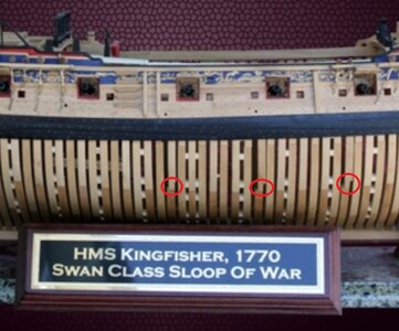
The three joints highlighted by Christian are the same on my model, and occur where the frames behind gunports 2,3 and 4 have been 'shifted' forward to allow the frame extension to become the rear timber of the port. I don't know whether this is a mistake, but I wouldn't loose any sleep over it - it doesn't stand out on the model! See picture below.
In regard to sanding the scarphs - don't.
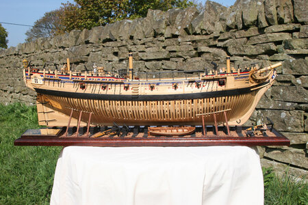
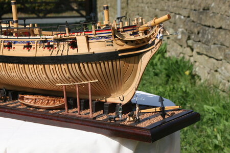
I thought I hadn't any pics of the area in question, but have just found this one - you can see the joints just behind gunports 2 and 3. (suggest blow the image up)
Ted
I've just been downstairs to look at my own model of Kingfisher (from LSS - the same as your kit)
The three joints highlighted by Christian are the same on my model, and occur where the frames behind gunports 2,3 and 4 have been 'shifted' forward to allow the frame extension to become the rear timber of the port. I don't know whether this is a mistake, but I wouldn't loose any sleep over it - it doesn't stand out on the model! See picture below.
In regard to sanding the scarphs - don't.


I thought I hadn't any pics of the area in question, but have just found this one - you can see the joints just behind gunports 2 and 3. (suggest blow the image up)
Ted
Last edited:
- Joined
- Oct 15, 2017
- Messages
- 1,038
- Points
- 443

Just catching up Paul. Again, your work reaches a standard I will not realize for some time, if ever. I too think better in metric terms. As an American, I cannot come to understand just why. My best friend is a retired machinist, who owned his own company. When I relate to him what I've done on my ship and express it in metric terms, he immediately converts it into imperial decimal terms. He is a walking, talking conversion table. Now if I could get him to sit next to me on my work bench.....alas. To add to the conversion complexity, the current monograph I'm using is in real imperial terms, but using the French foot, which is not 12 in/ft.Thank you kindly, gentlemen, for the encouraging posts and likes. I've decided to refine the tapering a bit more in order to get me closer to the build requirements found in TFFM.
A passing observation from my experience using this series of books thus far: the measurements provided in the text are generally given full-size and in the imperial system. For example, for the stern deadwood I am told to make the width at the bearding line (basically where you see the notched area for the frames to seat into) 15 inches and then taper down to 5 inches at the bottom where the deadwood joins the keel.
By using actual measurements from a full-sized ship this allows the book series to accommodate every modeler's preferred scale. Makes perfect sense, right?
Well, this creates all sorts of tripping-up points for me because I think in metric (Why, you ask? Because I can picture 2.6 mm in my mind but not .104 inches). This means I need to first convert inches into mm and then adjust for my scale (1:48). Of course, the math isn't hard, but it all introduces room for mistakes to be made. I find myself constantly checking and recalculating things over and over again. I can't tell you how many times I've said to myself: how can you be so dumb?
When my dad was frustrated with me he used to say, "you've the dumbest smart kid I ever met." I didn't like that very much - but it seems he may have been right.
- Joined
- Oct 15, 2017
- Messages
- 1,038
- Points
- 443

As I'm posting as I read, I'm not sure if anyone has suggested this or not, yet. Is there a way for you to prepare the wing transom and dry fit to give you a better visual as to how the transition from stern post to wing transom will look/happen, assuming the wing transom will also have a rabbit where the planks transition from the stern post to transom? Sorry for the long sentence. I may have to download that app, Grammarly(sp).Work continues on the aft centerline...
View attachment 354104
View attachment 354105
View attachment 354106
The precision required is beginning to concern me. I have been having a hard time committing to the work out of concern that I'm messing something up now that won't be easy to fix later. I find myself thinking: I guess that's right more often than I would prefer...
It seemed best to only partially finish the rabbet at the upper sternpost at this stage. I assume I will be able to refine it later when the transom pieces are fabricated and test-fitted.
I'll say this much: POF construction is quite a challenge in terms of figuring out WHAT to do - as well as the actual DOING. I have a deeper respect (awe) for some of the work I see on this forum than I had before beginning this build.
Here in the UK, we converted from Imperial to Metric in the sixties, just when I was studying civil engineering at college. Hence I had a very good grounding in both systems. At exam time we were given the questions in both imperial and metric, and could use either as we wished.
Nowadays, I just use whichever system is most convenient for the job in hand and convert in my mind if necessary.
Later, when I was running construction sites, I had a venerable old joiner on one occasion who told me a certain measurement he had taken was 'three feet and seventeen centimetres' Ah well, you can't win them all!
Ted
- Joined
- Oct 15, 2017
- Messages
- 1,038
- Points
- 443

Some double sided tape is made specifically for wood working. It is "low tack" and leaves no residue on the wood, while maintaining a very good temporary adhesion. I found such tape on Amazon.Paul,
my experience with double sided tape is not as good as with rubber cement (for example Marabu Fixogum). The adhesive of the tape is mostly to strong, and is not as easy to remove it from the frames.
Make yourself two copies of the DoF Plan and give each frames a number. Now you can mark each frame which you have prepared at the plan and write the number with a pencil on the frame. (I use the number of the station lines followed by a small a (after) or f (fore) for this task). I doN't know if the kit uses a jig. If not I can only recommend to prepare one.
Your proces is lookinge very well structured. I wish you a lot of meditative hours building all the frames of the sloop.
The frame design is in this detail simplified (what is for the scale of your model absolut fine). At the original ship it's more complicated, but you can show this only at 1/36 or another bigger scale.
There are two fully shifted timbers also in the original drawing of Cygnet. They are build wrong at the beautyful model Dean shared with us. The thickness of the futtocks is given by the dimenison. The problem at this model is that the chocks are not build correctly. The width of the chock has to be the whole with of both frames.
QUESTION to Admins: I use to post Amazon links that would result in the neat dialog box and not the actual URL. For some reason recently my links display as the actual URL and not the pretty box. Can anyone direct me as to how I can resolve this and avoid ugly URLs.
- Joined
- Oct 23, 2018
- Messages
- 696
- Points
- 353

Paul,
I found the reason for the small mistake. LSS did not use a regular chock. The easiest way to avoid this, is to glue a small and thin piece of timber at the side of the chock and don't cut the third futtock.
@tedboat
Your model is looking really good. I love the color of the boxwood. Was the small cutter model also in the kit? Can you share some more pictures with us?
Yes, this is exactly what I will do. Thank you.As I'm posting as I read, I'm not sure if anyone has suggested this or not, yet. Is there a way for you to prepare the wing transom and dry fit to give you a better visual as to how the transition from stern post to wing transom will look/happen, assuming the wing transom will also have a rabbit where the planks transition from the stern post to transom? Sorry for the long sentence. I may have to download that app, Grammarly(sp).
Hi Paul, Bob Hunt here. Thought I'd chime in to thank you for the compliment on my kit design. I worked very closely with David Antscherl and Greg Herbert when I designed the kit. I used David's drawings with his permission and also paid him a royalty for every kit I sold. Greg Herbert and I go way back. He provided me with every photo he took when he built the prototype. I attended some special classes with him and David at his house in Maryland and took my prototype model for the class attendees to see.This piece (stern deadwood) was almost the end of me: tapered top to bottom and also front to back - and then notched to receive the aft cant frames. But the kit design made this something even a relative newcomer could accomplish with careful chisel work and sanding blocks. Well done, LSS and Mr. Hunt.
View attachment 353124
View attachment 353125
View attachment 353126
View attachment 353127
The top to bottom taper should be more concave but I'm hoping this will still work. Thanks for stopping by!
As you can tell, I used a layering techniques to make easier to build. Those steps for the cant frames on the stern deadwood and the bow inner deadwood are just one example. Once assembled, it looks like it's a part of the deadwood. As a matter of fact, if you look closely at the various parts to the stern deadwood outer layer, they match the inner thick layer so that it looks like it's all one single piece of wood.
The kit required over 2000 CNC milled parts and it took 4 days running one mill 8 hours a day to cut all of those parts out. I had two Shopbot router mills so I was able to produce 2 kits in a week but because I was also producing 3 other kits, the Fair American, the Halifax, and the HMY Fubbs, each kit only got produce once per month. The Kingfisher was the most popular I ever designed and produced by myself and I was always 6 months behind in production.
Alas all good things must come to an end so eventually my wood supplier retired and I had to shut the kit part of my business, The Lauck Street Shipyard, down. However the practicum part is still going and I will celebrate 20 years in business on June 1st. My website is https://www.lauckstreetshipyard.com . I also write articles for the Model Shipbuilder Journal over at the MSB forum owned by Winston Scoville.
Just thought everyone might want a little bit of production history on this kit. I'm please to see you building the kit and compliment you on the fine job you're doing so far. If you have any questions for me, just give me a shout.
Bob Hunt
Tobias is correct. I can't recall what my reasoning was for the "U" shape of the rabbet at that area, perhaps just a senior moment or brain fart but if you think about it, the planking is coming around the side of the ship so it stands to reason it would fit best with a "V" shaped rabbet join in that area. No one said historically correct ship modeling from scratch or designing a kit of such complexity is easyHello Paul I think you are referring to the area marked with the red arrow. In the Ancre monographs this area is also always V-shaped and not semicircular. I think it should be V-shaped because your planks are also at right angles at the end and not rounded to create a clean transition. You also have this at the bow. See pictures.
View attachment 353821
View attachment 353822
View attachment 353823
Bob
Hi Paul,
I've been through your entire build log and from what I've seen, you haven't made any mistakes. It is true that my chocks are not as David Antscherl's book shows. I felt that the average person building the kit would have difficulty making those historically correct chocks so I went for the simpler type that do not have angled or beveled surfaces at the joint.
I've learned over the years that designing a kit requires some compromises because you have to consider the customer who might buy your kit and what his or her skills are like. Not everyone can do a perfect job, including myself. So I made such compromises because I felt it was necessary. I would rather see every customer actually finish the model than to see them butcher it and end up throwing it away or using it for firewood. After all, it was probably the most expensive kit on the market at the time I was producing it. So my goal was to design it with the hopes and intentions of making it as easy as possible to build given the complexity of the subject ship while trying to maintain as much historical accuracy as possible. I'm not making excuses, I'm just trying to explain what's involved in designing a kit. I challenge anyone who might have a problem with the compromises I made to design the exact same model using the exact same plans and drawings without such compromises. At that time, 3D milling was not even an option because the technology had not reached that level (the available CAM software).
Anyway, keep up the excellent work. I'll try to follow along as you progress. If you have any questions you can also reach me on my website using my Contact page.
Take care,
Bob Hunt
Thanks for stopping by Bob. There aren't too many build reports on this kit and I consider it a real privilege to be able to share your production work with the members of our forum. My guess is there are very few of these kits left anymore...Hi Paul, Bob Hunt here. Thought I'd chime in to thank you for the compliment on my kit design. I worked very closely with David Antscherl and Greg Herbert when I designed the kit. I used David's drawings with his permission and also paid him a royalty for every kit I sold. Greg Herbert and I go way back. He provided me with every photo he took when he built the prototype. I attended some special classes with him and David at his house in Maryland and took my prototype model for the class attendees to see.
As you can tell, I used a layering techniques to make easier to build. Those steps for the cant frames on the stern deadwood and the bow inner deadwood are just one example. Once assembled, it looks like it's a part of the deadwood. As a matter of fact, if you look closely at the various parts to the stern deadwood outer layer, they match the inner thick layer so that it looks like it's all one single piece of wood.
The kit required over 2000 CNC milled parts and it took 4 days running one mill 8 hours a day to cut all of those parts out. I had two Shopbot router mills so I was able to produce 2 kits in a week but because I was also producing 3 other kits, the Fair American, the Halifax, and the HMY Fubbs, each kit only got produce once per month. The Kingfisher was the most popular I ever designed and produced by myself and I was always 6 months behind in production.
Alas all good things must come to an end so eventually my wood supplier retired and I had to shut the kit part of my business, The Lauck Street Shipyard, down. However the practicum part is still going and I will celebrate 20 years in business on June 1st. My website is https://www.lauckstreetshipyard.com . I also write articles for the Model Shipbuilder Journal over at the MSB forum owned by Winston Scoville.
Just thought everyone might want a little bit of production history on this kit. I'm please to see you building the kit and compliment you on the fine job you're doing so far. If you have any questions for me, just give me a shout.
Bob Hunt
I'm not an experienced model builder but I will give this my very best effort. I'm sure I'll make some changes along the way (for example, I intend to simulate the chocks in the framing - or at least I think I will - still need to figure out how visible they are). Depending on how things are going I might add in some additional detailing though none of that is determined as of yet.
I am blessed to have some more experienced builders looking over my shoulder and will reach out to you if I encounter something unique to the kit I just can't figure out.
Last edited:
GREAT EXPLANATION BOB. GOD BLESS STAY SAFE YOU AND YOURS DON
Looking fabulous, Paul!
Kurt Konrath
Kurt Konrath
Doc K. You say your not an experienced builder, but I have to disagree with you.
You may have only one major build and the scratch built small boat, but the level and exactness of your work cries out to your experience.
It is not the number of ships built alone that make a person experienced.
Keep up the great work and I will be watching along with the crowd around the workshop.
The other Kurt
Gentlemen (and Ladies?),
I have had lots (translation: LOTS!) of modeling time since my last posting, during which I have dedicated myself to fabricating square frames (since they are not in fact square, I assume this refers to their orientation to the keel - that is, they mount 90 degrees to the run of the keel). I thought these would be the easiest place to start and I believe this has been borne out.
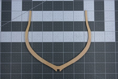
The frames are paired at each station. One frame has a cross chock at the keel and the other frame has floors. The example above shows a frame with floors.
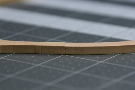
As I mentioned previously, the frame elements get smaller as they move up (away from the keel). I have been careful to preserve this historical element as I have been sanding the fore and aft faces of each of these frames:
I won't always have as much hobby time going forward so this is going to take a while...
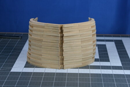
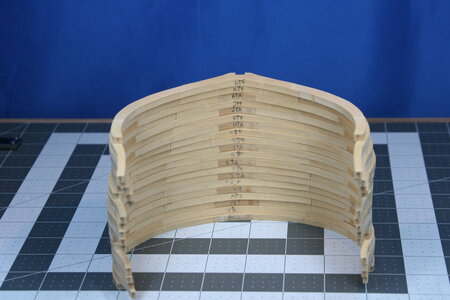
I have some stepped up work and teaching responsibilities in the weeks ahead (I'm NOT teaching how to build a model ship ), so when I get back to the shipyard I might just continue making more of these, or try my hand at some of the more difficult frames.
Thanks to everyone who offered tips and advice recently - and thanks for the likes as well!
I have had lots (translation: LOTS!) of modeling time since my last posting, during which I have dedicated myself to fabricating square frames (since they are not in fact square, I assume this refers to their orientation to the keel - that is, they mount 90 degrees to the run of the keel). I thought these would be the easiest place to start and I believe this has been borne out.

The frames are paired at each station. One frame has a cross chock at the keel and the other frame has floors. The example above shows a frame with floors.
As I mentioned previously, the frame elements get smaller as they move up (away from the keel). I have been careful to preserve this historical element as I have been sanding the fore and aft faces of each of these frames:

I won't always have as much hobby time going forward so this is going to take a while...


I have some stepped up work and teaching responsibilities in the weeks ahead (I'm NOT teaching how to build a model ship
 ), so when I get back to the shipyard I might just continue making more of these, or try my hand at some of the more difficult frames.
Thanks to everyone who offered tips and advice recently - and thanks for the likes as well!
Last edited:


