Looking good Paul. Those frame offsets are tricky business.

You are using an out of date browser. It may not display this or other websites correctly.
You should upgrade or use an alternative browser.
You should upgrade or use an alternative browser.
Kingfisher 1770 1:48 POF
- Thread starter dockattner
- Start date
- Watchers 136
- Joined
- Jan 9, 2020
- Messages
- 10,500
- Points
- 938

I hear you about the uncertainty thing - I would not have liked that either. However, I am sure that after all your research and checking up, you are on the right track. You might have to do some individual adjustments here and there, but as far as the bulk of the construction goes, I'm sure you will be fine!Work is slowly continuing on the square frames.
While the vast majority of them follow the same subtle stepping pattern (cross chocks, floors, and first futtocks are 10", second futtocks are 9 1/2", top timbers are 9" - all actual sizes) there are 6 frames that have 'offset' top timbers. Some of the offsets are small, but others are rather substantial.
In order to create the offset accurately it was simply a matter of custom fabricating spacers of the required thickness:
View attachment 359506
A closer look at the offset:
View attachment 359507
While I am able to split the thickness of the chocks for the normal 1/2" step that would create a very narrow overlap zone for these offset frames. To that end I inserted some faux chocks:
View attachment 359508
View attachment 359510
And now roughly shaped:
View attachment 359511
There is still some work to do here but my research has not yet revealed what to do with these offset areas now that I have the faux chocks in place...
There are also some special frames that have 'bent' top timbers (cast frames). On a scratch build these would simply be created from dimensional stock - but the kit uses a layering technique.
(Yesterday I received my order of boxwood so theoretically I could now build these cast frames from scratch - but I thought I would give the kit design a shot to see how it would look.)
Here is the addition of a layer of wood (about 2 mm at scale) on the forward side of one of the frames:
View attachment 359509
And now roughly shaped:
View attachment 359512
So far, so good.
Next, I'll need to remove the same amount of wood (2 mm) from the aft side to create the bend. I would show you that attempt but I'm working tomorrow morning and I have some preparations to complete so model building will have to wait for another day.
I hope I'm getting all these frames right! It's quite a lot of work without really knowing if things are being done properly...
Thank you for visiting!
- Joined
- Oct 23, 2018
- Messages
- 696
- Points
- 353

Perfect! Your solution is looking really good.
")

Good morning Paul….I guess you will find out sometime….I hope I'm getting all these frames right! It's quite a lot of work without really knowing if things are being done properly...
") . “My moneys on you Paul”.
. “My moneys on you Paul”.The frames and faux chokes look stunning tho. Cheers Grant

Good morning Paul, really impressive how clean you are. I know these curved frames from the Speedwell and Naiad drawings and yes they are a challenge to make. I can only agree with Christian that you have found a great solution for this.
You write that you got the wood, I think it was from Vahur, would you like to show a picture of what it looks like, I would be interested in the quality.
You write that you got the wood, I think it was from Vahur, would you like to show a picture of what it looks like, I would be interested in the quality.
- Joined
- Aug 8, 2019
- Messages
- 4,835
- Points
- 688

Nice solution that could be handy to my build. Thanks for showingIn order to create the offset accurately it was simply a matter of custom fabricating spacers of the required thickness:
- Joined
- Jul 9, 2019
- Messages
- 495
- Points
- 323

Laid out neat as toy soldiers. Looking good.
BTW, I just saw a Bob Hunt Kingfisher on eBay for $2,000. If only librarians were reimbursed a bit more equitably. . . .
Last edited:

Great work on the frames Paul. Very clean and informative for the watching crowd. Maybe in the far future it will win me over to the world of POF.
Second build, first PoF ….. and making offset frames so smooth and clean …… Impressive Paul.
Regards, Peter
Regards, Peter
Very impressive work on your frames amd the offsets Paul, there is a lot of learning to do for you, but in the meanwhile, we are learning a lot from you as well
- Joined
- Sep 3, 2021
- Messages
- 4,859
- Points
- 688
When you're not really sure about that offset, you could also take some pieces of scrap and run some tests to check what the best approach is and what yields the best, most authentic appearing results.Work is slowly continuing on the square frames.
While the vast majority of them follow the same subtle stepping pattern (cross chocks, floors, and first futtocks are 10", second futtocks are 9 1/2", top timbers are 9" - all actual sizes) there are 6 frames that have 'offset' top timbers. Some of the offsets are small, but others are rather substantial.
In order to create the offset accurately it was simply a matter of custom fabricating spacers of the required thickness:
View attachment 359506
A closer look at the offset:
View attachment 359507
While I am able to split the thickness of the chocks for the normal 1/2" step that would create a very narrow overlap zone for these offset frames. To that end I inserted some faux chocks:
View attachment 359508
View attachment 359510
And now roughly shaped:
View attachment 359511
There is still some work to do here but my research has not yet revealed what to do with these offset areas now that I have the faux chocks in place...
There are also some special frames that have 'bent' top timbers (cast frames). On a scratch build these would simply be created from dimensional stock - but the kit uses a layering technique.
(Yesterday I received my order of boxwood so theoretically I could now build these cast frames from scratch - but I thought I would give the kit design a shot to see how it would look.)
Here is the addition of a layer of wood (about 2 mm at scale) on the forward side of one of the frames:
View attachment 359509
And now roughly shaped:
View attachment 359512
So far, so good.
Next, I'll need to remove the same amount of wood (2 mm) from the aft side to create the bend. I would show you that attempt but I'm working tomorrow morning and I have some preparations to complete so model building will have to wait for another day.
I hope I'm getting all these frames right! It's quite a lot of work without really knowing if things are being done properly...
Thank you for visiting!
Thank you Bryian, Heinrich, Christian, Shota, Grant, Tobias, Peter, Stephan, Eric, Herman, Peter V, Peter (pingu), Johan and everyone else for the likes. I appreciate the encouragement!
Yes, from Vahur. The quality is fantastic. Give me a few days and I'll post some pictures. I'm still doing inventory and repackaging and I don't want to get lost.You write that you got the wood, I think it was from Vahur, would you like to show a picture of what it looks like, I would be interested in the quality.
I thought I should wrap up the documentation of the fabrication of the bend on my cast frames. I had previously added a 2mm strip on the forward side of the frame and I now needed to remove a 2mm strip from the aft side of that frame.
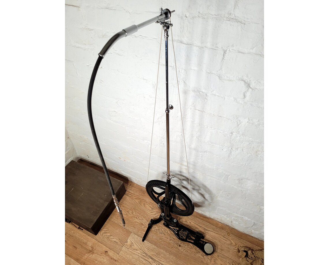
I considered several approaches ranging from just using files and sandpaper all the way to using my mill for the first time ever. In the end I used my disc sander but not before modifying it (@Steef66 would have made a new disc sander out of a bicycle wheel, the motor from a kitchen blender, and parts he ordered from Ali for just under 3 euro... but I lack his ingenuity).
I think the following photos will make my modification of the disc sander clear:


I now have access to the edge of the disc...
I marked out the portion I needed to remove:

And then carefully sanded back to the line checking over and over again for accuracy...

And this was the result:


I am currently sanding the fore and aft surfaces of the offset and cast frames and snapping joints out of carelessness. I decided it was best to stop for the day...
You are kind to follow my build!
I considered several approaches ranging from just using files and sandpaper all the way to using my mill for the first time ever. In the end I used my disc sander but not before modifying it (@Steef66 would have made a new disc sander out of a bicycle wheel, the motor from a kitchen blender, and parts he ordered from Ali for just under 3 euro... but I lack his ingenuity).
I think the following photos will make my modification of the disc sander clear:
I now have access to the edge of the disc...
I marked out the portion I needed to remove:
And then carefully sanded back to the line checking over and over again for accuracy...
And this was the result:
I am currently sanding the fore and aft surfaces of the offset and cast frames and snapping joints out of carelessness. I decided it was best to stop for the day...
You are kind to follow my build!
- Joined
- Aug 8, 2019
- Messages
- 4,835
- Points
- 688
(@Steef66 would have made a new disc sander out of a bicycle wheel, the motor from a kitchen blender, and parts he ordered from Ali for just under 3 euro... but I lack his ingenuity).
 no, things like that I would sand by hand. Those machines are to heavy for such a delicate job. Something I learned by experience.
But if you want I can make you plans how to build such a tool.

I don't think he would need one, Steph. When he graduated from dentistry school he was awarded the tool he is using today as part of his job and hobby as wellBut if you want I can make you plans how to build such a tool.
- Joined
- Sep 3, 2021
- Messages
- 4,859
- Points
- 688
Snapping and frames, those two words, used in on sentence, spell small disasters. For your consolation, I've seen my fair share of those, despite my efforts to avoid them.I thought I should wrap up the documentation of the fabrication of the bend on my cast frames. I had previously added a 2mm strip on the forward side of the frame and I now needed to remove a 2mm strip from the aft side of that frame.
I considered several approaches ranging from just using files and sandpaper all the way to using my mill for the first time ever. In the end I used my disc sander but not before modifying it (@Steef66 would have made a new disc sander out of a bicycle wheel, the motor from a kitchen blender, and parts he ordered from Ali for just under 3 euro... but I lack his ingenuity).
I think the following photos will make my modification of the disc sander clear:
View attachment 359755
View attachment 359756
I now have access to the edge of the disc...
I marked out the portion I needed to remove:
View attachment 359757
And then carefully sanded back to the line checking over and over again for accuracy...
View attachment 359758
And this was the result:
View attachment 359759
View attachment 359760
I am currently sanding the fore and aft surfaces of the offset and cast frames and snapping joints out of carelessness. I decided it was best to stop for the day...
You are kind to follow my build!
It's one of those nuisances one has to overcome.
Your offset method works like a charm, by the looks of it.
- Joined
- Aug 8, 2019
- Messages
- 4,835
- Points
- 688
Wait till he starts drilling holes, he's an expert in that.I don't think he would need one, Steph. When he graduated from dentistry school he was awarded the tool he is using today as part of his job and hobby as well