You are using an out of date browser. It may not display this or other websites correctly.
You should upgrade or use an alternative browser.
You should upgrade or use an alternative browser.
Kingfisher 1770 1:48 POF
- Thread starter dockattner
- Start date
- Watchers 144
Good afternoon Paul. Beautiful work.This week I turned my attention to the keelson. It is made of five segments along its length with each of the segments joined by a hooked scarf joint. At the bow of the ship the last portion of the keelson tapers from 12" wide to 9" wide and is then joined to the 9" wide stemson.
The kit design calls for a simplified keelson (and keel) that lack the notches on the facing segments commonly seen on other (more impressive) POF builds. I was happy to follow the simplified design as the notched faces are impossible to see on a completed model.
My very first hooked scarf joint in clamps:
View attachment 393430
Another one, but now sanded to the proper height of 13":
View attachment 393432
The upper edge of the keelson (and stemson) receives a bevel. I'm sure there is a way to make the bevel using a mill or a scraping tool. I just used files:
View attachment 393433
The bevels on the stemson (the notches are for breasthooks and deck hooks to be added later):
View attachment 393434
The top of the stemson must be placed precisely as it eventually establishes the vertical position of the upper deck (I used a gauge set to a measurement taken from the plans):
View attachment 393431
The keelson is bolted to the keel with 1.25" bolts (every other frame). I used copper wire and will postpone burnishing the ends until I see what happens to them naturally:
View attachment 393435
And the scarf joints also receive smaller bolts (0.75") at the ends of the joined timbers (lip bolts?):
View attachment 393436
I am more than a little annoyed that these are not round. All I can think of is that I compressed/distorted the copper wires while inserting them. I'm not sure how many more bolts will be used on this ship, but I need to solve this problem.
The overall view and a closer look of the installed keelson:
View attachment 393437
View attachment 393439
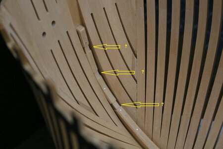
Speaking of problems...at the bow I always knew that I needed to refine the inner face of the hawse timbers to establish their proper thickness. I postponed that until seeing how they related to the stemson. Well, its worse than I could have ever imaged. Check this out:
View attachment 393438
The stemson should be proud of the hawse timbers by the thickness of the planks that will terminate into it (as you can see it is rather substantially submerged).
I need to think about how to solve this issue without damaging the stemson and still end up with a reasonably contoured (faired) inner face of the hawse timbers. I sure wish I knew what I was doing...
….and Paul makes this statement on only his 2nd ship…and a complicated POF build…I sure wish I knew what I was doing...
Paul, just thinking out loud, it appears to me sanding the haws timbers to match the stemson (as it is placed now) would throw the inner hull way out of plan shape. It looks like you have a hooked scarf right at the perfect location at the lower beginning of the haws timbers where you could map a new stemson based on the haws timber's location provided you have enough spare wood to do that.This week I turned my attention to the keelson. It is made of five segments along its length with each of the segments joined by a hooked scarf joint. At the bow of the ship the last portion of the keelson tapers from 12" wide to 9" wide and is then joined to the 9" wide stemson.
The kit design calls for a simplified keelson (and keel) that lack the notches on the facing segments commonly seen on other (more impressive) POF builds. I was happy to follow the simplified design as the notched faces are impossible to see on a completed model.
My very first hooked scarf joint in clamps:
View attachment 393430
Another one, but now sanded to the proper height of 13":
View attachment 393432
The upper edge of the keelson (and stemson) receives a bevel. I'm sure there is a way to make the bevel using a mill or a scraping tool. I just used files:
View attachment 393433
The bevels on the stemson (the notches are for breasthooks and deck hooks to be added later):
View attachment 393434
The top of the stemson must be placed precisely as it eventually establishes the vertical position of the upper deck (I used a gauge set to a measurement taken from the plans):
View attachment 393431
The keelson is bolted to the keel with 1.25" bolts (every other frame). I used copper wire and will postpone burnishing the ends until I see what happens to them naturally:
View attachment 393435
And the scarf joints also receive smaller bolts (0.75") at the ends of the joined timbers (lip bolts?):
View attachment 393436
I am more than a little annoyed that these are not round. All I can think of is that I compressed/distorted the copper wires while inserting them. I'm not sure how many more bolts will be used on this ship, but I need to solve this problem.
The overall view and a closer look of the installed keelson:
View attachment 393437
View attachment 393439
Speaking of problems...at the bow I always knew that I needed to refine the inner face of the hawse timbers to establish their proper thickness. I postponed that until seeing how they related to the stemson. Well, its worse than I could have ever imaged. Check this out:
View attachment 393438
The stemson should be proud of the hawse timbers by the thickness of the planks that will terminate into it (as you can see it is rather substantially submerged).
I need to think about how to solve this issue without damaging the stemson and still end up with a reasonably contoured (faired) inner face of the hawse timbers. I sure wish I knew what I was doing...
- Joined
- Oct 23, 2018
- Messages
- 718
- Points
- 353

Hi Paul
as far as I remember you need 6 small nails for the connection of the keelson parts. The joinery looks really good.
as far as I remember you need 6 small nails for the connection of the keelson parts. The joinery looks really good.
- Joined
- Dec 16, 2016
- Messages
- 1,096
- Points
- 493

Paul, Don’t worry, it’ll turn out right, I’ve gone through my whole life saying to myself, “ I sure wish that I knew what I was doing “ and life has still turned out pretty good. KenThis week I turned my attention to the keelson. It is made of five segments along its length with each of the segments joined by a hooked scarf joint. At the bow of the ship the last portion of the keelson tapers from 12" wide to 9" wide and is then joined to the 9" wide stemson.
The kit design calls for a simplified keelson (and keel) that lack the notches on the facing segments commonly seen on other (more impressive) POF builds. I was happy to follow the simplified design as the notched faces are impossible to see on a completed model.
My very first hooked scarf joint in clamps:
View attachment 393430
Another one, but now sanded to the proper height of 13":
View attachment 393432
The upper edge of the keelson (and stemson) receives a bevel. I'm sure there is a way to make the bevel using a mill or a scraping tool. I just used files:
View attachment 393433
The bevels on the stemson (the notches are for breasthooks and deck hooks to be added later):
View attachment 393434
The top of the stemson must be placed precisely as it eventually establishes the vertical position of the upper deck (I used a gauge set to a measurement taken from the plans):
View attachment 393431
The keelson is bolted to the keel with 1.25" bolts (every other frame). I used copper wire and will postpone burnishing the ends until I see what happens to them naturally:
View attachment 393435
And the scarf joints also receive smaller bolts (0.75") at the ends of the joined timbers (lip bolts?):
View attachment 393436
I am more than a little annoyed that these are not round. All I can think of is that I compressed/distorted the copper wires while inserting them. I'm not sure how many more bolts will be used on this ship, but I need to solve this problem.
The overall view and a closer look of the installed keelson:
View attachment 393437
View attachment 393439
Speaking of problems...at the bow I always knew that I needed to refine the inner face of the hawse timbers to establish their proper thickness. I postponed that until seeing how they related to the stemson. Well, its worse than I could have ever imaged. Check this out:
View attachment 393438
The stemson should be proud of the hawse timbers by the thickness of the planks that will terminate into it (as you can see it is rather substantially submerged).
I need to think about how to solve this issue without damaging the stemson and still end up with a reasonably contoured (faired) inner face of the hawse timbers. I sure wish I knew what I was doing...
Hi Paul,This week I turned my attention to the keelson. It is made of five segments along its length with each of the segments joined by a hooked scarf joint. At the bow of the ship the last portion of the keelson tapers from 12" wide to 9" wide and is then joined to the 9" wide stemson.
The kit design calls for a simplified keelson (and keel) that lack the notches on the facing segments commonly seen on other (more impressive) POF builds. I was happy to follow the simplified design as the notched faces are impossible to see on a completed model.
My very first hooked scarf joint in clamps:
View attachment 393430
Another one, but now sanded to the proper height of 13":
View attachment 393432
The upper edge of the keelson (and stemson) receives a bevel. I'm sure there is a way to make the bevel using a mill or a scraping tool. I just used files:
View attachment 393433
The bevels on the stemson (the notches are for breasthooks and deck hooks to be added later):
View attachment 393434
The top of the stemson must be placed precisely as it eventually establishes the vertical position of the upper deck (I used a gauge set to a measurement taken from the plans):
View attachment 393431
The keelson is bolted to the keel with 1.25" bolts (every other frame). I used copper wire and will postpone burnishing the ends until I see what happens to them naturally:
View attachment 393435
And the scarf joints also receive smaller bolts (0.75") at the ends of the joined timbers (lip bolts?):
View attachment 393436
I am more than a little annoyed that these are not round. All I can think of is that I compressed/distorted the copper wires while inserting them. I'm not sure how many more bolts will be used on this ship, but I need to solve this problem.
The overall view and a closer look of the installed keelson:
View attachment 393437
View attachment 393439
Speaking of problems...at the bow I always knew that I needed to refine the inner face of the hawse timbers to establish their proper thickness. I postponed that until seeing how they related to the stemson. Well, its worse than I could have ever imaged. Check this out:
View attachment 393438
The stemson should be proud of the hawse timbers by the thickness of the planks that will terminate into it (as you can see it is rather substantially submerged).
I need to think about how to solve this issue without damaging the stemson and still end up with a reasonably contoured (faired) inner face of the hawse timbers. I sure wish I knew what I was doing...
Next time try to roll the copper wire with a blunt knife to create the bolts. You will then create a bollow head on it which will only flatten while you tap it into the hole. If you tap a flat surface the shape of the round copper will disform.
Regarding the hawser timber sanding I see this proxxon tool on your most wanted list.
But are you sure these are properly installed. It seems odd that so much should be removed in a specific place.
- Joined
- Oct 17, 2020
- Messages
- 1,506
- Points
- 438

Hi Paul, sorry I have never seen these joints, can you give me some hints? FrankThis week I turned my attention to the keelson. It is made of five segments along its length with each of the segments joined by a hooked scarf joint. At the bow of the ship the last portion of the keelson tapers from 12" wide to 9" wide and is then joined to the 9" wide stemson.
The kit design calls for a simplified keelson (and keel) that lack the notches on the facing segments commonly seen on other (more impressive) POF builds. I was happy to follow the simplified design as the notched faces are impossible to see on a completed model.
My very first hooked scarf joint in clamps:
View attachment 393430
Another one, but now sanded to the proper height of 13":
View attachment 393432
The upper edge of the keelson (and stemson) receives a bevel. I'm sure there is a way to make the bevel using a mill or a scraping tool. I just used files:
View attachment 393433
The bevels on the stemson (the notches are for breasthooks and deck hooks to be added later):
View attachment 393434
The top of the stemson must be placed precisely as it eventually establishes the vertical position of the upper deck (I used a gauge set to a measurement taken from the plans):
View attachment 393431
The keelson is bolted to the keel with 1.25" bolts (every other frame). I used copper wire and will postpone burnishing the ends until I see what happens to them naturally:
View attachment 393435
And the scarf joints also receive smaller bolts (0.75") at the ends of the joined timbers (lip bolts?):
View attachment 393436
I am more than a little annoyed that these are not round. All I can think of is that I compressed/distorted the copper wires while inserting them. I'm not sure how many more bolts will be used on this ship, but I need to solve this problem.
The overall view and a closer look of the installed keelson:
View attachment 393437
View attachment 393439
Speaking of problems...at the bow I always knew that I needed to refine the inner face of the hawse timbers to establish their proper thickness. I postponed that until seeing how they related to the stemson. Well, its worse than I could have ever imaged. Check this out:
View attachment 393438
The stemson should be proud of the hawse timbers by the thickness of the planks that will terminate into it (as you can see it is rather substantially submerged).
I need to think about how to solve this issue without damaging the stemson and still end up with a reasonably contoured (faired) inner face of the hawse timbers. I sure wish I knew what I was doing...
Hmm. You might be right about the amount of reshaping that is necessary. I may have to do both. The thing is---I don't really know how to figure out what the 'plan shape' is in that area. I have a cross section that shows the shape at the midline of the vessel (no problems there), but I don't really know how to interpret and apply the swoopy line drawings I purchased recently from Harold Hahn's son (his dad built the Kingfisher) which probably contain the information I need. But I DO know the anatomy of the stemson (definitively) so that needs to drive the ship (as it were) with regard to figuring out the correct solution.Paul, just thinking out loud, it appears to me sanding the haws timbers to match the stemson (as it is placed now) would throw the inner hull way out of plan shape. It looks like you have a hooked scarf right at the perfect location at the lower beginning of the haws timbers where you could map a new stemson based on the haws timber's location provided you have enough spare wood to do that.
David shows 4x but I have seen far more examples of scarf joints using 6x (than 4x). In other words, I suspect you are correct!Hi Paul
as far as I remember you need 6 small nails for the connection of the keelson parts. The joinery looks really good.
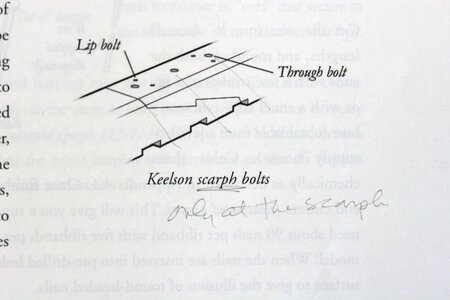
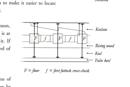
Image credits: Antscherl, TFFM, Volume 1 (revised), Page 179.
Hi Paul, sorry I have never seen these joints, can you give me some hints? Frank
View attachment 393539
Hi Frank. I am always grateful for your watchful eye! With the inclusion of these notches I am following the plans found in David Antscherl, The Fully Framed Model series of books on building swan class ship models. Here is an image from volume 1 that guided my work:
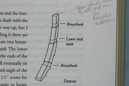
BUT! I doubt they were on the real ship. I think they are only included to assist the modeler in properly placing the breasthooks and deck hooks. Eventually these notches will be hidden and will no longer be visible on the stemson.
In other words, you are correct to wonder why they are there!
I hope this all translates well into Italian...
Thanks Maarten. I think a rounded head would have looked better than what I have done. Next time!Hi Paul,
Next time try to roll the copper wire with a blunt knife to create the bolts. You will then create a bollow head on it which will only flatten while you tap it into the hole. If you tap a flat surface the shape of the round copper will disform.
Regarding the hawser timber sanding I see this proxxon tool on your most wanted list.
But are you sure these are properly installed. It seems odd that so much should be removed in a specific place.
That tool looks fun - and I wish I had it when I was fairing the hull - but it looks way too big for this compressed space (?).
But are you sure these are properly installed. It seems odd that so much should be removed in a specific place.
Well, I'm more sure about the placement of the stemson/apron/stem than I am about the placement and shape of the hawse timbers/bollard timbers (see my comments above to Daniel). I did very little shaping of the inner surface of the hawse timbers and left them oversized - I just didn't think they were THAT oversized - and so ODDLY oversized in one area only. In other words, I share your concerns...
I always admire your tenacity in these situations. Barring any relevant research in this area, as a last resort you can always assume the hawse hull shape as correct as this design allows for and build the stemson out accordingly. I know this is no real help and I'm not really saying anything you don't already know. Again, just thinking out loud.I don't really know how to figure out what the 'plan shape' is in that area.
True story, as Grant would say. Despite the issues to be resolved, your work is incredibly precise Paul, and a pleasure to observe.You’ll figure it out, Paul. You always do.
Extremely clean work Paul.
If it were me, I would slice through the Stemson at the base of the Lower breasthook notch and fashion a replacement section. Cut the section over size and place scrap planking up against the new piece to determine where the inside face of the planking lines through with the shape. You can then add additional material to this line before cutting if you want the Stemson to be proud of the planking
Hope this makes sense
My thanks to everyone who offered encouraging words and suggestions for how I should address this little problem. I wish I could tell you that I allowed some time away from the model for careful formulation of a restorative plan. But it turns out I lack that level of personal maturity. For the record, this unwillingness (inability?) to allow problems the necessary resolution time got my keester in a ringer working on the hull of my Vasa so it would seem that I am untrainable in this regard.
I tried to locate line drawings that would provide some insight but all I could find was guidance regarding the outside of the hull. I then used some long-armed calipers to measure the thickness of the bollard and hawse timbers and realized just how thick I had left these in the lower half of the hull. I then pulled up my collection of Kingfisher build logs and became further convinced that the issue resided in the thickness (not the position) of the bollard and hawse timbers.
Some careful work with woodworking chisels and then a variety of sanding tools consumed the next two work sessions.
As a reminder, here is where I was on Friday:
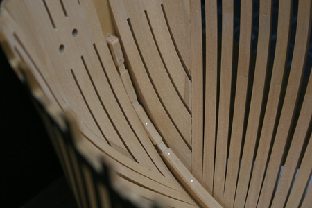
After now just a few minutes ago:
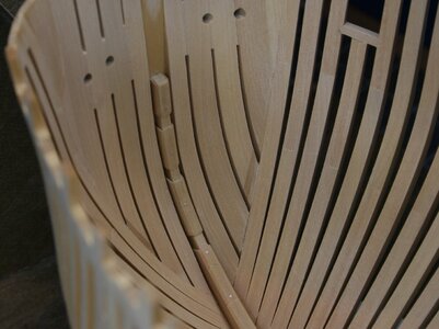
Not perfect, but I think I'm back in the game... Sadly, I cannot be fully confident that my solution was the proper one. If it's not...well, let's hope I don't need to go there...
Thank you for your ongoing interest and involvement with this build report!
I tried to locate line drawings that would provide some insight but all I could find was guidance regarding the outside of the hull. I then used some long-armed calipers to measure the thickness of the bollard and hawse timbers and realized just how thick I had left these in the lower half of the hull. I then pulled up my collection of Kingfisher build logs and became further convinced that the issue resided in the thickness (not the position) of the bollard and hawse timbers.
Some careful work with woodworking chisels and then a variety of sanding tools consumed the next two work sessions.
As a reminder, here is where I was on Friday:

After now just a few minutes ago:

Not perfect, but I think I'm back in the game... Sadly, I cannot be fully confident that my solution was the proper one. If it's not...well, let's hope I don't need to go there...
Thank you for your ongoing interest and involvement with this build report!
I like the makeover...what ever you did...
At first my thought was: What a brave man. But no, you do was you have to do after considering your options. This seems to be the right way: little by little sanding and the Stemson will come in line.My thanks to everyone who offered encouraging words and suggestions for how I should address this little problem. I wish I could tell you that I allowed some time away from the model for careful formulation of a restorative plan. But it turns out I lack that level of personal maturity. For the record, this unwillingness (inability?) to allow problems the necessary resolution time got my keester in a ringer working on the hull of my Vasa so it would seem that I am untrainable in this regard.
I tried to locate line drawings that would provide some insight but all I could find was guidance regarding the outside of the hull. I then used some long-armed calipers to measure the thickness of the bollard and hawse timbers and realized just how thick I had left these in the lower half of the hull. I then pulled up my collection of Kingfisher build logs and became further convinced that the issue resided in the thickness (not the position) of the bollard and hawse timbers.
Some careful work with woodworking chisels and then a variety of sanding tools consumed the next two work sessions.
As a reminder, here is where I was on Friday:
View attachment 393747
After now just a few minutes ago:
View attachment 393749
Not perfect, but I think I'm back in the game... Sadly, I cannot be fully confident that my solution was the proper one. If it's not...well, let's hope I don't need to go there...
Thank you for your ongoing interest and involvement with this build report!
And the proof again:
In Dutch we say: “Meter = weten!” / To measure is to know.I then used some long-armed calipers to measure the thickness of the bollard and hawse timbers and realized just how thick I had left these in the lower half of the hull.
Regards, Peter
- Joined
- Jan 9, 2020
- Messages
- 10,521
- Points
- 938

Dear Paul. At first, when reading about your issue, I was going to suggest going Dutch - no, not the3 restaurant kind, but the shipwright one. If the hawse timbers and keelson are not in the correct proportion to each other, change the keelson. I should have known better than to think that you will ever choose the easy way! I can well imagine that the reshaping must have taken two sessions (boxwood and all), but oh boy, was it worth it! Once again you have come up trumps and are certainly back in the game.
Problem solved, well done Paul.
Hi Paul,
It is a proxxon tool which means small in size. I have one myself for faring the inside of a hull.
Disc size is 50 mm. Ofcourse don't know the available space in your model.
Do know you like a good workout and don't fear some elbow grease as you have shown already above. A very good fix indeed
It is a proxxon tool which means small in size. I have one myself for faring the inside of a hull.
Disc size is 50 mm. Ofcourse don't know the available space in your model.
Do know you like a good workout and don't fear some elbow grease as you have shown already above. A very good fix indeed
My my, your experience of working inside anatomical cavities has certainly paid dividends
Well done.
Well done.
Thanks guys! There are some growing deficiencies in my model that make the perfectionist in me embrace the realities of what I KNOW, and what I am capable of DOING. All that to say: it may not be quite right, but it's right enough for today.
I have a couple of favorite reference build reports and my progress to date puts me on page 2, 3, or 4 of what are 50-60 page reports. In other words - there are lots of battles to be fought before the war is done. This was an unexpected skirmish of which there will certainly be more.
The learning curve is so steep! I have once again (reference: Vasa) foolishly selected to try to build something I have no business attempting. A wise man would respect the process of learning a craft but I'm too old and too fond of overreaching to 'waste time' learning how to do something the proper way (i.e. start small and simple and add knowledge and skills in a natural way).
ACKNOWLEDGEMENT: I did not take some sound advice offered here. I want you to know that I was not, nor will I be in the future, dismissive or unappreciative of the fact that you took the time to post your thoughts and suggestions. I am fully capable of receiving advice well and will certainly do so in the future. In this case, I have always felt uneasy about the hawse timbers so I simply assumed that they were the source of the problem over-against the stemson which I could fabricate from a pattern...
OK, that's enough prose. Now I have to figure out something called 'limber strakes'...
Kurt Konrath
Kurt Konrath
Think of how a dentist would smooth fillings next to a new crown, and the method will come to you.


