Gute, saubere und genaue Arbeit 
-

Win a Free Custom Engraved Brass Coin!!!
As a way to introduce our brass coins to the community, we will raffle off a free coin during the month of August. Follow link ABOVE for instructions for entering.
-

PRE-ORDER SHIPS IN SCALE TODAY!
The beloved Ships in Scale Magazine is back and charting a new course for 2026!
Discover new skills, new techniques, and new inspirations in every issue.
NOTE THAT OUR FIRST ISSUE WILL BE JAN/FEB 2026
You are using an out of date browser. It may not display this or other websites correctly.
You should upgrade or use an alternative browser.
You should upgrade or use an alternative browser.
La Belle Poule 1780 by Thomas
- Thread starter Thomas Marocke
- Start date
- Watchers 38
I have started the 2nd stage of construction, the construction of the underwater ship. For this purpose, an assembly facility is provided.
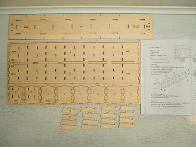
The individual parts.
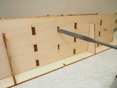
In order to assemble the individual parts without jamming, the recesses must be filed a little.
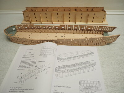
The assembly device put together without glue, ready to receive the upper ship.
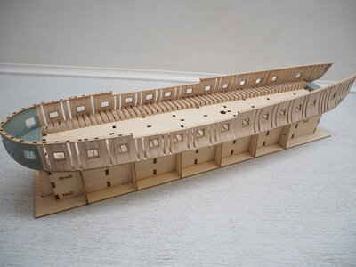
Test with the upper hull in place.
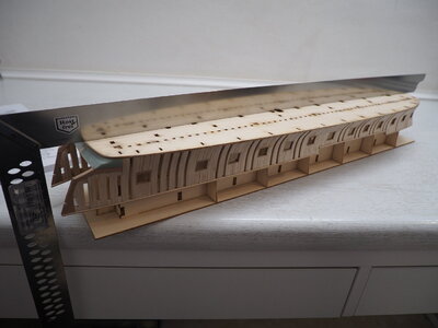
And so the construction can continue. One last test with a steel ruler to make sure everything is straight, and I can continue building.
Best regards
Thomas

The individual parts.

In order to assemble the individual parts without jamming, the recesses must be filed a little.

The assembly device put together without glue, ready to receive the upper ship.

Test with the upper hull in place.

And so the construction can continue. One last test with a steel ruler to make sure everything is straight, and I can continue building.
Best regards
Thomas
It remains a beautiful sight, such a special construction method with partial jigs. Nice and accurate work, Thomas.I have started the 2nd stage of construction, the construction of the underwater ship. For this purpose, an assembly facility is provided.
View attachment 344218
The individual parts.
View attachment 344222
In order to assemble the individual parts without jamming, the recesses must be filed a little.
View attachment 344219
The assembly device put together without glue, ready to receive the upper ship.
View attachment 344220
Test with the upper hull in place.
View attachment 344221
And so the construction can continue. One last test with a steel ruler to make sure everything is straight, and I can continue building.
Best regards
Thomas
Regards, Peter
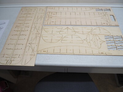
The components for the underwater ship.
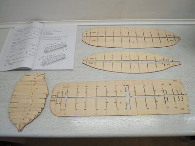
The components removed from the plates.
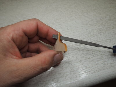
So that all parts fit into each other without jamming, all slots were filed open a little. Here the disadvantage of the thin 2 mm plywood plates showed up. Especially at the fine tips the wood tends to split. Only with very careful processing it went out without damage.
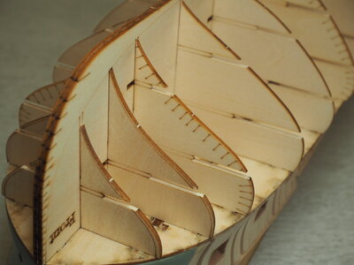
Dry mounting on the bow.
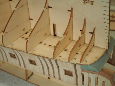
And on the stern.
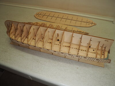
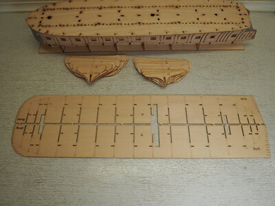
To glue the two-piece "spine" (keel) together and to work on it, everything had to be disassembled again. Because all the slots were already widened a bit, it was no problem.
I wish all a nice weekend
Thomas
How to glue a two-peace keel plate together without distortion! I was faced with this problem today.
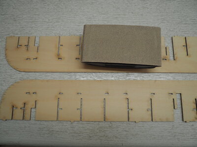
First each plate was sanded with 150 grit sandpaper to slightly roughen the surfaces a bit.
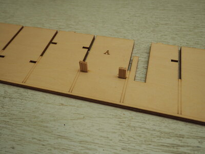
Now the glue was applied to one plate and both plates were pressed against each other with the hands and the glue was rubbed in by circular movements of the plates. Then, in several places passport woods were used to avoid slipping of the plates during the open time of the glue.
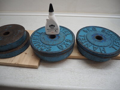
What the weight plates are not all good for. Now everything is allowed to dry out for 24 hours. Now I also know that my countertop is stable.
Best regards
Thomas

First each plate was sanded with 150 grit sandpaper to slightly roughen the surfaces a bit.

Now the glue was applied to one plate and both plates were pressed against each other with the hands and the glue was rubbed in by circular movements of the plates. Then, in several places passport woods were used to avoid slipping of the plates during the open time of the glue.

What the weight plates are not all good for. Now everything is allowed to dry out for 24 hours. Now I also know that my countertop is stable.
Best regards
Thomas
Looking very good -
I have one question, because I am a little bit confused
Are there two different jigs?
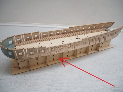
this one is under the waterline
and
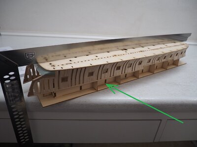
this one insatlled at the deck, so you can have a stabile base and can make the ships hull bulkheads and planking etc.
But for which works is the first one (marked with red arrow)?
I have one question, because I am a little bit confused
Are there two different jigs?

this one is under the waterline
and

this one insatlled at the deck, so you can have a stabile base and can make the ships hull bulkheads and planking etc.
But for which works is the first one (marked with red arrow)?
Hi Uwe!
The mounting platform is the same in both photos. First, the upper part of the ship (red arrow) is placed on the mounting platform for a test run. When it fits exactly into the slots provided, it can be turned over for further assembly (green arrow). If the assembly of the upper part has been carried out exactly, this will now also work.
The upper part of the ship fits very tightly onto the platform. If it does not fit, the fault must be found. This may be a frame that is a few tenths of a millimeter too far inward or adhesive residues that must be removed.
Best regards
Thomas
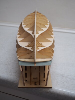
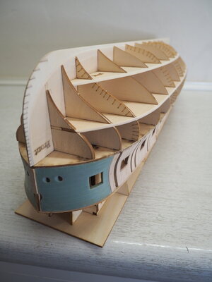
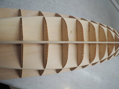
The false keel was narrowed from 4,1 mm to 2,1 mm according to the instructions. The false keel together with the planks then gives the correct width of the real keel. (If all goes well).

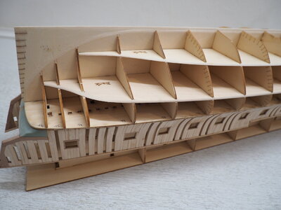
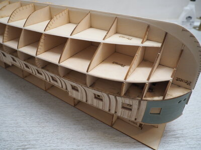
The horizontal plates for stabilizing the frames had to be ground to match the shape of the hull. So far, everything is loosely plugged together. When everything is glued together the three front and rear frames will be adjusted to the shape of the hull. At the moment they are too fragile to work on.
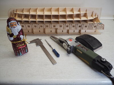
The tools for the sanding work. Except for the electric belt sander, everything was done by hand.
I wish you all a wonderful Christmas season!
Best regards
Thomas
Last edited:
Thomas, happy and reflective holidays to you too.
I appreciate your careful and thoughtful approach here Thomas. A good example to follow. Merry Christmas to you as well. May you experience the full blessings of the season.View attachment 346641
View attachment 346643
View attachment 346649
The false keel was narrowed from 4,1 mm to 2,1 mm according to the instructions. The false keel together with the planks then gives the correct width of the real keel. (If all goes well).
View attachment 346642
View attachment 346645
The horizontal plates for stabilizing the frames had to be ground to match the shape of the hull. So far, everything is loosely plugged together. When everything is glued together the three front and rear frames will be adjusted to the shape of the hull. At the moment they are too fragile to work on.
View attachment 346647
The tools for the sanding work. Except for the electric belt sander, everything was done by hand.
I wish you all a wonderful Christmas season!
Best regards
Thomas
View attachment 346644
Your belt sander looks gigantic next to La Belle Poule. Very accurate work, and certainly on this scale.
Merry Christmas Thomas
Merry Christmas Thomas
Merry Christmas and Happy Holidays Season, Tomas! keep up the great modeling !
A very Merry Christmas to you and your family Thomas.
Even in these special times, you can still find one hour or two for shipbuilding.
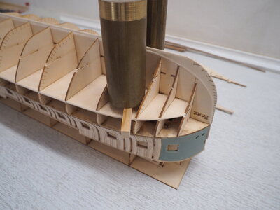
The challenge now was in what order to assemble the underwater hull. I decided to loosely attach the frames to the "false keel" and then glue only the "false keel" with wood glue. I quickly inserted two horizontal stabilizing boards and let the keel dry.
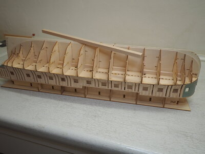
After the glue had dried, additional holding blocks were glued in place, as done in furniture construction for cabinet floors.
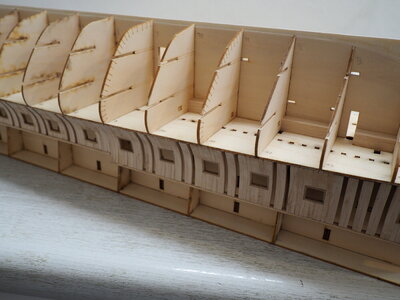
The keel and the frames are now mounted at right angle. The frames will be glued later.
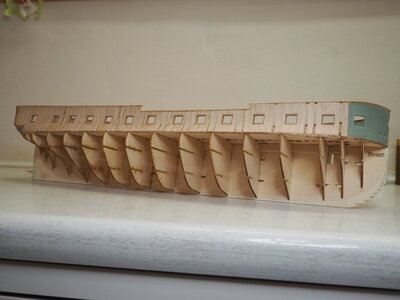
The hull removed from the assembly platform on a trial basis. It could be carefully detached from the mold and was not accidentally glued to it. Now you can clearly see that a ship is being built.
Best regards
Thomas

The challenge now was in what order to assemble the underwater hull. I decided to loosely attach the frames to the "false keel" and then glue only the "false keel" with wood glue. I quickly inserted two horizontal stabilizing boards and let the keel dry.

After the glue had dried, additional holding blocks were glued in place, as done in furniture construction for cabinet floors.

The keel and the frames are now mounted at right angle. The frames will be glued later.

The hull removed from the assembly platform on a trial basis. It could be carefully detached from the mold and was not accidentally glued to it. Now you can clearly see that a ship is being built.
Best regards
Thomas
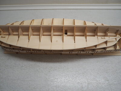
The further assembly with stabilizing blocks.
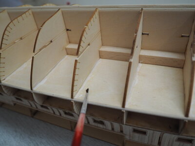
The bulkheads were finally glued.
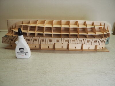
All necessary components are firmly glued. After the attachment of the keel, the hull would be ready for planking.
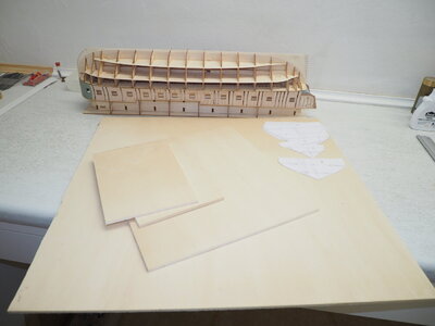
I am bothered by the distance of four centimetres between the bulkheads. I want a firmer and pressure-resistant contact surface for the planking and therefore I got myself an additional six millimeters of plywood.
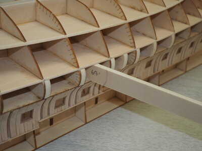
The dimensions can be drawn on the existing widest neighbouring bulkhead and then the wood can be sawn out and inserted. This results in very little grinding work later on.
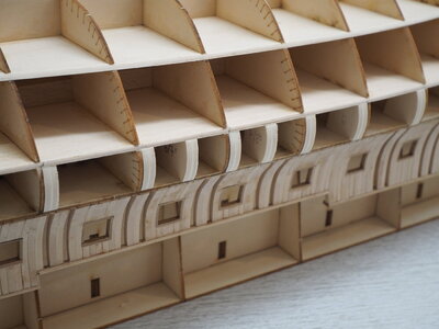
Now there is only a blank space of 14 millimeters between the frames.
Best regards
Thomas


