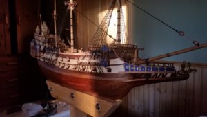
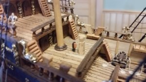
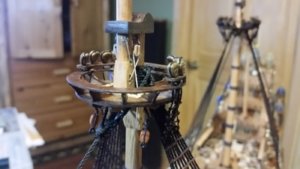
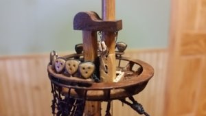
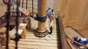
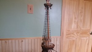
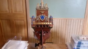
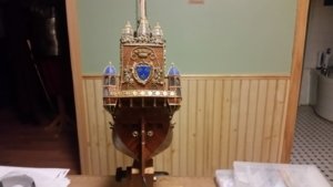
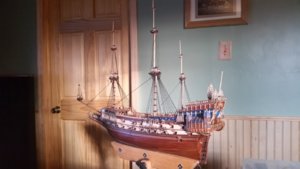
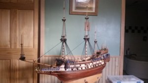
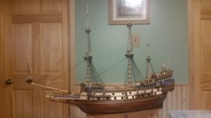
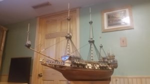
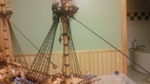
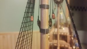
La Couronne Corel/scratch 1:100 First build [COMPLETED BUILD]

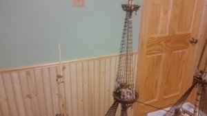
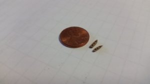
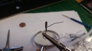
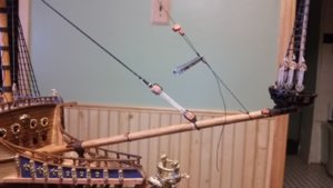
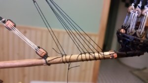
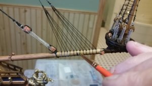
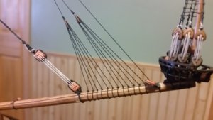
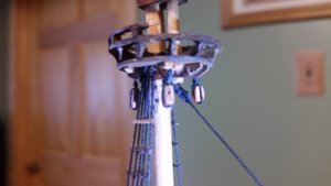
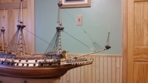
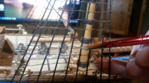
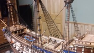
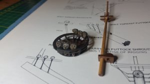
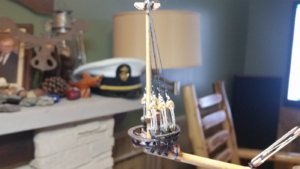
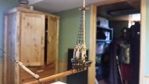
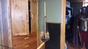
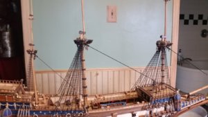
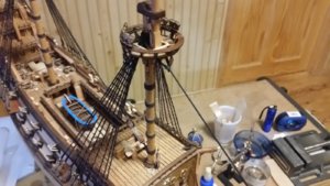
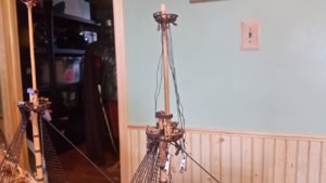
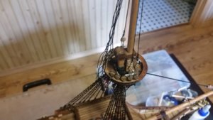
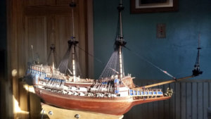
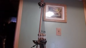
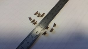
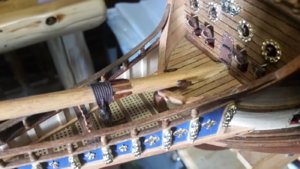
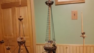
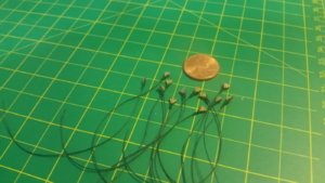
Ratlines for the lower masts are finished. A mixture of PVA and water was applied to the knots to help hold them in place. CA glue was applied to the first and last knot on each ratline. Some brass 0.062mm diameter pins were purchased and are starting to be formed around the 5mm lower deadeyes for the spritsail topmast. The brass will be blackened. At the bottom of the deadeyes will be hooks. Futtocks will be hooked to the bottom of the deadeye assemblies and the lower ends bolted to the sides of the bowsprit. Brass to simulate these will be formed form wire and blackened to appear as iron. There are plenty of directions to go in building the model from here. The upper stays and shrouds for the topmasts and topgallants are probably next after the shrouds on the spritsail topmast are done. The upper masts and spritsail topmast are still not yer glued together, and that will be done before more shrouds and stays are rigged.

764 Apply PVA Glue to Knots.jpg

765 Lower Ratlines Done.jpg

766 Brass Wire Around Spritsail Topmast Deadeyes.jpg

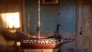
767 Progress So Far.jpg
 
6 hours ago, EJ_L said:
Those ratlines look great! That jig is indeed a great tool for helping keep the shrouds aligned and spacing even. I saw it years ago on other builds and implemented it myself on the past two. Will never go back to trying to eyeball them again. You are making excellent progress through the standing rigging and it only gets easier as you go up, less of it. Beautiful work as always!
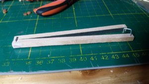
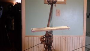
I had to eyeball only the few rows near the top and at the bottom where the spacing tool interfered with the hull or a top. I found that when tightening each clove hitch, you pull the thread away from the shroud straight toward you with a light tug while holding the shroud with needle pliers just above the knot, with the spacing tool just below the knot, then tug the line in a direction parallel with the ratline, in the direction you are working. The knot is small and tight. I tighten each knot as I go, and then slide them up or down on the shroud if they need straightening. The spacing tool makes sure that the row is mostly in the correct angle, but properly spaced between rows, so few adjustments are necessary. Every three rows, I check the height and location of the ratline to the channel, and compare that measurement to the ratline on the opposite side of the ship, so they line up. Use of the spacing tool made these measurements usually come within 1mm from port to starboard, so adjustments are quite small to match the ratlines. It's good to apply the thinned PVA glue to each row before making the next one, so none of your finished knots get loose. It took me about 200 knots to get a system down. The last rows of ratlines I did look a lot better than the first ones. Here is the improved ratline spacing tool, with metal clips made from a large paperclip. Make the thickness of the tool the distance you want between the ratlines. There are strips of 300 grit sandpaper glued to the inside surfaces of the wood to grip the shrouds.

768 Improved Ratline Spacing Tool.jpg
 
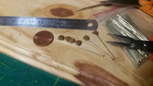
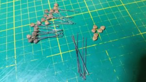
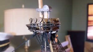
The lower deadeyes for the spritsail topmast and the topmasts for fore, main and mizzen were prepared with blackened brass pins. Loops will be formed at the bottom of these deadeyes to accept hooks of the futtock shrouds. The round deadeyes were replaced with triangular ones, which fit the age of the ship better. The lower deadeyes were completed for the spritsail topmast and installed in the rail of the top.

769 Fashion Lower Deadeyes for Topmast Tops.jpg770 Installed Lower Deadeyes in Spritsail Topmast Top.jpg
 
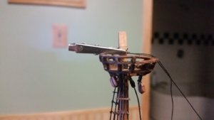
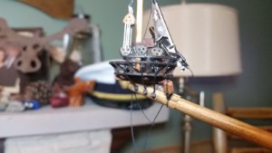
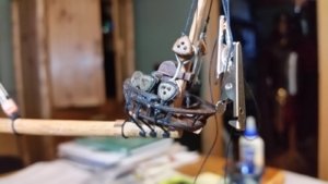
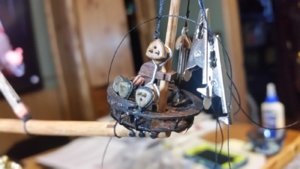
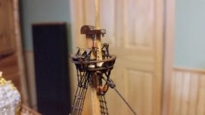
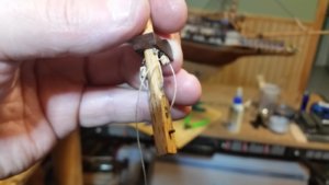
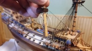
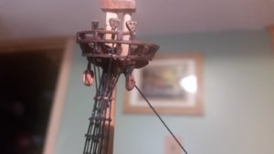
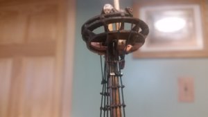
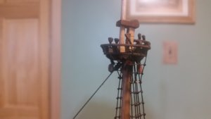
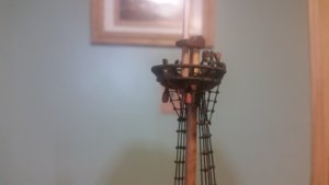
Work on the spritsail topmast continues. Metal futtock shrouds irons were fashioned from brass, blackened, then painted (my blackening keeps flaking off when the metal is shaped). The upper ends are hooked into the deadeye strops. The lower ends were fastened to the bowsprit by brass pins glued into holes made with a Dremel. Now that the lower deadeyes had support, shroud pairs were made and seized at the top with thin thread just like on the masts. Another deadeye spacing tool was made using two deadeyes, a paperclip, and some brass pins. The upper deadeyes were lashed with lanyards in the same manner as the other masts. Overhand knots with thin black thread were used to make seizes in three places for each shroud. One lashes the shroud end to its standing part at the top of the deadeye. The other two secure the end of the shroud to the standing part above the deadeye. The bitter end of the deadeye lanyard is wrapped twice around the shroud, then half-hitched, and the remainder was simply glued to the backside of the shroud, since the seizes for it would be 100 times larger than scale for this model. One can only go so small.

771 Futtock Shroud Irons.jpg

772 Lashing Deadeyes With Spacing Tool.jpg

773 Seizing Shroud Using Glued Overhand Knots.jpg

774 Completed Spritsail Topmast Shrouds.jpg
 
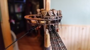
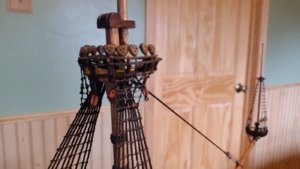
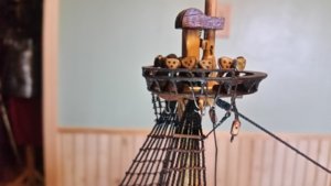
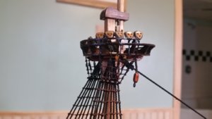
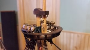
Holes were drilled in the upper rail of the foremast top for the deadeyes and futtuck shroud irons (puttocks). After inserting the brass wire which served as the deadeye puttock plates, similar to the chain plates for the lower masts. I began to shape the wire to the profile of the top and angle them toward the lower shrouds. While forming the fourth puttock plate with pliers and fingers, I heard that sickening crunch that all ship modelers fear, the sound of breaking wood. The upper rail, weakened by the holes and under strain from forming the wire shattered. After saying several loud single syllable words that were appropriate to the situation, the remains of the upper rail were removed with a razor knife, and a new rail constructed from scratch. Small pieces of wood were used to restore the height of three damaged rail supports. The stress was caused by forcing the wire to travel through the upper rail and outboard of the inner rail. Bending the wire toward the shrouds pried the upper rail into pieces. The new rail was installed after drilling holes through it and the lower rail. The futtock irons were changed to pass through the upper and lower rails, to avoid breaking the thin wooden parts again. The new rail looks better, and I am considering replacing the upper rails on the main and mizzen masts as well.

The ends of the puttock plates were cut to length, and needle nose and round nose pliers were used to form hooks at the bottom ends of the irons. Futtock shrouds were made with siezed loops at the top which were laid onto the puttock plate hooks. The hooks were then carefully closed with pliers to form eyes. Now to attach the futtock shrouds to the lower shrouds.

I decided that just tying them to the lower shrouds wasn't good enough. The ratline at the location where the futtock shrouds connect was nothing more than a close pile of knots, and it didn't look good. So, I cut the topmost ratline off, and replaced it with a 0.5mm x 0.5mm strip of walnut and glued it directly to the shrouds to serve as the futtock staff. The futtock shrouds were secured by making a single wrap around the futtock staff and simultaneously around one of the lower shrouds, and glued in place. The extra length was trimmed off inboard of the shrouds. The port side futtock shrouds for the foremast are now down, and the starboard side is next. After that, ratlines will be added to the futtock shrouds.

777 Progress So Far.jpg

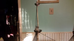
778 Progress So Far.jpg

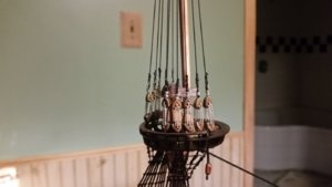
779 Foremast Top Deadeyes.jpg

780 Foremaps Top Futtock Scrouds.jpg
 
751 Mizzenmast Stay Installed.jpg
Those kevels look great. I'm curious, are they something that was included in the Corel kit, or were those a scratch edition? Enjoying watching this build, and hoping to tackle a Couronne some day.
 
Those kevels look great. I'm curious, are they something that was included in the Corel kit, or were those a scratch edition? Enjoying watching this build, and hoping to tackle a Couronne some day.
Hello Brewbrarian,

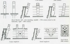
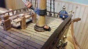
The kevels are part of the Corel kit, however the horizontal part of the kevel was scratch built. The kevels are overly large for this model, and I really should have made staghorn kevels from scratch. The horns of the kevel should stand away from the bulwark and not project above it unless they are large. Below are some examples from Wolfram zu Mondfeld's Historic Ship Models.

Capture.JPG
 
Last edited:
Today the mizzenmast futtock shrouds were rigged along with their ratlines. The deadeyes are 3mm deadeyes from Model-Shipyard.com and are actually made from three layers of laser cut cardboard glued together. I hope they are as strong as wood deadeyes. Now it's time to rig the top-ropes, which hoist the topmasts up into position. These ropes are usually rigged temporarily and their blocks and lines are removed once the topmasts are secured in positions aloft. Since EJ put them on his model, I did to. I can leave off the top-ropes for hoisting the topgallants masts and keep things simple. One problem I noticed was that the blocks which are on the deck for each of the top-rope tackles were single blocks. So, I removed them and replaced all three with double blocks. It was tight in there, but they were replaced without any accidents.

The topmasts and caps were glued down into their final positions, and the top-ropes were rigged, starting with tying the line to an eyelet under each cap, running the line through two sheaves in each mast and two blocks hung by hooks on the caps, then running the line down through the top on the port side toward the deck, ending in a single block. A lanyard lashed that block to the double block secured to the deck. After hitching the bitter end of the line above the tackles, the excess line was coiled up on the deck. The pictures below show the work on each top-rope for the foremast, mainmast and then mizzen mast. It's nice to run the very first line of the running rigging, even though the standing rigging is still incomplete higher up.

786 Mizzen Futtock Shrouds.jpg

787 Replace Deck Single Block with Double Block.jpg

788 Replace Deck Single Block with Double Block.jpg

789 Replace Deck Single Block with Double Block.jpg

790 Fore Top-Rope.jpg

791 Fore Top-Rope.jpg

792 Fore Top-Rope.jpg

793 Fore Top-Rope.jpg

794 Rig Main Top-Rope.jpg

795 Rig Main Top-Rope.jpg

796 Main Top-Rope.jpg

797 Main Top-Rope.jpg798 Mizzen Top-Rope.jpg

799 Mizzen Top-Rope.jpg
 
Today the holes in the fore topmast top were drilled to accept the topgallant futtock shrouds, and the top was glued into position. The shrouds, made of 0.5mm line from Domonoff's Workshop, were made in pairs and seized like before, with the last single set made by tying two lines together in two locations, forming a loop at the center. The knots slip to tighten the loop around the mast. I didn't try splicing the lines like the lower shrouds because they are too small. The first two sets of deadeyes have been lashed.

800 Drill Futtock Shroud Holes in Fore Topmast Top.jpg

801 Rig Fore Topmast Shrouds.jpg

802 Lash Fore Topmast Shroud Deadeyes.jpg

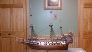
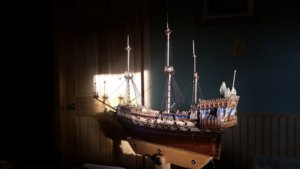
803 Ship in Sunlight.jpg
 
Last edited:
The ratlines for the fore topmast were completed. One side was done first, and the other side was periodically checked using a ruler to make sure the heights of the ratlines match port to starboard. CA glue was used on the end knots for each ratline, and watered down PVA glue was applied to the other knots.

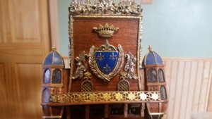
A metal cast decoration, which was originally purchased for the stern decoration but was never used, found some use at last. The angels on each side of a crest were cut apart using a hacksaw, then filed with needle files to final shape. The exposed white metal was painted over with gold metal flake paint, and the angels were added to the stern decoration on each side of the French coat of arms. Twisted brass wire was also glued on as decoration inspired by an interpretation of La Couronne at the Paris Museum of Marine Conservation. It looks better now.

The shrouds for the main topmast were cut, seized in pairs, and placed on the topmast. Then, the topmast top was glued in position on the crosstree. That's all I got done today, and it took about 8 hours.

804 Fore Topmast Shrouds Complete.jpg

805 Rig Ratlines on Fore Topmast.jpg

806 PVA Glue on Knots.jpg

807 Match Ratline Heights Port and Stbd.jpg

808 Fore Topmast Ratlines Complete.jpg

809 Added Angels to Stern Decoration.jpg

810 Stern Decoration.jpg

814 Added Wire Stern Decoration.jpg

811 Drill Futtock Shroud Holes in Main Topmast Top.jpg

812 Rig Main Topmast Shrouds.jpg

813 Glue Main Topmast Top to Crosstree.jpg
 
Last edited:
The main topmast shrouds are complete. Ratlines are next. You may have noticed that the direction the shroud is wrapped around the deadeye and the lashing lanyard pattern is a mirror opposite for the topmast shrouds when compared to the lower mast shrouds. That is because the shroud lines on the lower masts are right laid, and the topmast shrouds are left laid.

815 Main Topmast Shrouds Complete.jpg

816 Main Topmast Shrouds.jpg
 
Last edited:
Since the time for rigging the foremast stays is coming up, I needed to make some cleats and attach them to the bowsprit where they will be tied off. I used a band saw to make a column of walnut wood in the shape of a deck cleat and cut sections off that to make 7mm wide cleats. Most of the cleats were finished using a needle file and sandpaper, but some of the cleats at the top of the picture below are rough off the saw. Two cleats were attached to the bowsprit and the rest were saved for later work. Them I went back to ratline rigging, but only got the port main topmast ratlines done.


817 Fabricate Walnut Cleats.jpg

818 Glue Cleats to Bowsprit for Fore Staylines.jpg

819 Complete Stbd Main Topmast Ratlines.jpg
 
Last edited:
Today the ratlines were completed on the starboard side for the main topmast.

Then, preparations for the fore topmast stay rigging were started by making two euphroes used in the crow's feet for that stay line. A Dremel tool was used to drill a series of holes in a stick of walnut wood, then the outer profile of each euphroe was cut and shaped. To make the line bend properly as if it were bent about a sheave, the edges of the each hole were carved out using the tiny drill bit at a sharply acute angle to the hole. The blocks had their sheave holes properly shaped similarly to the line arcs more sharply in each block.

A 0.5mm stay line was prepared. A loop was and a mouse were fashioned, but the 7mm block that goes on the opposite was not attached. That comes later.

The crow's foot was rigged as follows. The euphroes were lashed to each end of a segment of line, which also passed through a 5mm block. A long length of 0.30mm line was attached to the block, and the other end of it was clamped temporarily to the top of the fore topmast. The length of this line was adjust to place the block and two euphroes at the proper distance from the bowsprit. To make sure that the lines are all equally taut in a Dutch style crow's foot stay, you start work at the bowsprit and work toward the large 7mm block at the end of the stay line. Several short segments of 0.30mm black line were cut for the lines that pass through the euphroes. You start with the line centermost relative to each euphroe, which is the line that passes through the last hole in the euphroe at its bottom end. For each line, you tie the forward end to the bowsprit with a slip knot so it stays tight on the bowsprit. Add a tad of glue to this knot. Then you pass it through the euphroe rearward and secure it to the bowsprit with an overhand bend followed by a half hitch. When the forward most euphroe line is secure by one line, run a similar line through the end of the second euphroe at the rear. Adjust the length of this line so that both euphroes are equidistant from the 5mm block above. The lanyard off the 5mm block must have enough tension to allow you to see the angles of the lines and the placement of the euphroes.

Now rig the lines for through the next hole up in each euphroe. Take care to tension each euphroe line so that the previous line does not go slack from over-tightening the next line. all three lines in each euphroe must have equal tension. This is critical if the end result is to look good. It takes several tiny adjustments making the second knot in each euphroe line and the position of the loops around the bowsprit to get everything even, so don't cinch the knots tight or apply glue until you are sure the tension is right.

When the euphroe lines are done, unclamp the 0.3mm line from the mast, and pass it through the center of a 7mm single block. You can now choose the position of the 7mm block, and lash the end of the 0.5mm stay line to the block. The take the end of the 0.30mm line and pass it through the 5mm block that was lashed to the bowsprit just behind the spritsail topmast top. run the line rearward along the bowsprit and tie it to the cleat on the side of the bowsprit over the bow deck.

So far, this line was the most fun to rig, and it looks great. I was really getting tired of ratlines! :D

820 Main Topmast Ratlines Complete.jpg

821 Fabricate Two Walnut Euphroes.jpg

821 Lashing a Euphroe.jpg

822 Begin Rigging Fore Topmast Stay.jpg

823 Line Held Temporarily With Clip on Fore Topmast.jpg

824 Begin Rigging Fore Topmast Stay Crowsfeet.jpg

825 Apply Diluted PVA Glue.jpg

826 Stay Complete.jpg

827 Fore Topmast Stay Mouse.jpg

828 Fore Topmast Stay Complete.jpg
 
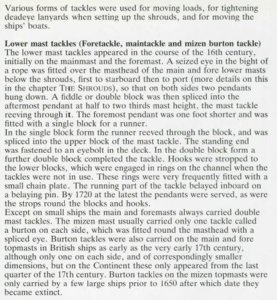
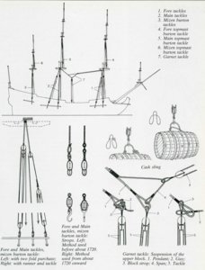
Corel shows an attachment of a single block at the center of the channels for the foremast and mainmast, to be used with running tackles that appear to be suspended from pendants attached to the masts, according to the instructions. The point where the pendants attached to the mast is not shown. After consulting Historic Ship Models by Wolfram zu Mondfeld, it seems that Corel intended to rig loading tackles for utility lifting purposes, one on each side of the masts. Usually these are rigged in sets of two on each side of a mast, one forward of the other, with both tackles hooked to an eye on the channel. See the excerpt from Historic Ship Models below for a complete description. The spliced eyes at the top of the pendants are supposed to be below the shrouds, which I have ready rigged, so this posed a problem. I took a needle and passed a double line up along the aftermost shroud, over the trestles, and down the other side to make pendants. At the end of each of these line segments, a block was rigged in accordance with zu Mondfeld's description. A single block for the forward pendants, and fiddle blocks for the aft pendants for each mast.

To complete the loading tackles, blocks will need to be attached with hooks to the eyebolts on the channels. I'm not sure yet whether or not I can squeeze short chainplates under the channels. Sometimes they were left off. I make be able to simulate with wire, similar to the chainplates for the mizzenmast. Adding these loading tackles adds more detail to the model which was only partially present in the incomplete Corel instructions.

836 Loading Tackles Explaination.JPG837 Loading Tackles Diagram.JPG

838 Begin Rigging Foremast Loading Tackles.jpg

I made the mistake of rigging the violin blocks on the tackles upside down. Oops.
839 Begin Rigging Mainmast Loading Tackles.jpg
 
Last edited:
Back
Top