-

Win a Free Custom Engraved Brass Coin!!!
As a way to introduce our brass coins to the community, we will raffle off a free coin during the month of August. Follow link ABOVE for instructions for entering.
-

PRE-ORDER SHIPS IN SCALE TODAY!
The beloved Ships in Scale Magazine is back and charting a new course for 2026!
Discover new skills, new techniques, and new inspirations in every issue.
NOTE THAT OUR FIRST ISSUE WILL BE JAN/FEB 2026
You are using an out of date browser. It may not display this or other websites correctly.
You should upgrade or use an alternative browser.
You should upgrade or use an alternative browser.
La Créole 1827 by archjofo - Scale 1/48 - French corvette
- Joined
- Oct 15, 2017
- Messages
- 1,191
- Points
- 443

Johann, Your work is, quite frankly, beyond my comprehension. I truly imagine is has a cleaner finish than on the real scale of the real ship. When I look at your hinges and other metal work I just shake my head. I would be pleased to achieve 1/2 the quality of finish work you have... KUDO my friend.
If I could say it in one sentence, "I would love to be your student.".
Thank you for sharing your work.
If I could say it in one sentence, "I would love to be your student.".
Thank you for sharing your work.
- Joined
- Nov 10, 2019
- Messages
- 479
- Points
- 373

@Tobias
@dockattner
@RDN1954
@Jimsky
@shota70
@Peter Voogt
@Uwek
@Algol1957
@Hoss6262
@mtbediz1
Thank you very much.
I would also like to thank you for the many LIKES.
That makes me happy and raises the motivation.
Making the yards - Main yard - Grande vergue
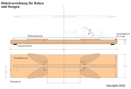
Before starting to make the yards, I made myself a planing jig in advance, inspired by Ed Tosti's build report for the clipper "Young America" in the MSW, as shown in the drawing below. Rotating and locking clamps allow lumber of various widths and lengths to be fixed in place for machining, especially with a wood planer.
To make the main yard, I prepared a drawing with dimensions based on the plan by J. Boudriot.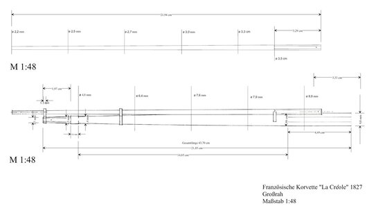
The next two pictures show how the holding device mentioned at the beginning of the report can be used in practice.
It performs valuable services in the manufacture of yards. For example, a wooden strip with a V-shaped groove was clamped in place. A square timber inserted in this way can easily be planed into an octagonal timber. In this case for the main yard and later for the leeward spars. These timber blanks are then much easier to machine on the lathe. In addition, they are used to roughly preform the octagonal areas of the yards or studding sail booms.

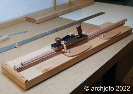
With the following pictures I illustrate the further processing steps in the yard production.
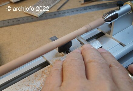

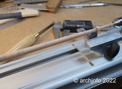


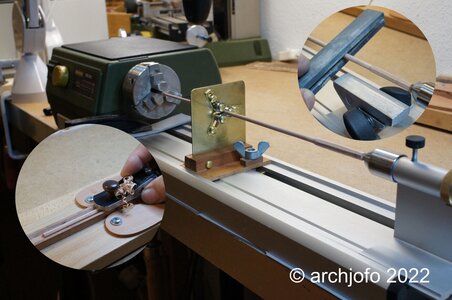
In contrast to the main yard, the studding sail booms are much more delicate logs with diameters of 3.7 to 2.2 mm, which had to be machined. So that this succeeds also without breakage, I built for this with simple means a small steady rest. With this I can bring small ball bearings for round timber with diameters of 1 - 10 mm into position for support. In the meantime, the small tool has already proven itself very well.
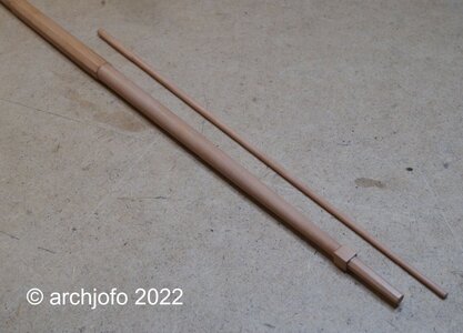
On the last picture you can see the first results.
To be continued ...
@dockattner
@RDN1954
@Jimsky
@shota70
@Peter Voogt
@Uwek
@Algol1957
@Hoss6262
@mtbediz1
Thank you very much.
I would also like to thank you for the many LIKES.
That makes me happy and raises the motivation.
Making the yards - Main yard - Grande vergue
Before starting to make the yards, I made myself a planing jig in advance, inspired by Ed Tosti's build report for the clipper "Young America" in the MSW, as shown in the drawing below. Rotating and locking clamps allow lumber of various widths and lengths to be fixed in place for machining, especially with a wood planer.

To make the main yard, I prepared a drawing with dimensions based on the plan by J. Boudriot.

The next two pictures show how the holding device mentioned at the beginning of the report can be used in practice.
It performs valuable services in the manufacture of yards. For example, a wooden strip with a V-shaped groove was clamped in place. A square timber inserted in this way can easily be planed into an octagonal timber. In this case for the main yard and later for the leeward spars. These timber blanks are then much easier to machine on the lathe. In addition, they are used to roughly preform the octagonal areas of the yards or studding sail booms.


With the following pictures I illustrate the further processing steps in the yard production.


In contrast to the main yard, the studding sail booms are much more delicate logs with diameters of 3.7 to 2.2 mm, which had to be machined. So that this succeeds also without breakage, I built for this with simple means a small steady rest. With this I can bring small ball bearings for round timber with diameters of 1 - 10 mm into position for support. In the meantime, the small tool has already proven itself very well.

On the last picture you can see the first results.

To be continued ...
Last edited:
Hello Johann,
Your craftmanship is magnificent and produced beautiful yards. I love your jig and the steady.
Bill
Your craftmanship is magnificent and produced beautiful yards. I love your jig and the steady.
Bill
Hello Johann, fabulous. Great work on the one hand and what I think is a very accurate description of your work in pictures and text on the other. Thanks for sharing. 

Your working jigs are more accurate than most of our ships .....
many thanks for sharing these information with us
many thanks for sharing these information with us
A wonderful clean result Johann. I especially admire half of the handiwork!! 


- Joined
- Nov 10, 2019
- Messages
- 479
- Points
- 373

@Bill-R
@Tobias
@Uwek
@shota70
@Ondras71
Hello,
I am very grateful for your interest and the nice comments, as well as for the many LIKES. That motivates immensely.
Continuation: Production of the yards - Vergues
We continued with the production of the yards. With the help of G. Delacroix I was able to clarify a few questions about the dimensions of the yards. Accordingly, I used the following table for the dimensions of the masts, yards and spars of the "La Blonde", which is identical in construction to the "La Créole".


Source: Monograph on La Créole by J. Boudriot, page 56
There, among other things, the diameters are given in addition to the lengths. As a rule, the small diameter of a yard is 2/5 of the large diameter, as I could learn from G. Delacroix.
As you can see on the following pictures, the lower yards with the studding sail booms have been made so far in the meantime. Various details on the yard arms, such as for the installation of sheaves for the sheets still require final clarification.


Also with the studding sail booms there are still questions about details, as shown in the following example of the model of the "Le Cotre 1830".
I would be very grateful for any suggestions and hints.
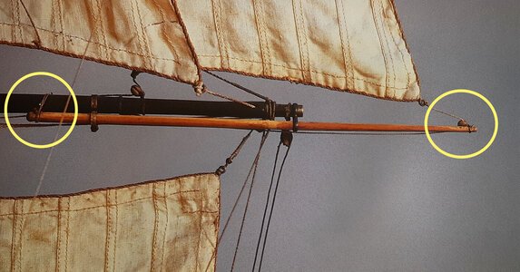
Source: Modèles Historiques au Musée de la Marine - Volume 2 - Jean Boudriot
To be continued ...
@Tobias
@Uwek
@shota70
@Ondras71
Hello,
I am very grateful for your interest and the nice comments, as well as for the many LIKES. That motivates immensely.
Continuation: Production of the yards - Vergues
We continued with the production of the yards. With the help of G. Delacroix I was able to clarify a few questions about the dimensions of the yards. Accordingly, I used the following table for the dimensions of the masts, yards and spars of the "La Blonde", which is identical in construction to the "La Créole".


Source: Monograph on La Créole by J. Boudriot, page 56
There, among other things, the diameters are given in addition to the lengths. As a rule, the small diameter of a yard is 2/5 of the large diameter, as I could learn from G. Delacroix.
As you can see on the following pictures, the lower yards with the studding sail booms have been made so far in the meantime. Various details on the yard arms, such as for the installation of sheaves for the sheets still require final clarification.


Also with the studding sail booms there are still questions about details, as shown in the following example of the model of the "Le Cotre 1830".
I would be very grateful for any suggestions and hints.

Source: Modèles Historiques au Musée de la Marine - Volume 2 - Jean Boudriot
To be continued ...
- Joined
- Nov 10, 2019
- Messages
- 479
- Points
- 373

Continuation: Making the yards - Fore topsail yard - Vergue de petit hunier
After making the lower yards, I started working on the topsail yards. In contrast to the yardarms of other navies in the comparable period, the ones of the French navy seem adventurous. Probably due to a higher flexibility of the sailing maneuvers, these topsails are a certain challenge for the modeler, as can be seen on the following pictures for the mizzen topsail -, fore topsail - and main topsail yard of the La Créole.

Source: Monograph La Creole by J. Boudriot
Unfortunately, I do not have sufficiently sharp images of the original model from which one could derive further details. So I rely on the plan drawing of the monograph except for the formation of the studding sail booms at the yards of the mizzen mast. For this I again follow the original model, which clearly shows no studding sail booms at the mizzen mast. Further research shows that many contemporary French models also do not have studding sail booms at the yards of the mizzen mast. John Harland in his book "Seamanship in the Age of Sail" writes about studding sails on the mizzen mast that in his opinion they were neither popular nor particularly practical.
After several attempts, the fore topsail yard seems to have succeeded according to the drawing specifications, at least I am satisfied.
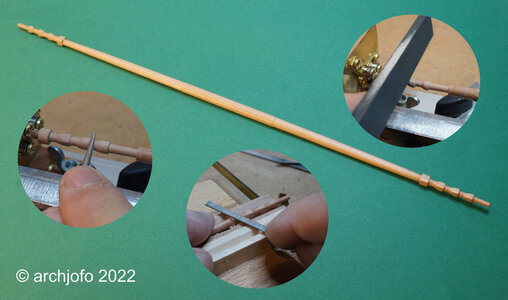
The next picture shows the fore topsail yard compared to the main yard, where the yard arm has a simpler design.

The drawing with dimensions for the main topsail yard is already available.
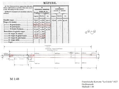
Soon it will go further ...
After making the lower yards, I started working on the topsail yards. In contrast to the yardarms of other navies in the comparable period, the ones of the French navy seem adventurous. Probably due to a higher flexibility of the sailing maneuvers, these topsails are a certain challenge for the modeler, as can be seen on the following pictures for the mizzen topsail -, fore topsail - and main topsail yard of the La Créole.

Source: Monograph La Creole by J. Boudriot
Unfortunately, I do not have sufficiently sharp images of the original model from which one could derive further details. So I rely on the plan drawing of the monograph except for the formation of the studding sail booms at the yards of the mizzen mast. For this I again follow the original model, which clearly shows no studding sail booms at the mizzen mast. Further research shows that many contemporary French models also do not have studding sail booms at the yards of the mizzen mast. John Harland in his book "Seamanship in the Age of Sail" writes about studding sails on the mizzen mast that in his opinion they were neither popular nor particularly practical.
After several attempts, the fore topsail yard seems to have succeeded according to the drawing specifications, at least I am satisfied.

The next picture shows the fore topsail yard compared to the main yard, where the yard arm has a simpler design.

The drawing with dimensions for the main topsail yard is already available.

Soon it will go further ...
Looks absolutey superb, top notch . Einfach spitzenmäßig.
- Joined
- Nov 10, 2019
- Messages
- 479
- Points
- 373

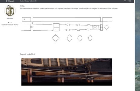
Hello,
Mr. G. Delacroix made the kind reference in the MSW, as seen above.
I obviously misinterpreted the drawing by J. Boudriot. Now following the hint I see that it only works graphically as an oval.
I also researched my picture collection again and found a picture of the Le Neptune 1836 from the Musée national de la Marine Paris. A yard can be seen there as a reserve, comparable to that of the Rivoli.
For a better overview I have included the drawings by J. Boudriot and G. Delacroix in this picture.
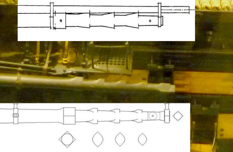
Source: Musée national de la Marine Paris, G. Delacroix, J. Boudriot
I also found a very interesting picture of a yardarm from the mizzen topsail yard of Le Sphinx 1829.
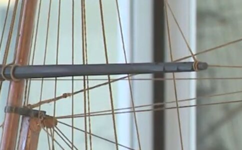
Source: Musée national de la Marine Paris
Will now try to make the yardarms of the topsail yards for the La Créole in the oval version according to the drawing by J. Boudriot.
I am very open and grateful for further hints and examples.
Very good to have helpful specialists bringing light to some details - good to know
I guess you can adjust your yardarms accordingly without making completely new ones
I guess you can adjust your yardarms accordingly without making completely new ones
- Joined
- Aug 8, 2019
- Messages
- 5,584
- Points
- 738

I don't think he will. "Pietje precies" (Piet exactly in English) will make new ones, I'm for sure.Very good to have helpful specialists bringing light to some details - good to know
I guess you can adjust your yardarms accordingly without making completely new ones
- Joined
- Nov 10, 2019
- Messages
- 479
- Points
- 373

@Uwek
@Steef66
I would like to thank you for your interest. That is fun and motivating.
I am extremely grateful to G. Delacroix for helping me again this time. That is not a matter of course. I have already decided that I will make new frames. Because there are still a few little things that don't quite fit. The problem at the moment is just how to connect Boudriot's information with the new findings. There are still many questions.
- Joined
- Oct 17, 2020
- Messages
- 1,691
- Points
- 488

Vorrei poterti aiutare in questo, ma il mio studio su queste navi è troppo scarso per fornire informazioni al riguardo. Ma vedo quanto sei preciso. E penso che troverai le tue risposte. Buona fortuna alla ricerca, cosa potrebbe essere tanto divertente quanto costruire.
@Uwek
@Steef66
Vorrei ringraziarvi per il vostro interesse. Questo è divertente e motivante.
Sono estremamente grato a G. Delacroix per avermi aiutato anche questa volta. Non è ovvio. Ho già deciso che realizzerò nuovi telai. Perché ci sono ancora alcune piccole cose che non si adattano del tutto. Il problema al momento è solo come collegare le informazioni di Boudriot con le nuove scoperte. Ci sono ancora molte domande.
spero di fareView attachment 341020
Ciao,
Il signor G. Delacroix ha fatto il riferimento gentile nella RSU, come visto sopra.
Ovviamente ho interpretato male il disegno di J. Boudriot. Ora seguendo il suggerimento vedo che funziona solo graficamente come un ovale.
Ho anche cercato di nuovo la mia collezione di quadri e ho trovato un'immagine del Le Neptune 1836 dal Musée national de la Marine Paris. Vi si vede un cantiere di riserva, paragonabile a quello dei Rivoli.
Per una migliore visione d'insieme ho inserito in questa immagine i disegni di J. Boudriot e G. Delacroix.
View attachment 341021
Fonte: Musée national de la Marine Paris, G. Delacroix, J. Boudriot
Ho anche trovato un'immagine molto interessante di un pennone del pennone di mezzana di Le Sphinx 1829.
View attachment 341022
Fonte: Musée national de la Marine Paris
Proverò ora a realizzare i pennoni dei pennoni di gabbia per La Créole nella versione ovale secondo il disegno di J. Boudriot.
Sono molto aperto e grato per ulteriori suggerimenti ed esempi.
benvenuto cosa con questo documento

Last edited:
- Joined
- Nov 10, 2019
- Messages
- 479
- Points
- 373

Continued: Clarifying the yardarms
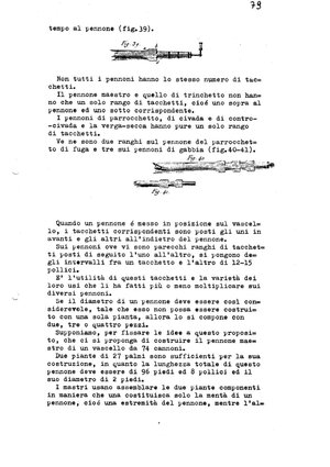
After an extensive web search I came across this book: "Description de l'art de la Mâture" (published in 1778) by Charles Nicolas Romme.
Below are excerpts of the yardarms: Fig. 38 clearly explains the "oval" cross-sections in the area of the cleats on the yardarms.

In connection with the design of the yardarms for the La Créole, the question of the chronological classification naturally arises: The Le Rivoli is from 1810, the Le Sphinx from 1829 and the Le Neptune from 1836. In this respect, this is for the epoch of the La Créole applicable.
Apparently I'm not the only one who stumbled across this problem. So thanks again to G. Delacroix who gave me the crucial hint.
For my model, however, the question now arises as to how I can reconcile this detail with the drawings by J. Boudriot. I would prefer to stick to the original model. Unfortunately I don't have any meaningful detailed pictures. Ultimately, I will have to make a decision about this detailed design, even with the risk that it will not be entirely correct.
After an extensive web search I came across this book: "Description de l'art de la Mâture" (published in 1778) by Charles Nicolas Romme.
Below are excerpts of the yardarms: Fig. 38 clearly explains the "oval" cross-sections in the area of the cleats on the yardarms.

In connection with the design of the yardarms for the La Créole, the question of the chronological classification naturally arises: The Le Rivoli is from 1810, the Le Sphinx from 1829 and the Le Neptune from 1836. In this respect, this is for the epoch of the La Créole applicable.
Apparently I'm not the only one who stumbled across this problem. So thanks again to G. Delacroix who gave me the crucial hint.
For my model, however, the question now arises as to how I can reconcile this detail with the drawings by J. Boudriot. I would prefer to stick to the original model. Unfortunately I don't have any meaningful detailed pictures. Ultimately, I will have to make a decision about this detailed design, even with the risk that it will not be entirely correct.


