
-

SUBSCRIBE TO SHIPS IN SCALE TODAY!
The beloved Ships in Scale Magazine is back and charting a new course for 2026!
Discover new skills, new techniques, and new inspirations in every issue.
NOTE THAT OUR NEXT ISSUE WILL BE MARCH/APRIL 2026 -

Win a Free Custom Engraved Brass Coin!!!
As a way to introduce our brass coins to the community, we will raffle off a free coin during the month of August. Follow link ABOVE for instructions for entering.
You are using an out of date browser. It may not display this or other websites correctly.
You should upgrade or use an alternative browser.
You should upgrade or use an alternative browser.
La Créole 1827 by archjofo - Scale 1/48 - French corvette
- Joined
- Aug 8, 2019
- Messages
- 5,743
- Points
- 738

Yes the only strange thing on it. I search on Google and found this pictureIsn't it too far down for a lamp?

And looking further on that picture there is also a document available to download.
Master Class 1 | PDF | Compass | Force
Scribd is the world's largest social reading and publishing site.
- Joined
- Aug 8, 2019
- Messages
- 5,743
- Points
- 738
I discover this free link about the working of these compass pdf download
- Joined
- Oct 17, 2020
- Messages
- 1,759
- Points
- 488

see what i found in my paperworkIsn't it too far down for a lamp?
.jpeg")
.jpeg")


- Joined
- Nov 10, 2019
- Messages
- 520
- Points
- 453

@Steef66
Many Thanks, for the really informative documentation. They are very helpful.
@Frank48
Many thanks to you too for the very instructive book excerpts.
Everything is explained there in great detail.
After seeing and reading all this, I'm becoming more and more aware that this is a flinders bar.
Many Thanks, for the really informative documentation. They are very helpful.
@Frank48
Many thanks to you too for the very instructive book excerpts.
Everything is explained there in great detail.
After seeing and reading all this, I'm becoming more and more aware that this is a flinders bar.
Last edited:
- Joined
- Nov 10, 2019
- Messages
- 520
- Points
- 453
Maybe the compass question can still be solved,
in the meantime things will continue with the yards:
Continued: Making the yards - main topsail yard - Vergue de grand hunier
For long enough I evaded the decision to execute the yardarms of the main topsail yard. Further research on this did not bring any new findings.
Now that the holidays are over and with renewed vigor in the new year, I have decided on the following embodiment of the yardarms of the topsail yards, as already signaled in one of the last posts:

So now we can continue with the production of the yards.
Sequel follows …
- Joined
- Aug 8, 2019
- Messages
- 5,743
- Points
- 738
I found a Dutch document, free to download, about ship navigation. Don't know if you can read or translate it. But there is a lot of information about navigation of ships. And also a lot of information how these compass with correction works. Maybe more information for you to study. To create the compass that fit more in time and construction to your ship. Like the sphere on each side of the compass. The magnets inside the wooden part below the compass housing to calibrate the compass. Details to show.

 docplayer.nl
Navigeren in de negentiende eeuw - PDF Free Download
Navigeren in de negentiende eeuw Aan de vooravond van een nieuwe eeuw Navigatie, en dan in t bijzonder de plaatsbepaling van een vaartuig op zee, was en is nog altijd een heikel probleem voor de scheepvaart.

Happy New Year to you too Johann.
- Joined
- Nov 10, 2019
- Messages
- 520
- Points
- 453
Hello,
On the subject of compass, the discussion in the MSW also considered the possibility that a lamp could also be attached below the compass rose. The documents from @Frank48 obviously also show this and in this respect I am unsure again. Should the compass of La Creole actually have been a lamp? Because actually the compass should have been illuminated, right?
On the subject of compass, the discussion in the MSW also considered the possibility that a lamp could also be attached below the compass rose. The documents from @Frank48 obviously also show this and in this respect I am unsure again. Should the compass of La Creole actually have been a lamp? Because actually the compass should have been illuminated, right?
- Joined
- Aug 8, 2019
- Messages
- 5,743
- Points
- 738
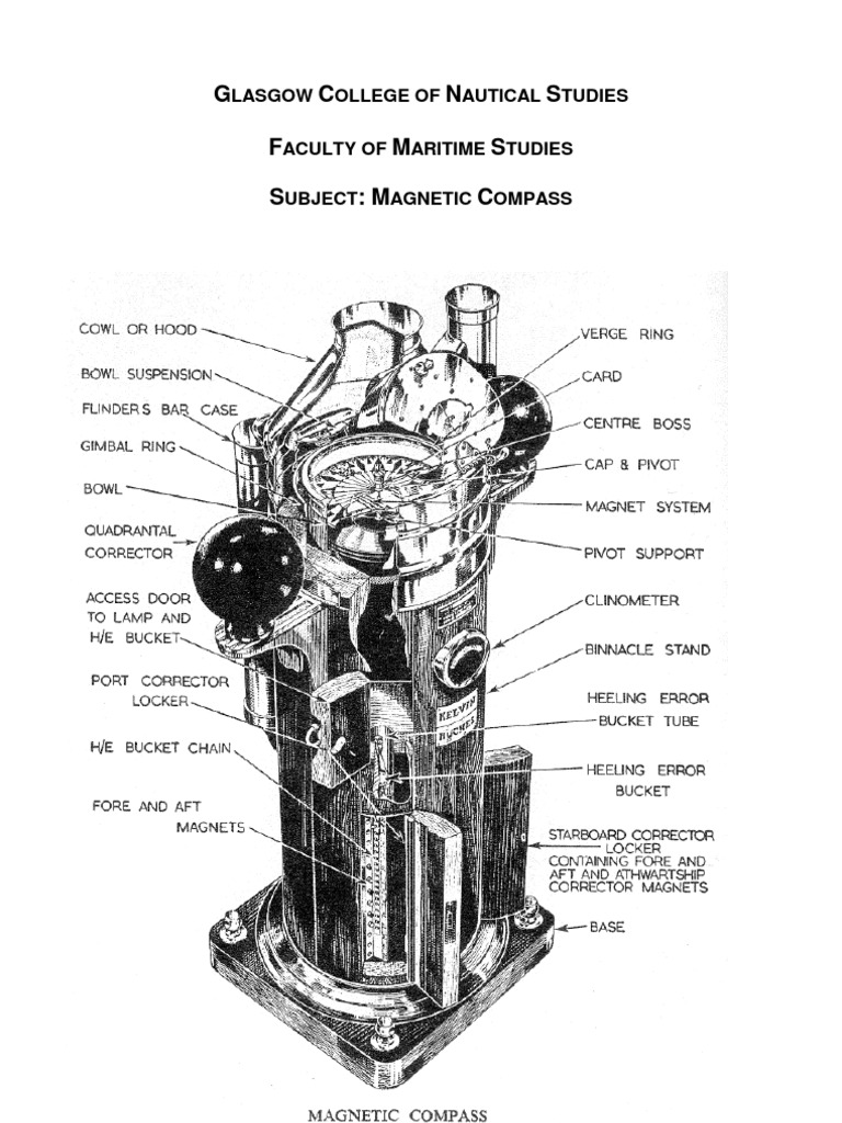
your ship is of 1827. In that time there where already a lot of correctors attached. The compass shown on the model is an exact copy of the compass in real or is this a simplify version of it? Did the La Creole of 1827 be equipped with a compass that contains only a light on the side? Or should the compass not be more looking like a version of below picture?

I translated a part of the last link I gave about the Dutch document. The flinders bar was an invention of Captain Flinder and would be in my opinion a part of the compass in that time. The magnets in the wooden part and the spheres on both sides could be from a later time.
How do you think about this theory?
Attachments
I went through your log for the first time. Excellent accurate work !
- Joined
- Nov 10, 2019
- Messages
- 520
- Points
- 453
@Steef66
Hello Stephan,
the plans of La Creole are dated 1827. The corvette was launched in 1829 and commissioned in 1830. I assume that the compass on the original Paris model was very detailed and corresponded to the state of the art at the time.
It also shows this part, which is the subject of this discussion. I think the La Creole's compass wasn't as sophisticated as the one you show in the picture.
This appears to be a modern compass.
In my starting position in #318, I presented the two options for the part under discussion - Flinders bar - lamp I had my doubts about the Flinders bar, since it is a wooden ship, and about the lamp it was the low mounting, below the wind rose.
But obviously the binnacles also had lower lamps, as can also be seen in your documents in #324. A fellow German model builder found another compass in the NMM archives that seems relevant in this context. The downside is that they date from the 1930s!
LINK
So it would be quite conceivable that this is a lamp, especially since a compass without lighting is not necessarily an advantage.
But that does not yet give security for a correct statement.
- Joined
- Aug 8, 2019
- Messages
- 5,743
- Points
- 738
Like I first suggested. And the brass is just a cap on the compass to protect it. The compass is actually in the wooden part. I seen somewhere a construction like that. It is highly possible that this ship doesn't have the need of a flinders bar.@Steef66
Hello Stephan,
the plans of La Creole are dated 1827. The corvette was launched in 1829 and commissioned in 1830. I assume that the compass on the original Paris model was very detailed and corresponded to the state of the art at the time.
It also shows this part, which is the subject of this discussion. I think the La Creole's compass wasn't as sophisticated as the one you show in the picture.
This appears to be a modern compass.
In my starting position in #318, I presented the two options for the part under discussion - Flinders bar - lamp I had my doubts about the Flinders bar, since it is a wooden ship, and about the lamp it was the low mounting, below the wind rose.
But obviously the binnacles also had lower lamps, as can also be seen in your documents in #324. A fellow German model builder found another compass in the NMM archives that seems relevant in this context. The downside is that they date from the 1930s!
LINK
So it would be quite conceivable that this is a lamp, especially since a compass without lighting is not necessarily an advantage.
But that does not yet give security for a correct statement.
- Joined
- Nov 10, 2019
- Messages
- 520
- Points
- 453
Hello colleagues,
I am still completing the detail on the compass later.
Continuation: Making the yards - Topgallant yards - Vergue de perroquet
After the topsail yards, we continued with the making of the topgallant yards.
Here is a quick look at my workplace with the most important utensils for making the yards:

The diameters of the topgallant yards, especially in the outer sections, range around 1.6 mm. In this respect, it is not surprising, if you work without a steady rest, that it can sometimes come to breakage.

At the latest when working on the yardarms, it is advisable to support the filigree yards with a steady rest.

The next picture shows the finishing of the octagon in the center of the yardarm.

The last picture should give an impression of how filigree the topgallant yards are compared to the lower yards. It shows the yardarms of the main yard compared to the mizzen topgallant yard. The octagon of the yardarm of the mizzen topgallant yard still has a width of 1.3 mm at the outer end.

Of course, the royal yards can be made even thinner and more filigree. Especially the octagonal shaping at the yardarms requires special care.
To be continued ...
I am still completing the detail on the compass later.
Continuation: Making the yards - Topgallant yards - Vergue de perroquet
After the topsail yards, we continued with the making of the topgallant yards.
Here is a quick look at my workplace with the most important utensils for making the yards:
The diameters of the topgallant yards, especially in the outer sections, range around 1.6 mm. In this respect, it is not surprising, if you work without a steady rest, that it can sometimes come to breakage.
At the latest when working on the yardarms, it is advisable to support the filigree yards with a steady rest.
The next picture shows the finishing of the octagon in the center of the yardarm.
The last picture should give an impression of how filigree the topgallant yards are compared to the lower yards. It shows the yardarms of the main yard compared to the mizzen topgallant yard. The octagon of the yardarm of the mizzen topgallant yard still has a width of 1.3 mm at the outer end.
Of course, the royal yards can be made even thinner and more filigree. Especially the octagonal shaping at the yardarms requires special care.
To be continued ...
I am a little bit jealous about your beautiful tools - "helpers"
Many Thanks for the insight and view on your working table
So cool
Many Thanks for the insight and view on your working table
So cool
- Joined
- Nov 10, 2019
- Messages
- 520
- Points
- 453
Continuation: Making the topgallant yards - Vergue de cacatois
In the meantime, I have started making the topgallant yards. As already written in the last report, the topgallant yards are even thinner and more filigree, like the topsail yards.
The dimensions from the plan documents of J. Boudriot were again compared by me with the data of a contemporary original document. This table shows the dimensions of the masts and yards of the La Blonde, which is identical in construction to the La Créole. All dimensions corresponded to the drawings, as is clearly shown in the following drawing.

I have already noted that with these dimensions at ø 1.4 mm it is no longer feasible without a steady rest. A toothpick, for example, has a diameter of 1.8 mm. In this respect, particular care should be taken here and not too much pressure should be exerted on the roundwood.

The shaping of the square edge with the octagonal yardarm also requires sensitive processing, which can be seen in the next picture.

At the end of this work, a comparison of yardarms:
Main yard, mizzen toppsail yard and mizzen topgallant yard

Now two lower studding sail booms have to be made to hang on the fore channels.
With the gaff (upper spar) and the driver boom (lower boom) already made some time ago, all the sail-carrying spars for the French corvette are then ready. They will then be equipped with the necessary fittings (sheaves, boom irons, etc.).
To be continued ...
In the meantime, I have started making the topgallant yards. As already written in the last report, the topgallant yards are even thinner and more filigree, like the topsail yards.
The dimensions from the plan documents of J. Boudriot were again compared by me with the data of a contemporary original document. This table shows the dimensions of the masts and yards of the La Blonde, which is identical in construction to the La Créole. All dimensions corresponded to the drawings, as is clearly shown in the following drawing.
I have already noted that with these dimensions at ø 1.4 mm it is no longer feasible without a steady rest. A toothpick, for example, has a diameter of 1.8 mm. In this respect, particular care should be taken here and not too much pressure should be exerted on the roundwood.
The shaping of the square edge with the octagonal yardarm also requires sensitive processing, which can be seen in the next picture.
At the end of this work, a comparison of yardarms:
Main yard, mizzen toppsail yard and mizzen topgallant yard
Now two lower studding sail booms have to be made to hang on the fore channels.
With the gaff (upper spar) and the driver boom (lower boom) already made some time ago, all the sail-carrying spars for the French corvette are then ready. They will then be equipped with the necessary fittings (sheaves, boom irons, etc.).
To be continued ...
Johann,
Great!!!
Very nice and clean work! Sorry , what is the name of the wood which You work with ? (at this stage)
All The Best
Kirill
Great!!!
Very nice and clean work! Sorry , what is the name of the wood which You work with ? (at this stage)
All The Best
Kirill
You are making some excellent pieces on your lathe, Johan. Very very nice.Continuation: Making the topgallant yards - Vergue de cacatois
In the meantime, I have started making the topgallant yards. As already written in the last report, the topgallant yards are even thinner and more filigree, like the topsail yards.
The dimensions from the plan documents of J. Boudriot were again compared by me with the data of a contemporary original document. This table shows the dimensions of the masts and yards of the La Blonde, which is identical in construction to the La Créole. All dimensions corresponded to the drawings, as is clearly shown in the following drawing.
View attachment 353086
I have already noted that with these dimensions at ø 1.4 mm it is no longer feasible without a steady rest. A toothpick, for example, has a diameter of 1.8 mm. In this respect, particular care should be taken here and not too much pressure should be exerted on the roundwood.
View attachment 353083
The shaping of the square edge with the octagonal yardarm also requires sensitive processing, which can be seen in the next picture.
View attachment 353084
At the end of this work, a comparison of yardarms:
Main yard, mizzen toppsail yard and mizzen topgallant yard
View attachment 353085
Now two lower studding sail booms have to be made to hang on the fore channels.
With the gaff (upper spar) and the driver boom (lower boom) already made some time ago, all the sail-carrying spars for the French corvette are then ready. They will then be equipped with the necessary fittings (sheaves, boom irons, etc.).
To be continued ...
Regard, Peter