La Créole 1827 by archjofo - Scale 1/48 - French corvette

@Peter Voogt
Hi Peter,
thank you for your nice comment. That's good for my motivation.

Completion: Yards and spars
With the production of the lower studding sail booms, which are attached to the fore-channels, I could finish the chapter yards/spars for my corvette.
So I had to show all the spars in their entirety, as you can see below:
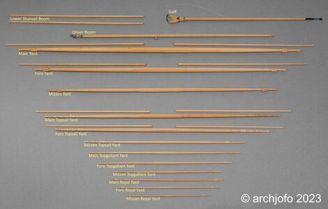
DSC00866.jpg
This completes the woodwork on this model except for more blocks and a few odds and ends.
I am currently researching the studding sail boom iron, among other things. Also for this there is a multiplicity of variants, which are to be evaluated and classified chronologically correctly. The monograph of J. Boudriot leaves some questions open.
See you soon ...
 
Only when you show all of the yards and spars on one place you realize how much of them a realtively small ship had in use
Highly interesting overview - many thanks for showing us
and congrats for finishing the wooden works - you will miss it
 
Hello Johann, very impressive work. As I find these pictures and information are always very important. I had already talked with Oliver @Olivers Historic Shipyard about it that it is often a pity that in many construction protocols you do not see the way to the result and also the explanation is missing. Besides the excellent work, it is also what I appreciate very much with you.
 
@Tobias
Hello Tobias,
thank you for your approval. But in this case I deviated a bit, since I reported on the compass in more detail a long time ago. This is ultimately a matter of adding a detail.

Continued: ship's compass
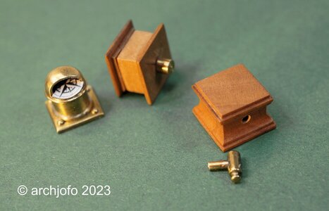
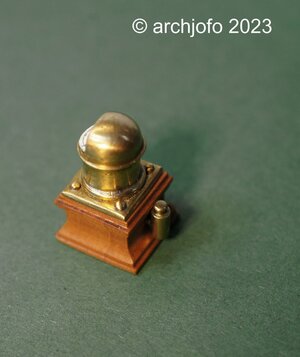
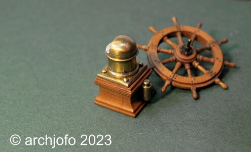
Some time ago I was concerned with the question of what the part at the back of the binnacle of the La Créole is. There is much to be said for a soft iron corrector, the so-called flinders bar. Lighting would also be conceivable based on the shape. The discussion, including in the SOS, does not yield a clear result. After I got to see historical compass housings in the meantime, where the lighting was arranged below the compass rose, I personally tend to think that this could have been a lamp. Also because of the fact that this corvette was a wooden ship, i.e. had little iron to influence the compass, and on the other hand lighting seems to be quite useful and necessary. In the end I can't say for sure. So I decided to just build this thing and leave it up to the viewer what he thinks it is. On this occasion I revised the compass and remade the wooden case. The lamp ? or the soft iron corrector? was made from a round brass rod ø 1.5 mm analogous to the photos of the Paris model available to me.
DSC00876.jpg

DSC00879.jpg


DSC00881.jpg

Sequel follows …
 
wonderful detail - and also outstanding execution
and I guess the compass is really small -> BRAVO
 
Equipping the yards
In the meantime, I have started to fit the ends of the yards with sheaves, over which the sheets and reef tackles are then passed.
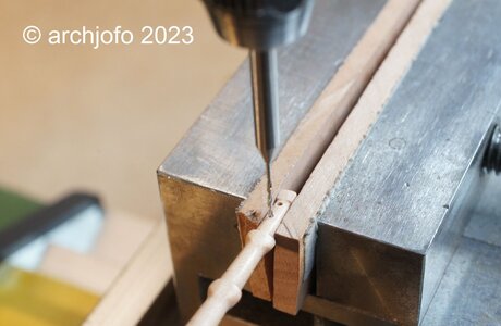
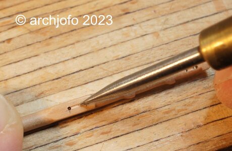
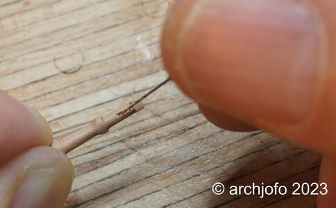
In the lower and topsail yards, the holes for sheave were made with the 0.8 mm and 0.6 mm milling cutter, with the exception of the mizzen topsail yard. Brass turned sheaves will be installed there later.
For the topgallant and royal yards with the mizzen topsail yard, the sheaves are only suggested due to the size. The following pictures show the individual processing steps.

1. drill holes with 0.5 mm
DSC00887.jpg

2. finishing with 0.5 mm wood hollow chisel
DSC00890.jpg

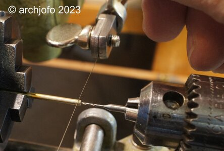
3. rounding out with 0.5 mm shank drill bit
DSC00888.jpg

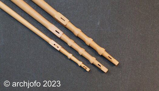
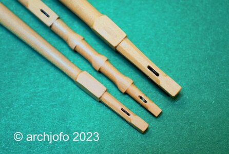
The last picture shows the yard arms of the main topsail, fore topsail and mizzen topsail yard.
DSC00898.jpg

I think that the "fake" sheaves in the mizzen topsail yard are reasonably convincing. I have also used the same method on many blocks.
See you soon ...
 
@Mirek
Hello,
thank you for your interest in my construction report and the appreciation of my work.
Many thanks also to the others for the many LIKES.

Continued: Equipment of the yards
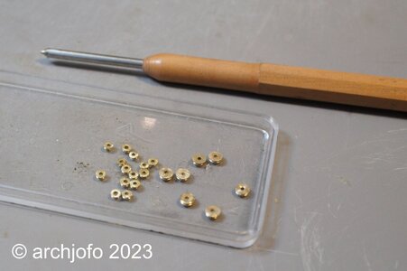
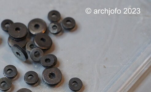
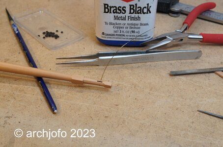
As announced in the last part of my construction report, I equip the larger yards with real discs. As before, I make these discs out of brass and blue them. As far as I know, these discs were usually made of lignum vitae. The rather dark brown coloring of this wood can be easily imitated with a blue finish.
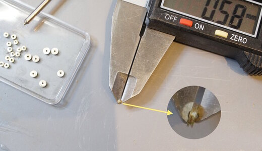
For the main yard and the fore yard, the sheaves have a diameter of 2.9 mm. The main topsail yard, fore topsail yard and mizzen yard are fitted with sheaves with a diameter of 2.0 mm.
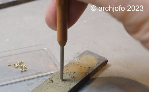
With the following series of pictures I would like to illustrate how I make the sheaves. Since my turning skills are limited and with these small diameters, I made the circular groove with a jeweller's saw. The fine saw blade I use for this has a thickness of 0.15 mm. I can control the width of the groove. The more inclined I lead the saw blade, the wider the groove. As a rule, the groove has a width of around 0.2 mm.
DSC00901.jpg


After cutting the sheaves, I grind them to the required thickness according to the size of the protrusion for the sheaves, i. H. about ø 0.6 mm or 0.8 mm. For grinding, I made myself an aid, the tip of which engages in the axle hole and thus enables the sheaves to be guided more or less evenly for grinding.
DSC00903.jpg

DSC00905.jpg

DSC00906.jpg

The axle bores of the sheaves were made with ø 0.8 mm larger than the axle diameter ø 0.4 mm itself. This makes the installation of the sheaves much easier and also compensates for small inaccuracies.
DSC00907.jpg

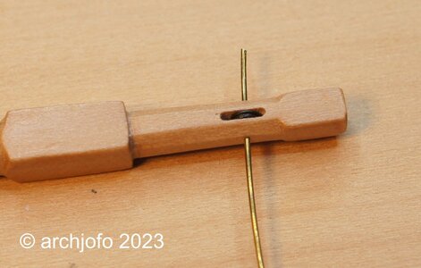
The next pictures should give an impression of the installation of the sheaves. As can be seen in the second picture, the axle holes are not exactly opposite. This is due to the fact that I have to drill the ø 0.4 mm holes for the axles from each side. If you try to drill these holes in one go from one side, it can easily happen that the hole on the other side does not arrive in the middle due to the thin drill and other inaccuracies. This is then much more disturbing than the axis points that are not exactly opposite, which is no longer noticeable after the shortening anyway.
DSC00908.jpg

DSC00909.jpg

After shortening the axles, the ends are filed clean with a micro file and blued. The filing creates a small burr, which usually makes it no longer necessary to glue the axles.
The last picture shows the finished yardarms of the fore yard, main yard and mizzen yard.
DSC00912.jpg

It then continues with the stunsail boom irons. There are still a few open points to be clarified, as always...
Sequel follows …
 
@Mirek
Hello,
thank you for your interest in my construction report and the appreciation of my work.
Many thanks also to the others for the many LIKES.

Continued: Equipment of the yards
As announced in the last part of my construction report, I equip the larger yards with real discs. As before, I make these discs out of brass and blue them. As far as I know, these discs were usually made of lignum vitae. The rather dark brown coloring of this wood can be easily imitated with a blue finish.
For the main yard and the fore yard, the sheaves have a diameter of 2.9 mm. The main topsail yard, fore topsail yard and mizzen yard are fitted with sheaves with a diameter of 2.0 mm.
With the following series of pictures I would like to illustrate how I make the sheaves. Since my turning skills are limited and with these small diameters, I made the circular groove with a jeweller's saw. The fine saw blade I use for this has a thickness of 0.15 mm. I can control the width of the groove. The more inclined I lead the saw blade, the wider the groove. As a rule, the groove has a width of around 0.2 mm.
View attachment 356339


After cutting the sheaves, I grind them to the required thickness according to the size of the protrusion for the sheaves, i. H. about ø 0.6 mm or 0.8 mm. For grinding, I made myself an aid, the tip of which engages in the axle hole and thus enables the sheaves to be guided more or less evenly for grinding.
View attachment 356340

View attachment 356341

View attachment 356342

The axle bores of the sheaves were made with ø 0.8 mm larger than the axle diameter ø 0.4 mm itself. This makes the installation of the sheaves much easier and also compensates for small inaccuracies.
View attachment 356343

The next pictures should give an impression of the installation of the sheaves. As can be seen in the second picture, the axle holes are not exactly opposite. This is due to the fact that I have to drill the ø 0.4 mm holes for the axles from each side. If you try to drill these holes in one go from one side, it can easily happen that the hole on the other side does not arrive in the middle due to the thin drill and other inaccuracies. This is then much more disturbing than the axis points that are not exactly opposite, which is no longer noticeable after the shortening anyway.
View attachment 356344

View attachment 356345

After shortening the axles, the ends are filed clean with a micro file and blued. The filing creates a small burr, which usually makes it no longer necessary to glue the axles.
The last picture shows the finished yardarms of the fore yard, main yard and mizzen yard.
View attachment 356346

It then continues with the stunsail boom irons. There are still a few open points to be clarified, as always...
Sequel follows …
That is looking very nice, Johann. Showing the proces as well as the outcome. I think your motto is: Size does matters! Boundaries are there to be pushed.:)
Regards, Peter
 
@Steef66
@pianoforte
@Mirek
@shota70
@Peter Voogt

Hello,
I would like to thank you very much for the interest and the nice comments. Also to all the others a thank you for the many LIKES.


Continuation: Equipping the yards - studding sail boom irons
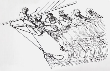
Since I am also interested in how studding sail booms work, that is, how to deploy and attach them, I tried to find more information in the relevant literature and on the Internet. In particular, the book "Seamanship in the Age of Sail" by John Harland describes, among other things, the handling of studding sail booms. This naturally results in various details on the spars themselves (of which later) and in this case on the studding sail boom irons.

Seamanship_John_Harland_S.147.jpg
Source: Seamanship in the Age of Sail, John Harland, p. 147

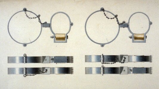
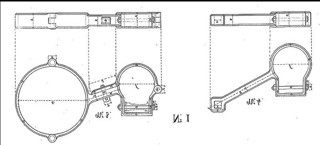
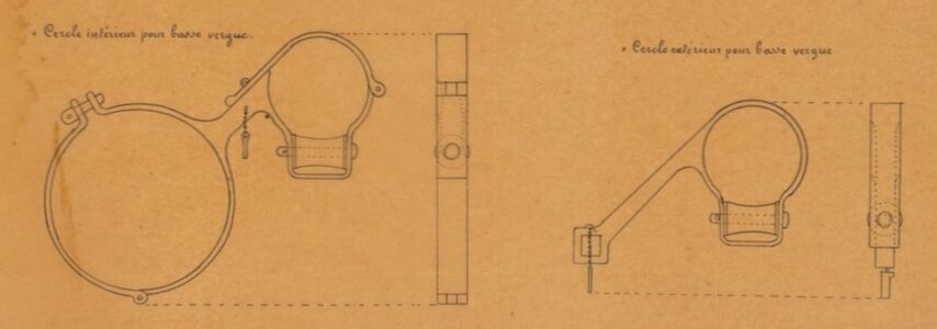
The preceding picture from this book explains very impressively that the studding sail booms, which were a handicap when sailing, were taken up and attached to the shrouds. To make this possible, the inside boom irons were hinged to open, which can also be seen in the contemporary drawings below. As can also be seen, these examples have different angles, depending on their chronological placement. This also corresponds with the observations of the photographs of contemporary ship models of the Musée national de la Marine.

cercle11.jpg
Source: Internet_MSW_Archives_G. Delacroix_ca.1830

AtlasDuGenieMaritime_Brest_1850.jpg
Source: Atlas_Brest_1850

ATLAS_Toulon_1854.jpg
Source: Atlas_Toulon_1854

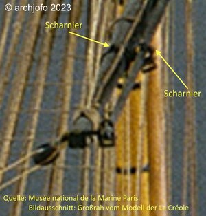
As mentioned before, the Paris Museum has kindly provided me with a high-resolution overall image of La Créole, from which I can obtain additional information to Jean Boudriot's monograph. Especially in the case of the studding sail booms, it can be seen that they were clearly arranged in front of the yard, without angles as shown in the monograph. This also corresponds to the temporal context.
In this respect I orientate myself for my model on the drawing, which I received thankfully from G. Delacroix via MSW. Similarities between this drawing and the original Paris model, as shown below, are clearly recognizable. Also I see there the already described details on the historical drawings confirmed.
MuseumParis_LaCreole_Großrahausschnitt.jpg

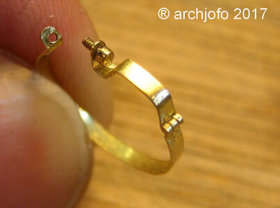
Now I will get to work on the realization for the model. I hope to find a way to produce these difficult details as far as possible. A special challenge is the mounting of the inside studding sail boom iron, because I have to choose a two-piece design for it due to the expansions at the yard arms, if possible with hinges like on the original. I have already made comparable hinges for this model as attachment for the front fishes. But this time it has to go one size smaller.
IMG_0984.jpg

I decided to make the studding sail boom irons for the fore topsail yard first, because they have the smallest dimensions.
Bigger is always possible...

More about that soon ...
 
Continuation: Equipping the yards - studding sail boom irons
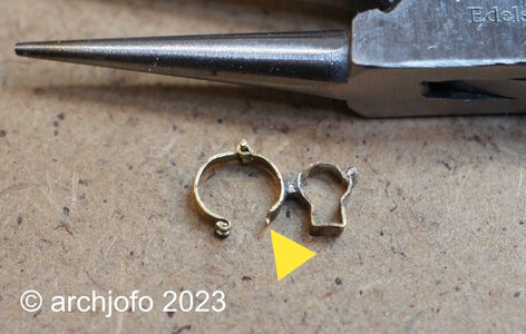
After initial problems and a failed attempt, I set out with new courage to make another one. Probably to avoid the mistakes of the first attempt, such as brazing the fine parts of the hinges too much heat, so that they then ultimately become brittle and break off (see picture). In principle, it would also have been possible to make these joints with soft solder. However, for reasons of strength, I chose brazing.
DSC00914.jpg

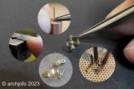
On the next picture I show a photo collage, where single steps for making the studding sail boom iron are shown.
DSC00935.jpg

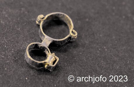
On the next picture you can see the studding sail boom iron still in uncleaned condition after brazing. The outer ring is still missing the hint of a hinge, which I will fix with soft solder.
DSC00933.jpg

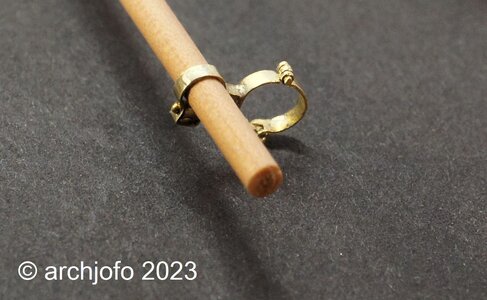
Here a picture with spar:
DSC00937.jpg

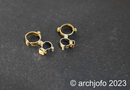
And finally the result for the two inner studding sail boom irons of the fore topsail yard.
DSC00944.jpg

Making the outer studding sail boom irons should be much easier.
To be continued ...
 
Back
Top