La Créole 1827 by archjofo - Scale 1/48 - French corvette

Good morning Johann quick question about the above book title, is this the right book?

View attachment 423566
Take a look into the review:
 
Hello Tobias,
Hello friends,

I've only read it now.
But you have already clarified everything. Thanks!
The book is really recommended. Many details for a rigging are included there.
Of course, you always have to check in each individual case whether this is appropriate for your model in terms of time and country.
 
Continuation: Equipping the main topgallant yard - Vergue de grand perroquet

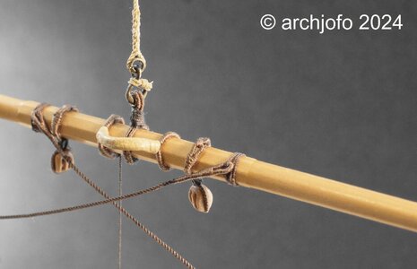
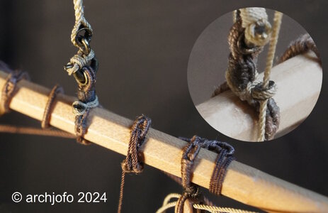
Once I had clarified the details for the footropes with the stirrups, it was time for the implementation. Thanks to the corresponding preliminary work on a test piece, the stirrups were attached to the yard quickly and without any problems.
Before the eye splices of the footropes could be pulled over the yardarms, the prepared grommets were first put on as chafe protection.
DSC01797.jpg

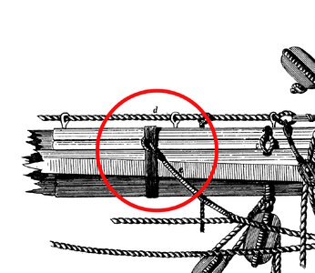
When attaching the footropes in the center of the yard, I used the following example as a guide.
Freiherr_Sterneck_Takelung_und_Ankerkunde_Fußpferd_Befestiguhng.jpg
Source: Freiherr v. Sterneck, "Takelung und Ankerkunde", 1873

This is what the realization for the model looks like:
DSC01799.jpg

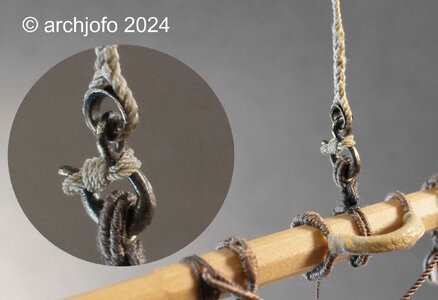
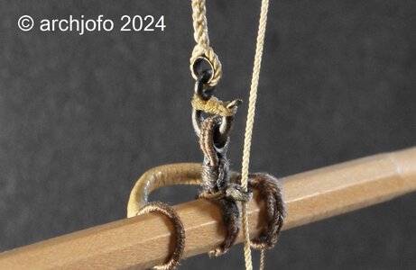
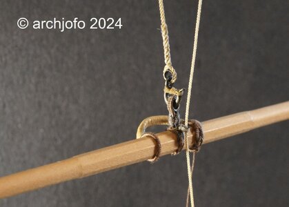
I have now also made the mousing to secure the hook for the tye:
DSC01801.jpg

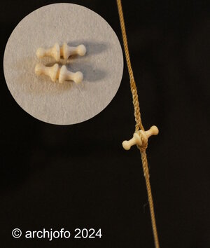
The simple buntlines were guided in thimbles at the topgallant yards of the French corvette. These buntlines branched out in the lower area onto two ropes, which were attached to the leeches of the sail. I therefore attached a thimble directly to the tye, as seen on the original Parisian model.
DSC01815.jpg

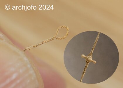
The clewlines for the topgallant sails were normally connected to the clews by means of toggles. Without sails, the clewlines are connected directly to the topgallant sheets.
DSC01811.jpg

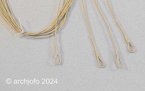
The single-guided lifts, the braces attached directly with eye splices and the aforementioned sheets complete the equipment of the main topgallant yard. These ropes have a diameter of ø 0.25 mm and served eye splices for laying on the yardarms.
DSC01820.jpg

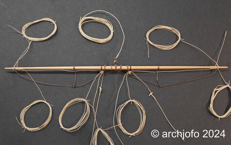
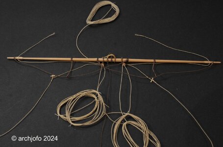
The last two pictures give an overview of the main topgallant yard with all equipment elements and ropes.
DSC01825.jpg

DSC01827.jpg
I will continue with the fore topgallant yard.

More about that soon ...
 
Last edited:
Continuation: Equipping the main topgallant yard - Vergue de grand perroquet

Once I had clarified the details for the footropes with the stirrups, it was time for the implementation. Thanks to the corresponding preliminary work on a test piece, the stirrups were attached to the yard quickly and without any problems.
Before the eye splices of the footropes could be pulled over the yardarms, the prepared grommets were first put on as chafe protection.
View attachment 424130

When attaching the footropes in the center of the yard, I used the following example as a guide.
View attachment 424140
Source: Freiherr v. Sterneck, "Takelung und Ankerkunde", 1873

This is what the realization for the model looks like:
View attachment 424133

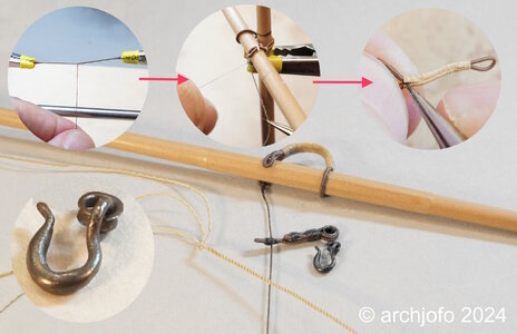
I have now also made the mousing to secure the hook for the tye:
View attachment 424144

The simple buntlines were guided in thimbles at the topgallant yards of the French corvette. These buntlines branched out in the lower area onto two ropes, which were attached to the leeches of the sail. I therefore attached a thimble directly to the tye, as seen on the original Parisian model.
View attachment 424141

The clewlines for the topgallant sails were normally connected to the clews by means of toggles. Without sails, the clewlines are connected directly to the topgallant sheets.
View attachment 424135

The single-guided lifts, the braces attached directly with eye splices and the aforementioned sheets complete the equipment of the main topgallant yard. These ropes have a diameter of ø 0.25 mm and served eye splices for laying on the yardarms.
View attachment 424143

The last two pictures give an overview of the main topgallant yard with all equipment elements and ropes.
View attachment 424138

View attachment 424139
I will continue with the fore topgallant yard.

More about that soon ...
As before, outstanding rope work, Johann.
Regards, Peter
 
Witaj
I znowu nie pozostało mi nic innego jak napisać cudownie piękna praca, próbuję się wzorować na twojej pracy bo jesteś wzorem do naśladowania dla mnie i pewnie dla wielu kolegów na naszym forum. Pozdrawiam Mirek

Hello
And again, I had no choice but to write a wonderfully beautiful piece of work. I try to follow your example because you are a role model for me and probably for many colleagues on our forum. Regards, Mirek
 
Last edited by a moderator:
@Peter Voogt
@Mirek
@Uwek
Thank you very much for your interest and the nice comments. Of course also thanks for the LIKES.


Hello dear colleagues,

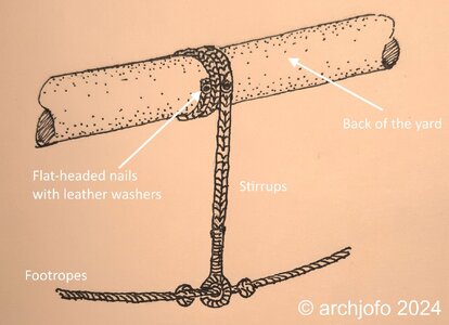
I wanted to provide an additional explanation about the braided stirrups.
In various publications I was able to read how the braids were looped and secured around the yards, but I have not yet found a picture of it. According to these descriptions, I implemented it for my model at the main topgallant yard and quickly made a sketch at the request of a colleague.
I think it might have looked like this:

footropes_topgallant_yards_LaCreole.jpg
Of course I can't be absolutely sure about this.
 
@Steef66

Hello dear Stephan,

I'm sorry, but I don't want to lecture here, I just want to provide information.
It is a well-established tradition that the stirrups were nailed down, at least in the 18th century to the beginning of the 19th century, as far as I know. You can read about this, for example in "Manuel de Greement" by F. A. Coste, edition 1829, in "The model of the brig Irene" by E. W. Petrejus, in "Mastning and rigging of ships of the 18th century" by K. H. Marquardt, "Rundhölzer, Tauwerk und Segel" by Klaus Schrage and certainly also in English specialist literature. Of course the French source is important for my model.
My question was what exactly the nailing looks like. There may also have been more nails, which would probably be difficult to show on the model at this scale. But I didn't find anything about it. So I made my suggestion as presented.
 
Last edited:
Hello,
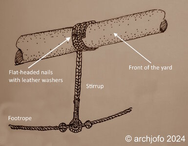
Based on Eberhard @welfalck's advice and further consideration, this seems to be the better and probably correct solution for attaching the stirrups.
The reverse arrangement ensures better drainage of rainwater. I have now also found an illustration of this in “Rundhölzer, Tauwerk und Segel” by K. Schrage.
Fußpferde_Bramrahen_V1_LaCreole.jpg
 
@Steef66

Hello dear Stephan,

I'm sorry, but I don't want to lecture here, I just want to provide information.
It is a well-established tradition that the stirrups were nailed down, at least in the 18th century to the beginning of the 19th century, as far as I know. You can read about this, for example in "Manuel de Greement" by F. A. Coste, edition 1829, in "The model of the brig Irene" by E. W. Petrejus, in "Mastning and rigging of ships of the 18th century" by K. H. Marquardt, "Rundhölzer, Tauwerk und Segel" by Klaus Schrage and certainly also in English specialist literature. Of course the French source is important for my model.
My question was what exactly the nailing looks like. There may also have been more nails, which would probably be difficult to show on the model at this scale. But I didn't find anything about it. So I made my suggestion as presented.
Always good to learn somethi g, this was something I didn't know, thanks for the lessen and where to find. I should buy the book of Marquardt. 18th and 19th century is for me still a part to learn more about. I wish I could help you with these nails.
 
Always good to learn somethi g, this was something I didn't know, thanks for the lessen and where to find. I should buy the book of Marquardt. 18th and 19th century is for me still a part to learn more about. I wish I could help you with these nails.
Do you know the web-page summarizing the work of K.H. Marquardt?
 
Hello Stephan,

Thank you for remembering my birthday.I am currently pursuing my old profession as an architect. My son and his girlfriend want to build a house soon. So dad has to do the draft planning, which is now available. I am currently preparing the service descriptions for the construction companies.But I already have withdrawal symptoms from model building. I'm already very hot, things will continue soon.
 
Continuation: Equipment of the fore topgallant yard – Vergue de petit perroquet
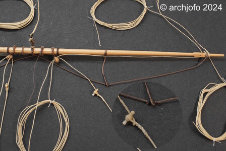
As announced a long time ago, I started to equip the fore topgallant yard. In principle it is the same rigging elements and accessories as the main topgallant yard, just with reduced dimensions.
In this respect, I don't want to repeat myself and let the pictures speak for themselves.
DSC01842.jpg

DSC01850.jpg

DSC01851.jpg

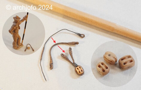
The double blocks for the royal sheets and the single cluelines are also a little smaller.
Here is a direct comparison of a quarter block for the main top gallant yard with those of the fore top gallant yard. Unfortunately, at this size you can already see some irregularities.


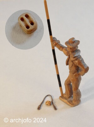
In the next photo I show, among other things: an already made strop for a double block with my scale man, which I've been neglecting a bit lately. Actually a loyal companion at the model building yard for more than 10 years now.
DSC01858.jpg

DSC01859.jpg

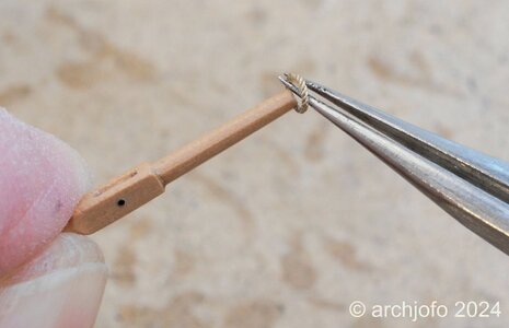
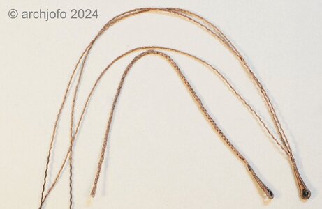
And here's another picture of the stirrups. On the one hand you can see the unraveled rope and on the other hand the finished braided plating.
DSC01860.jpg

The sheets are connected to the cluelines in the usual way when no sails were attached.
DSC01864.jpg

Finally, here is a picture of the entire fore topgallant yard, but still without lifts.
DSC01868.jpg

Sequel follows …
 
Back
Top