-

Win a Free Custom Engraved Brass Coin!!!
As a way to introduce our brass coins to the community, we will raffle off a free coin during the month of August. Follow link ABOVE for instructions for entering.
-

PRE-ORDER SHIPS IN SCALE TODAY!
The beloved Ships in Scale Magazine is back and charting a new course for 2026!
Discover new skills, new techniques, and new inspirations in every issue.
NOTE THAT OUR FIRST ISSUE WILL BE JAN/FEB 2026
You are using an out of date browser. It may not display this or other websites correctly.
You should upgrade or use an alternative browser.
You should upgrade or use an alternative browser.
La Créole 1827 by archjofo - Scale 1/48 - French corvette
Great work - when ever you need some additional income, you could easily start a new business .......@Uwek
Hello Uwe,
what do you think?
Of course I didn't buy the hooks.
I made master models for the hooks out of brass and then had them cast in a jewelry foundry using the lost wax process.
You metal work is from the same outstanding level as you rope work, Johann. A pleasure for the eyes!@pianoforte
@Mirek
@Uwek
Thank you very much for your interest and the nice comments.
Also many thanks to all for the LIKES.
Continuation: Peak halyard - Drisse de pic
The peak halyard of the French corvette led over a double block with iron fittings and was probably hooked to an eyebolt on the cap des mizzen mast, similar to a depiction in the Atlas du Génie Maritime.
View attachment 459007
Source: Atlas du Génie Maritime - detail
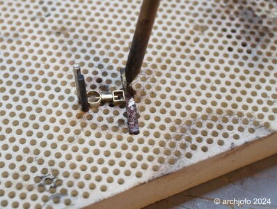
I made the double block with a length of approx. 4 mm in the usual method from service tree. The fittings were made in the manner already described from partially prefabricated etched and cast brass parts. The hard soldering of the hook is a tricky job, but I've managed it in the meantime with some practice. The biggest problem is destroying the part with too much heat from the torch.
View attachment 459002
After adjusting the fitting to the block and soldering in the hook, the solder joint was sanded clean.
View attachment 459003
The next two pictures show the finished double block with the eyebolt, which will later be attached to the cap.
View attachment 459004
View attachment 459005
And last but not least, a picture of the hooked double block.
View attachment 459006
Now there are still a number of different blocks to be made for the gaff and the boom.
To be continued ...
Regards, Peter
- Joined
- Nov 10, 2019
- Messages
- 479
- Points
- 373

Hello,
after a break I would like to continue with my construction report.
First of all, I would like to thank you for your interest and for sharing information. This way we all learn something new and develop our model building skills. Thank you very much!
Continuation: Equipment for the gaff and boom - boom sheets / Écoute de gui
etc.
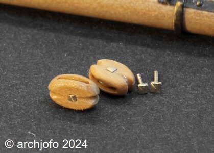
In the meantime I was able to make the blocks required for the gaff and boom. The single blocks for the mainsheets were given brass discs. For the block axles with the square heads I made two smaller versions, the smallest of which was used because of the better scale, as can be seen in the following picture.
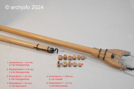
The next picture shows a compilation of the blocks that are attached to the gaff and boom using strops.
For the design of the mainsheet of the La Créole I based myself on the Paris model. There is one special feature to be mentioned in this context.
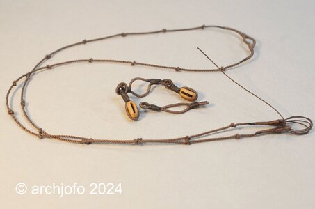
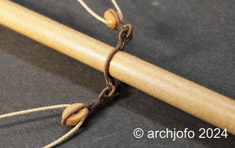
The Paris model of the La Créole is not a mainsheet as one usually knows it. In principle, this mainsheet of the French corvette consists of two tackles, the standing parts of which are attached to the end of the boom and thus also contribute to stabilizing the boom in the form of boom strops (see photo).
Apart from this model, I have never seen or heard of such a mainsheet, neither on contemporary models nor in the relevant specialist literature.
To be sure that this form actually existed, I tried to find it in the contemporary specialist literature in the book "Manuel de gréement" by F. A. Coste, Paris 1829. And in fact, on page 147, in addition to the usual versions, exactly this special type is described.
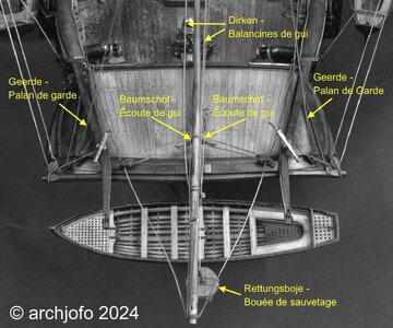
Source: Musée national de la Marine de Paris - La Créole
The following rigging elements were then required, manufactured and attached to the boom:
The next picture shows the partially rope stropped brail blocks, each double, for the gaff:
Below is a picture of the rigging elements that have now been mounted on the gaff:
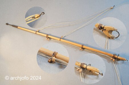
The vangs are still missing, which will then be attached to the model when the gaff is assembled. As far as I know, these are placed around the gaff with a clove hitch.
So now all the yards and spars of my corvette are equipped and ready for the final rigging.
To be continued...
after a break I would like to continue with my construction report.
First of all, I would like to thank you for your interest and for sharing information. This way we all learn something new and develop our model building skills. Thank you very much!
Continuation: Equipment for the gaff and boom - boom sheets / Écoute de gui
etc.
In the meantime I was able to make the blocks required for the gaff and boom. The single blocks for the mainsheets were given brass discs. For the block axles with the square heads I made two smaller versions, the smallest of which was used because of the better scale, as can be seen in the following picture.

The next picture shows a compilation of the blocks that are attached to the gaff and boom using strops.

For the design of the mainsheet of the La Créole I based myself on the Paris model. There is one special feature to be mentioned in this context.
The Paris model of the La Créole is not a mainsheet as one usually knows it. In principle, this mainsheet of the French corvette consists of two tackles, the standing parts of which are attached to the end of the boom and thus also contribute to stabilizing the boom in the form of boom strops (see photo).
Apart from this model, I have never seen or heard of such a mainsheet, neither on contemporary models nor in the relevant specialist literature.
To be sure that this form actually existed, I tried to find it in the contemporary specialist literature in the book "Manuel de gréement" by F. A. Coste, Paris 1829. And in fact, on page 147, in addition to the usual versions, exactly this special type is described.

Source: Musée national de la Marine de Paris - La Créole
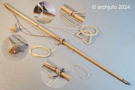
The following rigging elements were then required, manufactured and attached to the boom:


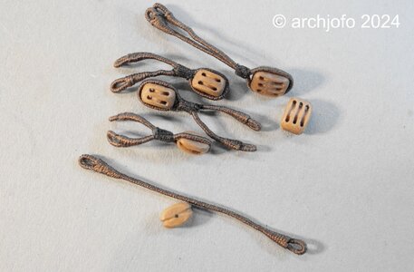
The next picture shows the partially rope stropped brail blocks, each double, for the gaff:

Below is a picture of the rigging elements that have now been mounted on the gaff:

The vangs are still missing, which will then be attached to the model when the gaff is assembled. As far as I know, these are placed around the gaff with a clove hitch.
So now all the yards and spars of my corvette are equipped and ready for the final rigging.
To be continued...
Amazing and absolutely fantastic as always, supernatural art.
einfach TOLL
Una delicia para la vista. Gracias por compartirlo.
Saludos
A delight to the eye. thanks for sharing it.
Cheers
Saludos
A delight to the eye. thanks for sharing it.
Cheers
Last edited:
Unparalleled excellence. Each post is a treasure. Just when I begin to think I might be getting the hang of this modelling thing I am (happily) reminded that there is still more to accomplish. Great stuff, Johann!
Hello Johann, wonderful update, absolutely fascinating. I went through your report again in the AK and noticed that you are using the ball matting from Clou. One question about that, do you mix it with the thinner from Clou as it says on the instructions? I have now tested a few surface treatments and nothing is as nice as it looks on your model. Too oily, too thick, too shiny, etc.
- Joined
- Nov 10, 2019
- Messages
- 479
- Points
- 373

Hello Tobias,
I'm glad you like it.
I use the bale matting from Clou undiluted. After applying it, I always sand the surface with extremely fine steel wool so that it doesn't shine. I repeat this process more often, depending on the component.
I know that the majority of model builders prefer oil. But I also go my own way with the material for the rigging...
Johann, thank you for your answer, I almost thought so. I used it undiluted on the inside of Le Rochefort and the result was not satisfactory, I also treated it with steel wool. The result is better than with the sanding primer from Clou but it doesn't look as good as it does on your model. I ordered the thinner on Saturday because there is no hardware store nearby and I hope it will arrive before the holidays. I also tried oil and it looks very good, but the dust sticks to it and that is really annoying.Hello Tobias,
I'm glad you like it.
I use the bale matting from Clou undiluted. After applying it, I always sand the surface with extremely fine steel wool so that it doesn't shine. I repeat this process more often, depending on the component.
I know that the majority of model builders prefer oil. But I also go my own way with the material for the rigging...
This is not the Proxxon MF70, but a normal drill stand from Proxxon MB 140/S MICROMOT, so nothing special.
View attachment 466254
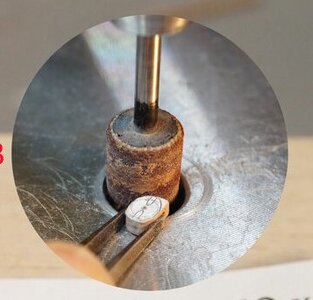
Wow, Johann, you opened up my eyes. I had never known the purpose of this hole in my Proxxon drill press!
That aside I just discovered this construction report. I spend whole day reading it. Still have a half of it to go. I am amazed. The work you do is incredible. I am learning some new for me and valuable techniques on every page of this report.
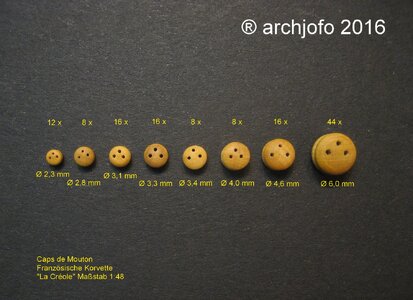
Is it possible you would show the process of how you make the deadeyes? I am especially interested in small ones. As small as 3 mm DIA or less. I need to make about 100 pieces for my model of this size and am on the crossroad for selection of technique I can use.
- Joined
- Nov 10, 2019
- Messages
- 479
- Points
- 373

Hello,
first of all, thank you for your interest in my construction report, which of course makes me very happy.
I am happy to comply with your request to show how I made the deadeyes.
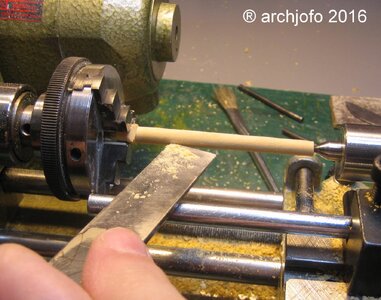
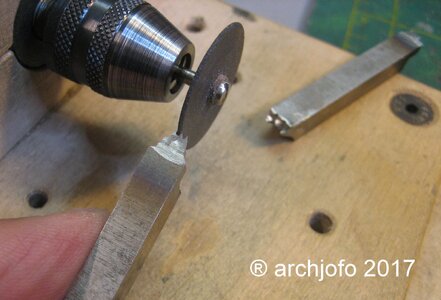
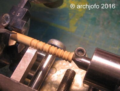
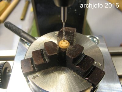
They are made of boxwood. I turned the round pieces of wood to the required diameters on my Unimat SL small lathe.
The rest of the manufacturing process is better explained by the following pictures:
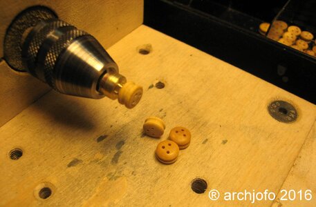
Here you can see how I sand the surface of the deadeyes cleanly. I made special holders for this purpose.
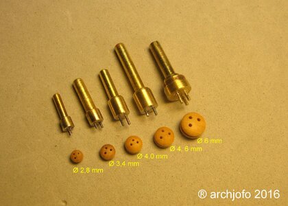
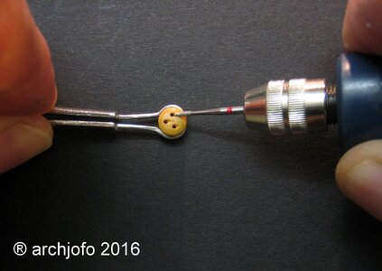
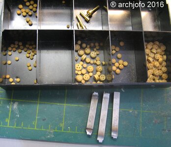
I hope that this has made my method for making the deadeyes, especially smaller diameters, clear to you.
I am of course happy to answer any further questions you may have.
first of all, thank you for your interest in my construction report, which of course makes me very happy.
I am happy to comply with your request to show how I made the deadeyes.
They are made of boxwood. I turned the round pieces of wood to the required diameters on my Unimat SL small lathe.
The rest of the manufacturing process is better explained by the following pictures:


Here you can see how I sand the surface of the deadeyes cleanly. I made special holders for this purpose.


I hope that this has made my method for making the deadeyes, especially smaller diameters, clear to you.
I am of course happy to answer any further questions you may have.
Hi,Johann. Thank you very much for perfect explanation of the deadeye manufacturing.
Actually I do have another question. When I was doing silver soldering I always had serious problems with securings the soldered parts to the ceramic plate. I noticed you had some holders designed for this purpose. Could you please show how you managed to mount them onto the small holes in the ceramic plate? Also how are these holders made adjustable? Thank you very much in advance.
Actually I do have another question. When I was doing silver soldering I always had serious problems with securings the soldered parts to the ceramic plate. I noticed you had some holders designed for this purpose. Could you please show how you managed to mount them onto the small holes in the ceramic plate? Also how are these holders made adjustable? Thank you very much in advance.
Hi, Johann. Many thanks for the link to the soldering plate holder. I will be trying to source these on Amazon Canada. They will be invaluable for doing soldering work.
One more question about the cutters you made for deadeyes. By the picture it seems the ends of cutters underwent some heat treatment. I would imagine the cutters were the high speed steel bars. Did you anneal them before shaping the cutters? Did you hardened them back? Could you please describe the process of how you heat treated them?
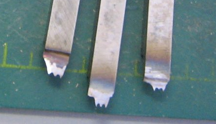
One more question about the cutters you made for deadeyes. By the picture it seems the ends of cutters underwent some heat treatment. I would imagine the cutters were the high speed steel bars. Did you anneal them before shaping the cutters? Did you hardened them back? Could you please describe the process of how you heat treated them?

Kurt Konrath
Kurt Konrath
I have a question about the item on left, that looks like a bobbin with post and ropes, what was purpose of this item? Looks like a floating bobber to assist someone in the water? Or an anchor Bouey?
- Joined
- Aug 8, 2019
- Messages
- 5,584
- Points
- 738

I have a question about the item on left, that looks like a bobbin with post and ropes, what was purpose of this item? Looks like a floating bobber to assist someone in the water? Or an anchor Bouey?
3 pictures above it there is the name Rettungsboje = Lifebuoy


