La Créole 1827 by archjofo - Scale 1/48 - French corvette

At MSW, a fellow model maker expressed the wish to see the entire model in its current condition.
I borrowed the black blanket from my wife for a moment and tried to take a few useful pictures.
Of course, the model looks a little messy in this condition.
Also, I'm not a professional when it comes to photography. But soon I will get myself a real background for taking pictures so that I can bring the whole model onto the picture.

_DSC7691_wett.jpg

_DSC7692_wett.jpg

_DSC7693_wett.jpg

_DSC7690_wett.jpg
 
Last edited:
Hello,
I am very happy about the nice comments from all of you and the many LIKES.

Continuation: Mizzen topgallant stay - Étai mât de perruche de perroquet
As already reported on this topic some time ago (LINK), the monograph by J. Boudriot does not reveal in detail how the mizzen topgallant stay was attached. In this respect, I orientated myself on examples from relevant literature.
Before attaching the stay (model rope ø 0.46 mm), its length must be determined on the model, as it is guided over a single block (length 4 mm) and integrating the thimble on the model is not necessarily recommended.
DSC00220.jpg

The next picture shows the finished mizzen topgallant stay and the two-legged sling (counterpart for the lanyard lashing), which is attached to the trestle trees.
DSC00221.jpg

The lanyard for the lashing to fix the mizzen topgallant stay was set up with a simplified splice or fake splice (unfortunately I don't know the English name).
DSC00225.jpg

DSC00231.jpg

In the last picture you can see the finished lanyard lashing. A corresponding enlargement in the cut-out at the top left.
DSC00236.jpg

Sequel follows …
 
@Gennaro
@pianoforte
Thank you very much for the approval,
and all ohters für the LIKES.
With unwavering perseverance and joy, here we go:

Continuation: Main topgallant stay - Étai grand mât de perroquet
Analogous to the mizzen topgallant stay, the main topgallant stay (ø 0.58 mm in 1:48 scale) is made and fixed, but it is not guided to the main top by a single block, but by a guide collar with integrated thimble.
The guide collar, consisting of a leg strop (ø 0.35 mm in model scale 1:48) with eye splices at the ends, was completely served. The following picture shows the serving machine with the finished stropp, into which the thimble was subsequently bound.
DSC00239.thumb.jpg.d83539a56c033a014aac05d9cac50d56.jpg

The next picture shows the finished arrangement of the main topgallant stay.
DSC00240.thumb.jpg.8e0f9b70c32cf3f3a7be3be3ee452efa.jpg

The leading collar is attached with a lashing around the main topgallant mast.
Before I could attach the main topgallant stay to the model, however, a small area had to be served where the lead-through is through the thimble of the guide collar. The main topgallant stay did not need this serving, because it was led through a block disk and therefore there was less danger of falling into the pubic.
Bramstengestag.thumb.jpg.092d7333281f1b534a3633011681286e.jpg
Source: Atlas du Génie Maritime, Annexe Pl. 1

Finally, the lashing was made and the main topgallant stay was fixed to the two-legged strop in the top.
DSC00243.thumb.jpg.b97fc8d86c7445ffb17eb23811f8e33f.jpg

DSC00245.thumb.jpg.d5caa8c9e8792899f43c11dded175687.jpg

DSC00257.thumb.jpg.b6a4f5a69acdb78383c555a421876aad.jpg

See you soon ...
 
Hello,
thank you all for your positive comments and thanks for the LIKES.

Continuation: Rigging work - height-adjustable work platform
Today I would like to say a few words about the design of the working platform as part of the further rigging work for my French corvette.
Who doesn't try to design the working environment in such a way that one can work effectively and especially ergonomically advantageous. I have therefore followed with great interest the discussions that have taken place from time to time on this subject in various forums.
Especially when working on the rigging of a 1:48 scale model, one feels the need to adjust the height of the working area continuously, depending on the area of the rigging in which one is working. Adjusting the seat height or working on the model standing up has its limits. It is of course more obvious to raise or lower the model (actually even more important).
As I plan to complete the difficult weaving of the shrouds in the near future, and also with a view to the further rigging work on the current property, I thought about how I could realise a stepless height adjustment of the model for my needs.
Inspired by the restoration workshop of the Musée national de la Marine in Paris, where scissor lift tables are used as working platforms for the ship models, I searched the net specifically for a similar solution. The work platforms used by the Paris museum cost up to several thousand euros, which of course was out of the question for me.
Muse_de_la_Marine_Arbeitsplattform.JPG
Source: Musée national de la Marine in Paris

After some time I found what I was looking for and bought a mini scissor lift table for relatively little money, as can be seen in the following pictures:
_DSC7762_forum.jpg

_DSC7759_forum.jpg


The minimum height is about 35 cm, and the working platform can be raised or lowered continuously by foot pedal to about 87 cm with a small hydraulic cylinder. This height difference is more than sufficient for my purposes, as is the load capacity with 150 kg.

See you soon ...
 
Last edited:
Hello,
thank you all for your positive comments and thanks for the LIKES.

Continuation: Rigging work - height-adjustable work platform
Today I would like to say a few words about the design of the working platform as part of the further rigging work for my French corvette.
Who doesn't try to design the working environment in such a way that one can work effectively and especially ergonomically advantageous. I have therefore followed with great interest the discussions that have taken place from time to time on this subject in various forums.
Especially when working on the rigging of a 1:48 scale model, one feels the need to adjust the height of the working area continuously, depending on the area of the rigging in which one is working. Adjusting the seat height or working on the model standing up has its limits. It is of course more obvious to raise or lower the model (actually even more important).
As I plan to complete the difficult weaving of the shrouds in the near future, and also with a view to the further rigging work on the current property, I thought about how I could realise a stepless height adjustment of the model for my needs.
Inspired by the restoration workshop of the Musée national de la Marine in Paris, where scissor lift tables are used as working platforms for the ship models, I searched the net specifically for a similar solution. The work platforms used by the Paris museum cost up to several thousand euros, which of course was out of the question for me.
View attachment 265419
Source: Musée national de la Marine in Paris

After some time I found what I was looking for and bought a mini scissor lift table for relatively little money, as can be seen in the following pictures:
View attachment 265417

View attachment 265418

The minimum height is about 35 cm, and the working platform can be raised or lowered continuously by foot pedal to about 87 cm with a small hydraulic cylinder. This height difference is more than sufficient for my purposes, as is the load capacity with 150 kg.

See you soon ...
Clever! I gotta find table like this - back is killing me with the current build, working standing most of the time.
 
Garnet tackle - Palan d'etai
The garnet tackle were generally used for loading goods, cannons and for lowering and hoisting boats.
With regard to the execution of the stage tack, there are differences between the graphic representation of J. Boudriot in the monograph and the original model in the Paris Museum compared to the model of La Créole.

LaCreole_Monographie_S125.jpg
Source: Monograph La Creole by J. Boudriot pp. 125 and 126

Palans_de_etai_LaCreole_2.thumb.jpg.b0341743829c4f64186f4cfcd0ed1a2b.jpg
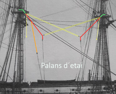
Source: Monograph La Creole by J. Boudriot p. 101, photo detail of the original model

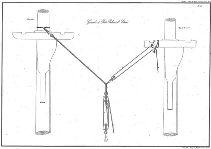
The execution of the garnet tackle documented in the Atlas du Génie maritime corresponds to the representation on the Paris model. Accordingly, I also do this on my La Créole model.
palans_de_etai_Altlas.thumb.jpg.e96d25d48594e246a72fc897e99ca174.jpg
Source: Atlas du Génie maritime, annexe no.1, pl. 50

I was able to identify another garnet tackle on the photo of the original model. I will also represent this accordingly on my model.
I started the preparations for the appropriate arrangements of these rigging details with the production of the double and single blocks. A total of 6 double and 4 single blocks are to be produced. I determined the block size by scaling the drawings from the atlas in comparison with the block list from the monograph (dependency on the rope diameter), which ultimately fitted pretty well. Thus, the double blocks have a length of around 6.8 mm and the single blocks have a length of around 5.2 mm. The blocks were made in the manner that has meanwhile been tried and tested for me.
In this context I would like to emphasize that, from my point of view, it makes no sense to prepare the blocks in their entirety in advance. That would be several hundred blocks for this corvette. In the meantime I have laboriously learned that all these blocks have the most varied of sizes and shapes, depending on the purpose. There are also many differences in terms of their fittings and fastening. That's why I manufacture the blocks individually based on the respective detail section. Due to the complexity of rigging, any other approach does not seem expedient to me, unless one simplifies and differentiates less, which of course is at the expense of the level of detail. Ultimately, everyone has to decide for themselves.
DSC00268.jpg

DSC00270.jpg


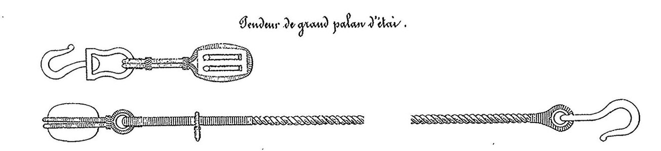
As can be seen on the following drawing from the Atlas du Génie maritime, the French used heavy garnet tackle blocks with so-called swivel hooks (croc à émerillon).

Palans_de_etai_LaCreole_Atlas_Talje.thumb.jpg.2f1eb119b5495a6b8260d93e3cd661a5.jpg
Source: Atlas du Génie maritime, annexe no.1, pl. 2

Below is a picture collage for making the swivel hooks.
DSC00276.JPG


The majority of the required blocks, thimbles and hooks for the arrangements of the garnet tackle were made as far as can be seen in the next picture.
DSC00278.jpg

The manufactured brass parts are of course burnished to give them an iron-like appearance.
The next step is to make the garnet tackle. For this I still have to make the ropes in the appropriate strengths and serve. The necessary block strops must also be made.

Sequel follows …
 

Attachments

  • palans_de_etai_Altlas.jpg
    palans_de_etai_Altlas.jpg
    105.2 KB · Views: 13
  • Palans_de_etai_LaCreole_2.jpg
    Palans_de_etai_LaCreole_2.jpg
    500.3 KB · Views: 11
  • Palans_de_etai_LaCreole_Atlas_Talje.jpg
    Palans_de_etai_LaCreole_Atlas_Talje.jpg
    47.6 KB · Views: 10
Last edited:
Everything about this model looks right. Great work!
What type of wood are you using. There is a lack of noticeable grain which helps with scale appearance.
 
Hallo Johann,
I really would like to see your model once in real - I have to see these superb details somehow "face to face"
Is there a possibility, that you maybe also come next March to Augsburg?
 
Back
Top