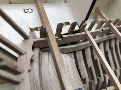
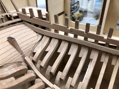
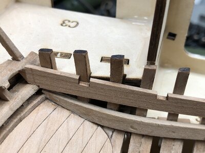
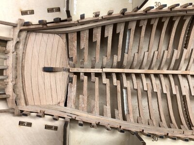
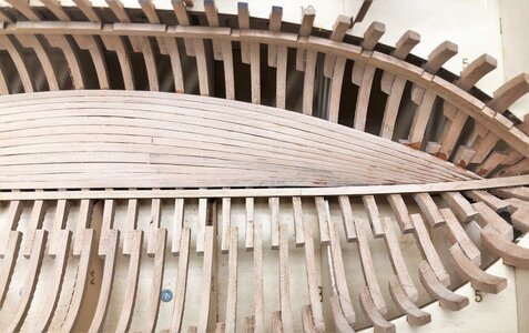
LE COUREUR - french Lugger 1776 - POF kit from CAF in 1:48 by Uwe

Well done Uwek. I'll follow your example in the next days
Thanks - so I am looking forward to see yours.

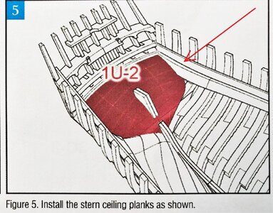
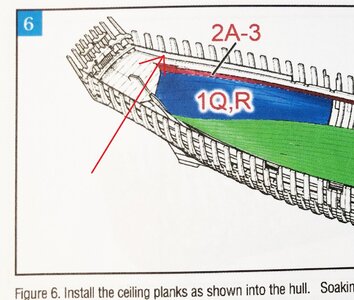
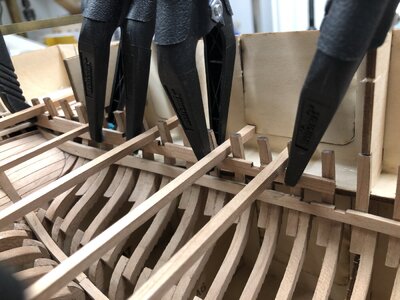
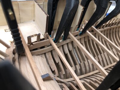
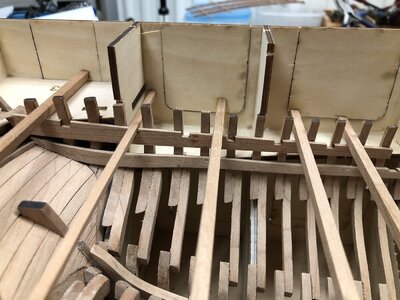
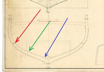
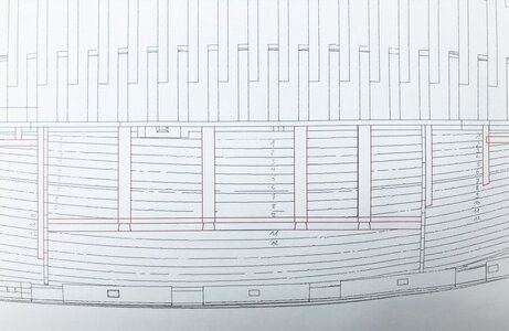
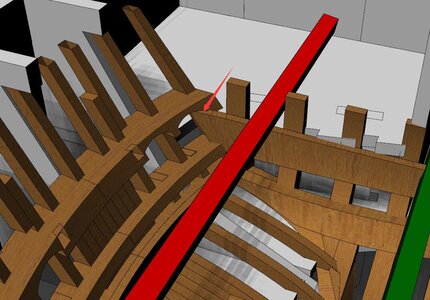
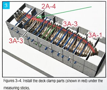
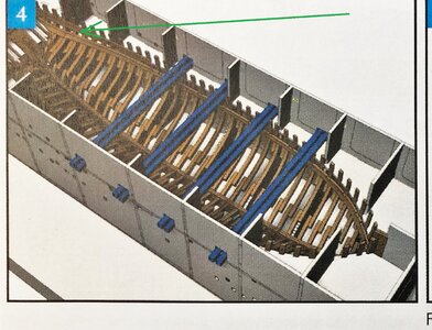
Next clamp to be installed was the Part 2A-4- marked with the green arrow in the following sketches of the manual
IMG-4871aa.jpg IMG-4872aa.jpg

Be aware, that on these sketches a different plank is shown and not the Part 2A-4, therefore it is marked with a red arrow - I mention this in order not to get confused
IMG-4872aaa.jpg IMG-4873aa.jpg

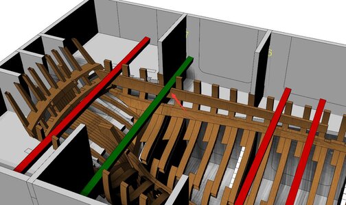
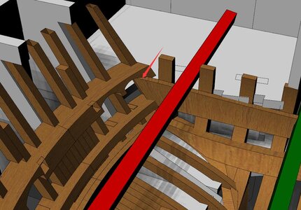
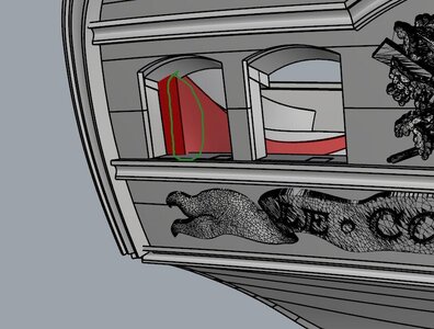
CAF already clarified this and was posting already a correct detail, to show the correct location of this part
174.jpg

176.jpg

175.jpg

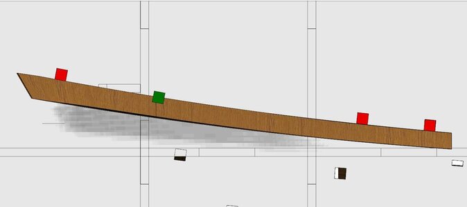
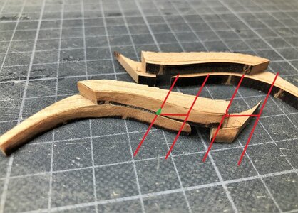
For the correct level the three red and one green measuring stick should be used.
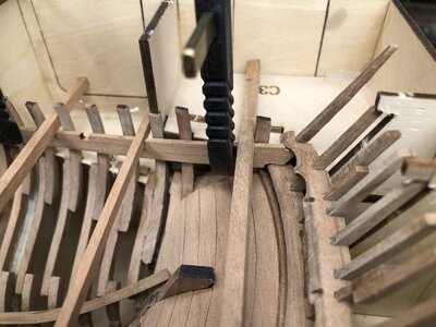
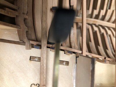
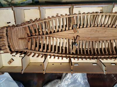
In the following photos you see the dry fitted part, because the end of the clamp has to be adjusted and sanded to the correct form, so that it fits into the stern structure
IMG-4896.jpg

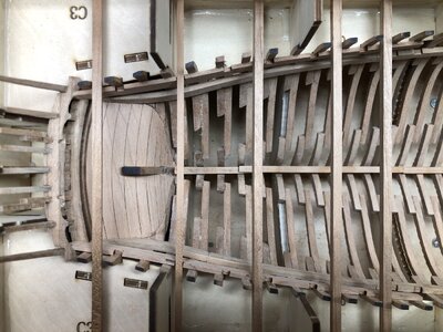
the same situation from the top
IMG-4897.jpg

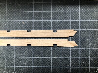
Here you can see the necessary sanding and adjustments so it fits - I think everybody else´s part could look different, but I guess that everybody has to sand something
IMG-4901.jpg

Fixing procedure - before I put the part for some time in water
IMG-4902.JPG

you can see also the use of the measuring sticks in order to get the correct vertical and horizontal location
IMG-4903.jpg

The glue is fixed, the clips are removed
IMG-4904.jpg

IMG-4905.jpg

IMG-4906.jpg

and the final result
IMG-4907.jpg

IMG-4908.jpg

IMG-4909.jpg

IMG-4911.jpg

Many Thanks for your interest - wish you all good luck with the clamps Thumbs-Up
 
Thanks - so I am looking forward to see yours.

Next clamp to be installed was the Part 2A-4- marked with the green arrow in the following sketches of the manual
View attachment 192111 View attachment 192112

Be aware, that on these sketches a different plank is shown and not the Part 2A-4, therefore it is marked with a red arrow - I mention this in order not to get confused
View attachment 192113 View attachment 192114

CAF already clarified this and was posting already a correct detail, to show the correct location of this part
View attachment 192108

View attachment 192110

View attachment 192109

For the correct level the three red and one green measuring stick should be used.
In the following photos you see the dry fitted part, because the end of the clamp has to be adjusted and sanded to the correct form, so that it fits into the stern structure
View attachment 192115

the same situation from the top
View attachment 192116

Here you can see the necessary sanding and adjustments so it fits - I think everybody else´s part could look different, but I guess that everybody has to sand something
View attachment 192098

Fixing procedure - before I put the part for some time in water
View attachment 192099

you can see also the use of the measuring sticks in order to get the correct vertical and horizontal location
View attachment 192100

The glue is fixed, the clips are removed
View attachment 192101

View attachment 192102

View attachment 192103

and the final result
View attachment 192104

View attachment 192105

View attachment 192106

View attachment 192107

Many Thanks for your interest - wish you all good luck with the clamps Thumbs-Up
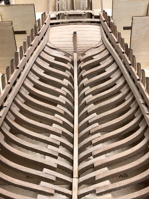
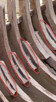
Excellent job on a very difficult piece. Interesting how clamps bow at the aft side. Frames look extremely fragile, only a small overlap that holds them together. What's the frame thickness? Thanks for sharing.
 
Excellent job on a very difficult piece. Interesting how clamps bow at the aft side. Frames look extremely fragile, only a small overlap that holds them together. What's the frame thickness? Thanks for sharing.
Hallo and many thanks for your interest.
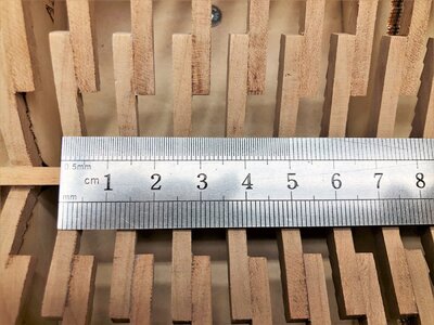
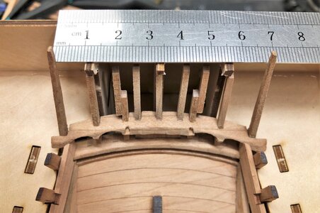
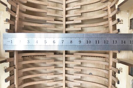
To answer your question, I made some photos with a ruler (in centimeter), so you can get a good feeling for the parts and the fragility. The high quality of the timber is helping, that not so much parts are breaking.......

IMG-4925.jpg

IMG-4926.jpg

IMG-4927.jpg
 
May I ask you Uwe, how do you get all the frames so clean?
On many of my frames there is some laser char left around the areas where the frame is double. I'm at work so I do not have a good picture but just to explain what I mean:
1605174779025.png
I guess it must be due to insufficient accuracy from my side when gluing the parts together. But if that is the case then it is - just as when making the sexy woman from the accounting dept. pregnant at the Christmas party - impossible to unscrew :oops:.
Inside the hull I think most of it can be fixed by slightly over fairing but I'm concerned about spots on the outside of the hull where it is to be left without planking
 
May I ask you Uwe, how do you get all the frames so clean?
On many of my frames there is some laser char left around the areas where the frame is double. I'm at work so I do not have a good picture but just to explain what I mean:
View attachment 192302
I guess it must be due to insufficient accuracy from my side when gluing the parts together. But if that is the case then it is - just as when making the sexy woman from the accounting dept. pregnant at the Christmas party - impossible to unscrew :oops:.
Inside the hull I think most of it can be fixed by slightly over fairing but I'm concerned about spots on the outside of the hull where it is to be left without planking
Hallo Poul,
I am using a sharp small chisel to remove the last areas of char you are showing in your photo.
With this I produce a small step, but this small step is much less visible, than the rest of the char
somehow like this shown with the lines
IMG-4559.jpg
 
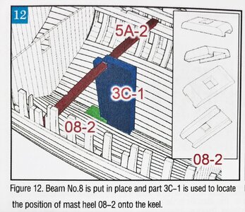
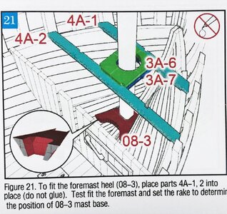
In post #149 of this topic I showed the two mast feet


I wrote:
and during waiting the glue drying I filed the two mast feet / mast heels into form

IMG-4853.jpg


IMG-4858.jpg

I followed the fairing lines on the part, without checking the manual


Important:
Be aware, that the left one Part 08-2 was not correctly done, which I realized after reading and studying the manual of the second box -> take a look at this sketch from the manual
IMG-4912.jpg

You can see in detail on the right side, how it should look like - so later on I have to make this part from scratch

The other one, Part 08-3 seems to be correct
IMG-4913.jpg
 
Last edited:
Hi Uwek .
Very nice job, as usual.
The 08-2 and 08-3 are luckly the only part of "your instruction" that I have not followed until now! That said, I really don't think it's an impossible challenge for you to redo the piece with leftover material .
I' m more or the less close to end the keel klamp. Over the weekend I will also update my building log with some photos
 
The next step will be the inner planking of the hull. In this post (and I am still doing) you can find the results of the research

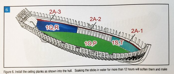
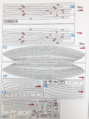
Let us take a look at the manual
IMG-4873.jpg
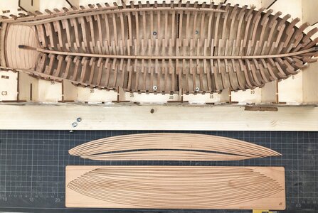
Means the first planks will be these close to the keelson - from sheets 1O and 1P

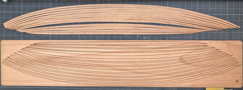
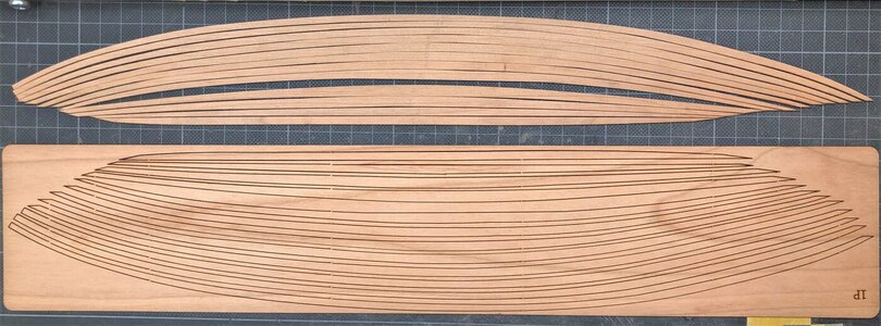
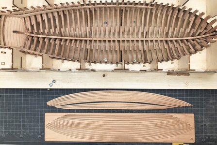
Here are the laser cut planks of 1O removed from the sheet and 1P still fixed
for each side of the hold we have 12 planks prepared
IMG-4919.jpg

IMG-4920.jpg

IMG-4921.jpg

IMG-4928.jpg
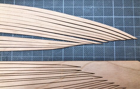
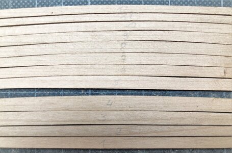
visible is that the form of plank 1 to 4 fits very good - the form of 4 to 5 are different - but once more 5 to 12 are very close - so it seems, that there is maybe once more an unplanked space between 4 and 5 planned (but not shonw in any drawing)


Now let us take a look at the test kit build of CAF, where I thought to find out, on which exact location fore and aft the first plank should be installed
1.jpg

10.jpg

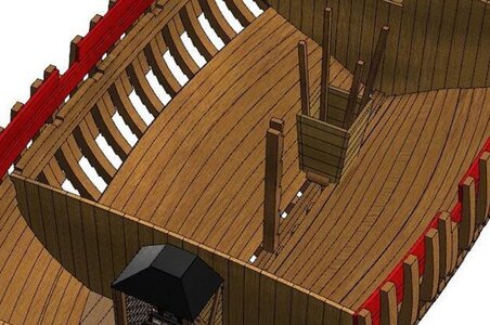
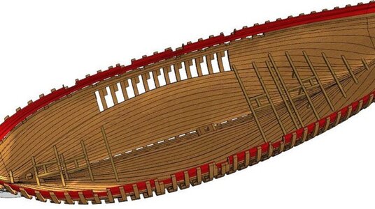
Here you can see the 3D-sketches from CAF, where you can see, that the first plank is not directly close to the keelson, but left a space for the limber board - also shown are 12 planks
3.jpg.10b5aa7bb3b96fefb2eb015de2f5e610a.jpg

45.jpg

Now let us take a look at the contemporary drawing of the Le Coureur, which is still available at the NMM
j0873aa.jpg

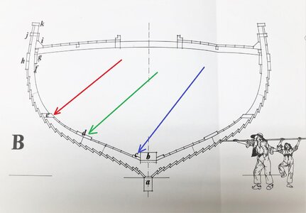
and with better quality the cross section available from Jean Boudriot drawing set / monograph of the Le Coureur
IMG-4923a.jpg

We can see some more details
first of all with "c" marked the limber board (blue arrow)
with "d" marked the "thick stuff" plank over the floor heads (green arrow)
and with "e" a special board which covers the space between the frames (red arrow)
- with this the inner planking is closed, so that no material can fall between the frames - in addition I am sure it would also stiffen the complete hull structure, especially because there is no second Thick stuff row of planks existing.

If we count the "d" board with 2 planks - Boudriot is also showing 12 planks (exclusive limber board)

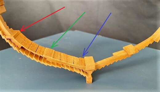
To show it here you can find a excerpt of a section model of the Le Coureur build by Giorgio Munisso from Uruguay (this section is standing close to his full hull model in order to explain the structure)
Cross section a.jpg

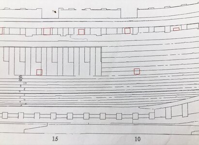
and now also the drawings of the kit from CAF - marked are here with the numbering (pencil) the 12 planks
IMG-4922.jpg

IMG-4924.jpg

Visible here are also the gap between the keelson and plank 1 - limber board - also visible here are the locations (approximately) where the first plank will start and has to end

My Resumee (in moment):
1) first plank has not to be close to the keelson, but with a space for the limber boards
2) maybe I change one plank from the kit a prepare a scratch one to imitate the Thick Stuff plank
3) maybe also the additional board beteeen the frames - but this I can decide still later (red arrows)
4) still open is the possible space between plank 4 and 5 - I will see when 1 to 4 are installed
But maybe Tom from @CAFmodel can highlight me here......
 
The next step will be the inner planking of the hull. In this post (and I am still doing) you can find the results of the research

Let us take a look at the manual
View attachment 192512
Means the first planks will be these close to the keelson - from sheets 1O and 1P

Here are the laser cut planks of 1O removed from the sheet and 1P still fixed
for each side of the hold we have 12 planks prepared
View attachment 192513

View attachment 192514

View attachment 192515

View attachment 192529
visible is that the form of plank 1 to 4 fits very good - the form of 4 to 5 are different - but once more 5 to 12 are very close - so it seems, that there is maybe once more an unplanked space between 4 and 5 planned (but not shonw in any drawing)


Now let us take a look at the test kit build of CAF, where I thought to find out, on which exact location fore and aft the first plank should be installed
View attachment 192516

View attachment 192517

Here you can see the 3D-sketches from CAF, where you can see, that the first plank is not directly close to the keelson, but left a space for the limber board - also shown are 12 planks
View attachment 192518

View attachment 192519

Now let us take a look at the contemporary drawing of the Le Coureur, which is still available at the NMM
View attachment 192521

and with better quality the cross section available from Jean Boudriot drawing set / monograph of the Le Coureur
View attachment 192520

We can see some more details
first of all with "c" marked the limber board (blue arrow)
with "d" marked the "thick stuff" plank over the floor heads (green arrow)
and with "e" a special board which covers the space between the frames (red arrow)
- with this the inner planking is closed, so that no material can fall between the frames - in addition I am sure it would also stiffen the complete hull structure, especially because there is no second Thick stuff row of planks existing.

If we count the "d" board with 2 planks - Boudriot is also showing 12 planks (exclusive limber board)

To show it here you can find a excerpt of a section model of the Le Coureur build by Giorgio Munisso from Uruguay (this section is standing close to his full hull model in order to explain the structure)
View attachment 192526

and now also the drawings of the kit from CAF - marked are here with the numbering (pencil) the 12 planks
View attachment 192527

View attachment 192528

Visible here are also the gap between the keelson and plank 1 - limber board - also visible here are the locations (approximately) where the first plank will start and has to end

My Resumee (in moment):
1) first plank has not to be close to the keelson, but with a space for the limber boards
2) maybe I change one plank from the kit a prepare a scratch one to imitate the Thick Stuff plank
3) maybe also the additional board beteeen the frames - but this I can decide still later (red arrows)
4) still open is the possible space between plank 4 and 5 - I will see when 1 to 4 are installed
But maybe Tom from @CAFmodel can highlight me here......
Hi Uwe, great to see you lead the way as there are definitely some anomalies and decisions to be made. I looked at the inner planking Q/R and 2A-3. Particularly fitting 2A-3 to the lower deck clamps seems to indicate a gap. Like you said, hopefully Tom @CAFmodel will give us some guidance.
 
Hallo and many thanks for your interest.
To answer your question, I made some photos with a ruler (in centimeter), so you can get a good feeling for the parts and the fragility. The high quality of the timber is helping, that not so much parts are breaking.......

View attachment 192282

View attachment 192283

View attachment 192284
Amazing. Only 4mm thick frames with overlap of about 1cm. Did you bolt futtocks together (I can't see them) or is it just glue that holds them together? Great job you're doing here Uwe. Thanks for sharing.
 
Amazing. Only 4mm thick frames with overlap of about 1cm. Did you bolt futtocks together (I can't see them) or is it just glue that holds them together? Great job you're doing here Uwe. Thanks for sharing.
Hallo my friend,
many thanks for your interest in this build and your kind words.
I did not use any bolts or nails to keep the parts together - pure wood glue -> it is working well when you not produce bigger forces towards the frames - by accident it can happen, that one frame is breaking, but than inside one part (floor timber, futtock, top timber) along the grain, so can be easily repaired
Looking at Tom’s built I can’t see the gap between the keelson and the inner hull planking.
8D340843-2F8D-4FD2-9264-8F33D86D3371.jpeg

maybe Tom @CAFmodel can help us out
 
Last edited by a moderator:
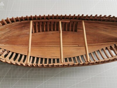
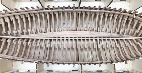
Now we come really to the inner planking, which I started during the last weekend

In the beginning I wanted shortly to show once more the the first planking strips of the sheets 1 O and 1 P.
IMG-4920.jpg

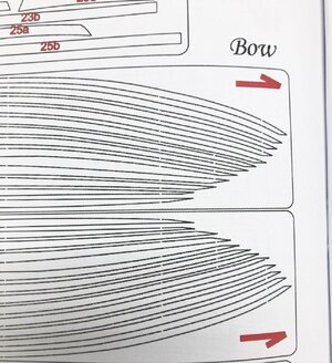
When you look at these strips it is maybe also not completely clear in which direction they have to be installed.
Here the manual is showing the direction with some small red arrows and the word "Bow"
-> so check this twice before you use the first glue
IMG-4930.jpg

IMG-4931.jpg

This means that the orientation should be like this:
IMG-4919.jpg
 
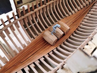
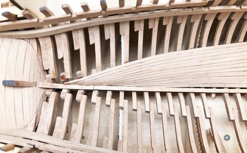
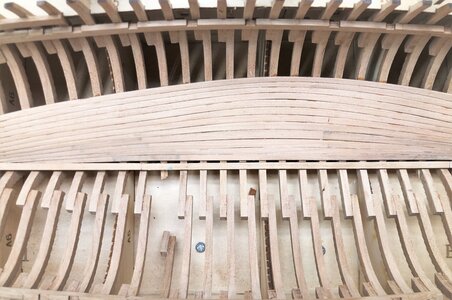
So I started with the inner planking works first with the first four rows.
And you see, that I left between the keel and the first plank a gap for the limber board

IMG-4929.jpg
You maybe recognize the dark stain on the planks - this was my fault, due to the fact, that I was butting a steel weight on top of the planks during watering - hope that I can remove it later on with sanding....
Where to start with the first plank I tried to follow this drawing from CAF
IMG_60431a.jpg
Here are the planks shown also with the limber board gap

and now the planking finished with sheet "1 O"
IMG-4933.jpg

IMG-4934.jpg

IMG-4935.jpg

Two hints, which are helping maybe also other modelers:

1) Put the strips for some time in water before you try to adjust and install them - this is making them much more flexibel and you can adjust them
2) It is every time not easy to fix inner planks correctly during the glue is drying - so I used wood glue on every 50% of the frames and 50% superglue, especially at the ends of the planking -> for me this way was working very good
 
Back
Top