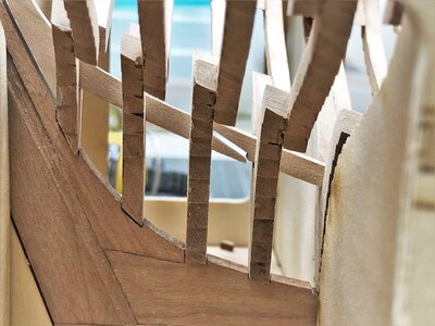
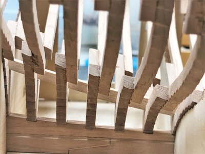
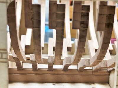
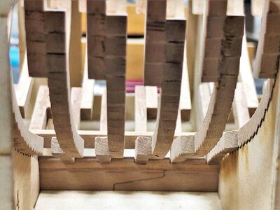
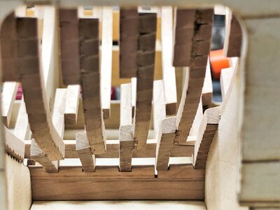
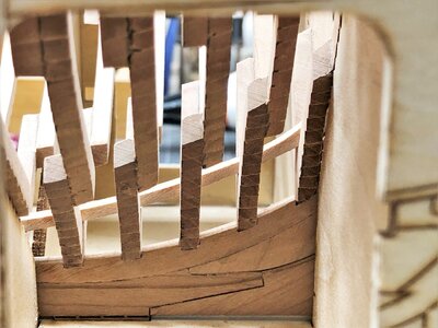
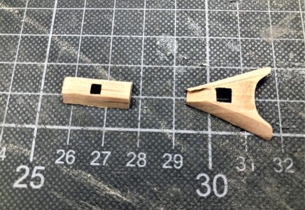
Uwe, watching your thoughtful an clean handwork is a real pleasure. Because of you one can bwtter understand the complicated structure of the stern.
-

Win a Free Custom Engraved Brass Coin!!!
As a way to introduce our brass coins to the community, we will raffle off a free coin during the month of August. Follow link ABOVE for instructions for entering.
-

PRE-ORDER SHIPS IN SCALE TODAY!
The beloved Ships in Scale Magazine is back and charting a new course for 2026!
Discover new skills, new techniques, and new inspirations in every issue.
NOTE THAT OUR FIRST ISSUE WILL BE JAN/FEB 2026
- Home
- Forums
- Ships of Scale Group Builds and Projects
- Le Coureur 1776 1:48 PoF Group Build
- Le Coureur 1776 1:48 Group Build Logs
You are using an out of date browser. It may not display this or other websites correctly.
You should upgrade or use an alternative browser.
You should upgrade or use an alternative browser.
LE COUREUR - french Lugger 1776 - POF kit from CAF in 1:48 by Uwe
Many thanks to all for your interest and your kind words and likes 


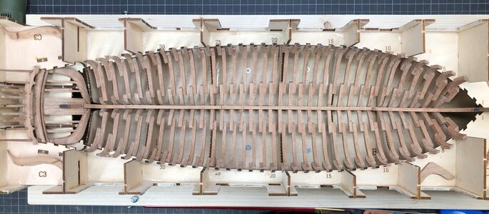
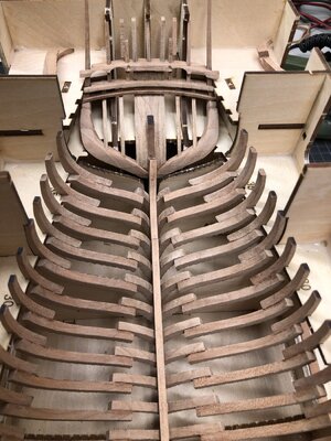
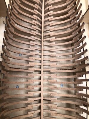
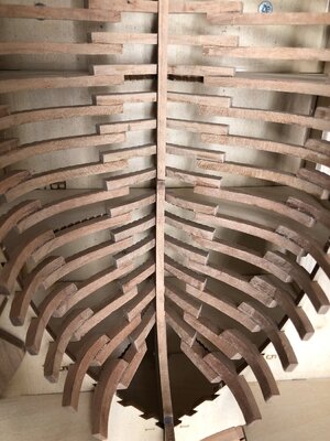
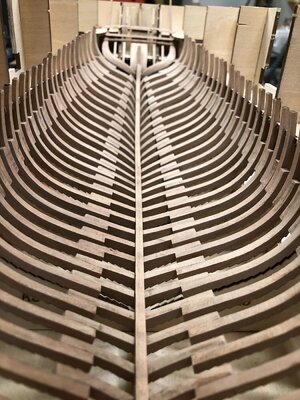
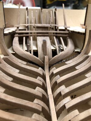
After finishing the stern structure I was able to come back to the "normal" frames and cleaned all of them mostly from the char. In addition I decided to bevel also completely the inside of the frames to the final forms. I realized, that the parts are so accurate prepared, that I left more or less no "meat"....... here the overview of the frames still dry on the keel.
Important: When you prepare the final touch of every single frame, do not forget to check already the fitting with the keelson, which will be installed afterwards, but it is much easier now with every single frame, than afterwards when they are all fixed to the keel.
Complete birds view


Kurt Konrath
Kurt Konrath
That is a lot of ribs for sure! If only they had a coating of meat and sauce!
Many Thanks for the comment - So hope to see an update on your log soonLooking good! About 20 frames behind you.
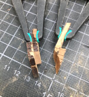
Frame on Axis 38 - unfortunately I did not find any real information of how it is looking like, there is no frame drawing existing, so I interpreted the 4 parts in this way
Front and back side visible
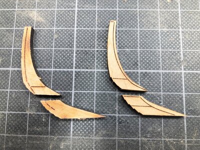
fixed together
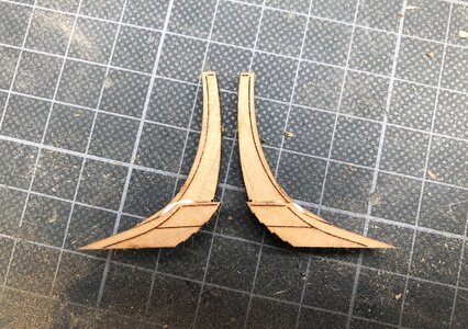
preliminary sanding on the frame on the left - on the right side the counterpart not prepared
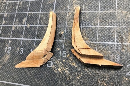
Until now I did not find a clear opinion and reason about and for the horizontal line
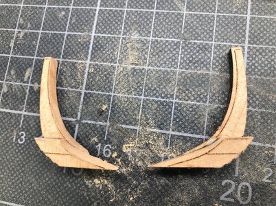
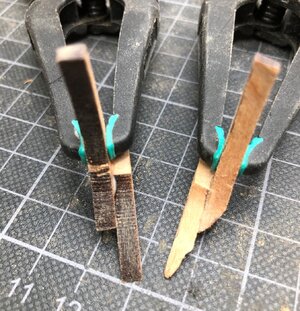
and dry-fitted on the counter timber of the stern structure
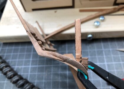
Visible now is once more the horizontal line - now I guess this base part of the frame has also to be faired
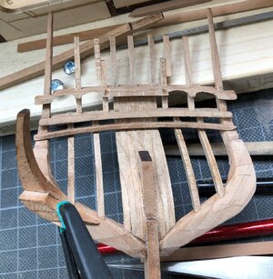
Front and back side visible

fixed together

preliminary sanding on the frame on the left - on the right side the counterpart not prepared

Until now I did not find a clear opinion and reason about and for the horizontal line


and dry-fitted on the counter timber of the stern structure

Visible now is once more the horizontal line - now I guess this base part of the frame has also to be faired

In other building log was a short talk about the fitting of frame 35 in the jig.
I had the same problem, and after checking the frame by itself, compared with the drawing, I was convinced, that I have to adjust slightly the jig, so that the frame can fit in. So I removed a little bit of the jig at frame 34 and 35 - this was my way .....
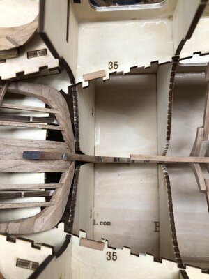
I had the same problem, and after checking the frame by itself, compared with the drawing, I was convinced, that I have to adjust slightly the jig, so that the frame can fit in. So I removed a little bit of the jig at frame 34 and 35 - this was my way .....

That is really clever. And it solves the issue of frame 35 determining the order of which the frames must be glued in.In other building log was a short talk about the fitting of frame 35 in the jig.
I had the same problem, and after checking the frame by itself, compared with the drawing, I was convinced, that I have to adjust slightly the jig, so that the frame can fit in. So I removed a little bit of the jig at frame 34 and 35 - this was my way .....
View attachment 189354
- Joined
- Mar 19, 2020
- Messages
- 206
- Points
- 213

Yesterday I fixed the first group of frames on the keel
View attachment 189362
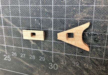
and during waiting the glue drying I filed the two mast foots into form
View attachment 189363
View attachment 189365
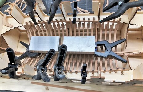
Yesterday evening I was able to install and fix the rest of the normal frames fore and aft.
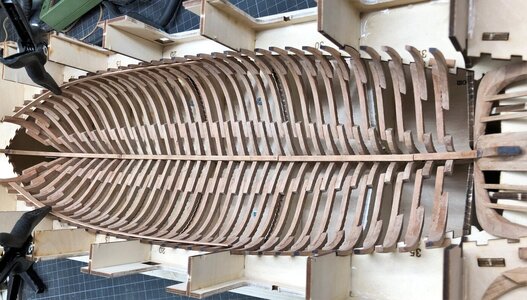
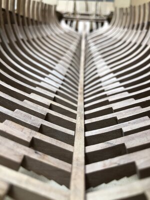
The frames 4, 9 and 33 were sitting a little bit to high and I realized, that my frame teeth were somehow in contradiction with the counter teeth of the jig elements A1, A2 and A6 - what to do? I sanded down the teeth of the A-elements in order to bring the frames down to the keel - now the frames are really more or less following a line and will be well prepared for the inner planking in package 2 of the kit.
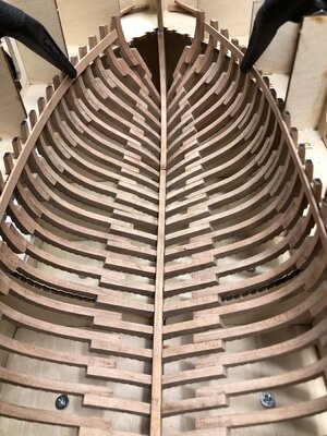
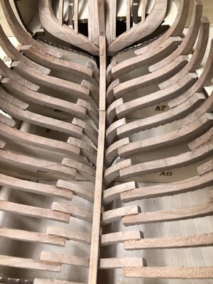
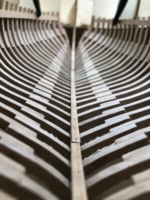
The photos were all made with my mobile, but when everything is finished I will make some shots with my "real" camera in order to get enough depth of field - but these views are nice, or?
BTW: the keelson elements are not fixed
Many Thanks for your interest .... to be continued .....

The frames 4, 9 and 33 were sitting a little bit to high and I realized, that my frame teeth were somehow in contradiction with the counter teeth of the jig elements A1, A2 and A6 - what to do? I sanded down the teeth of the A-elements in order to bring the frames down to the keel - now the frames are really more or less following a line and will be well prepared for the inner planking in package 2 of the kit.


The photos were all made with my mobile, but when everything is finished I will make some shots with my "real" camera in order to get enough depth of field - but these views are nice, or?
BTW: the keelson elements are not fixed


Many Thanks for your interest .... to be continued .....
Mann Uwe, einfach fesch. It simply looks great, very accurate. Absolutely diligent the man. I still have something in front of me.
Looks very good Uwe 
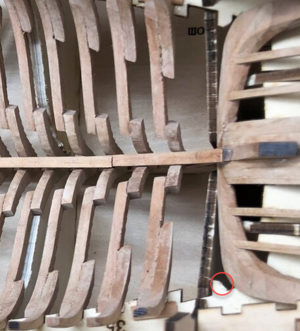
I have been reluctant to glue the stern structure because I realized there is no way I'll be able to get the keel in and out of the building berth once this is done. The middle stern timber as well as the lower transom is locked in upward direction and the side-counter-timbers (or whatever they are called ) will be locked so it cannot be moved either sideways or forward. I have been really puzzled how the heck you took it out again. Now I have just notices some mods. you have done to the berth (red circle) and I wonder if these mods was made after you glued the side-counter-timbers and if this mod. is the reason you were able to take the keel out?

I have been reluctant to glue the stern structure because I realized there is no way I'll be able to get the keel in and out of the building berth once this is done. The middle stern timber as well as the lower transom is locked in upward direction and the side-counter-timbers (or whatever they are called ) will be locked so it cannot be moved either sideways or forward. I have been really puzzled how the heck you took it out again. Now I have just notices some mods. you have done to the berth (red circle) and I wonder if these mods was made after you glued the side-counter-timbers and if this mod. is the reason you were able to take the keel out?

Correct - I removed this small part (which is not really necessary for the future work) and than it is possible to remove.....it was only a question of maybe one milimeter missing.Looks very good Uwe
I have been reluctant to glue the stern structure because I realized there is no way I'll be able to get the keel in and out of the building berth once this is done. The middle stern timber as well as the lower transom is locked in upward direction and the side-counter-timbers (or whatever they are called ) will be locked so it cannot be moved either sideways or forward. I have been really puzzled how the heck you took it out again. Now I have just notices some mods. you have done to the berth (red circle) and I wonder if these mods was made after you glued the side-counter-timbers and if this mod. is the reason you were able to take the keel out?
View attachment 189531
I remember also some other thing, which will help or make it possible:
Take a look at these photos
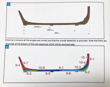
The small "tab" under the stern was once broken away by accident - marked with red arrow
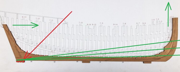
To remove the keel with the complete stern structure I lifted the structure on the bow side Green arrow on the right, so that the keel had approximately the location like with the green lines, just enough that the keel can move forwards over the horizontal layer of the jig
and than you can carefully move the complete structure fore.......
Sorry I forgot to mention the missing tab under the keel
Hi Uwe,
Good to see you were working from home yesterday, hope you are all OK, we sometimes live in a crazy world.
Your Coureur is coming along very nice, with this complicated frame contruction she looks to be a very intriguing build.
Good to see you were working from home yesterday, hope you are all OK, we sometimes live in a crazy world.
Your Coureur is coming along very nice, with this complicated frame contruction she looks to be a very intriguing build.
Hallo Maarten,Hi Uwe,
Good to see you were working from home yesterday, hope you are all OK, we sometimes live in a crazy world.
Your Coureur is coming along very nice, with this complicated frame contruction she looks to be a very intriguing build.
many thanks for your kind words - also to everybody writing PMs . It is a crazy time
Much appreciated
Often it is good, to make a small break of one evening without glue and to read manuals studying drawings and also looking on other building logs to understand the next upcoming working steps completely.......
This I did yesterday evening, although I was not able to finalize - still trying to understand what will be the best order of works to get the best result.
I found also some photos from Tom @CAFmodel in the "Kit-Development-Topic"
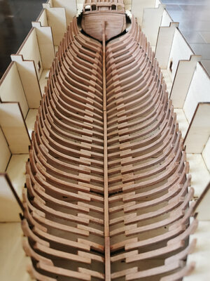
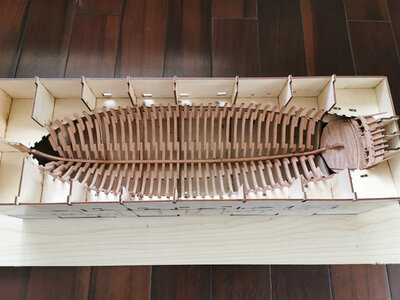
Here we can see, that he installed the inner planking of the stern before the last frames at the bow as well frame 37 are not installed
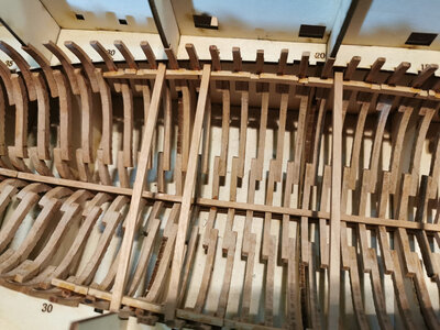
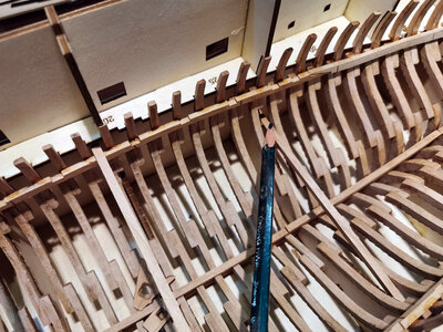
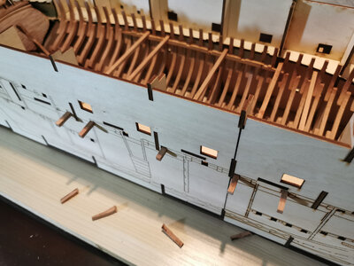
and here we can see, that he installed already the deck clamps, also before installation of the last frames
Based also on this I was thinking, that it is maybe vise to install the small frame on axis 37, 38, 39 an also the bow after the deck clamps are fixed - just to get a correct form to define better the final location and level (especially for axis 3, 2 and 1 ........
I am just thinking, the drawings here are not completely clear showing everything, so the modeler has to think about it -> I like this kit very much !!!
This I did yesterday evening, although I was not able to finalize - still trying to understand what will be the best order of works to get the best result.
I found also some photos from Tom @CAFmodel in the "Kit-Development-Topic"
Caf Model - New Kit - 1/48 Le Coureur 1776
I haven't been online for a long time. I've been making coureur recently. The latest design, the latest slipway.I hope you like it It is expected to be available in July and August, Price: 342,
shipsofscale.com


Here we can see, that he installed the inner planking of the stern before the last frames at the bow as well frame 37 are not installed


and here we can see, that he installed already the deck clamps, also before installation of the last frames
Based also on this I was thinking, that it is maybe vise to install the small frame on axis 37, 38, 39 an also the bow after the deck clamps are fixed - just to get a correct form to define better the final location and level (especially for axis 3, 2 and 1 ........
I am just thinking, the drawings here are not completely clear showing everything, so the modeler has to think about it -> I like this kit very much !!!


