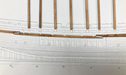
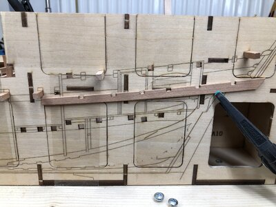
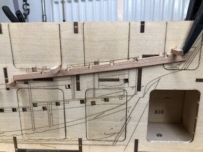
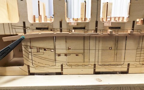
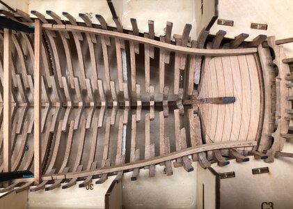
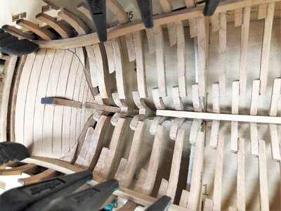
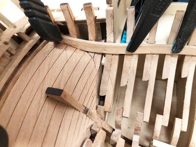
LE COUREUR - french Lugger 1776 - POF kit from CAF in 1:48 by Uwe

In order to understand more, I opened box No.2 of the kit and tried out the principle of the "measuring sticks" to get the correct levels for the deck clamps

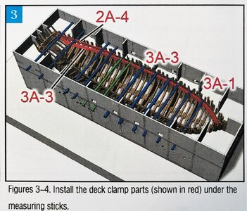
Let us take a look at the manual and the shown sketches in which the use of these measuring sticks are shown
For the deck clamps picture 3 is important with the blue and green marked sticks
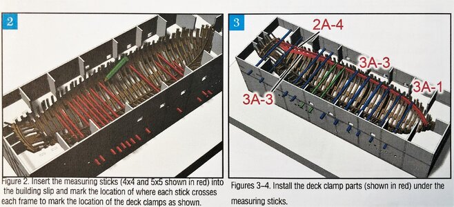
IMG-4871.jpg

Therefore to try the method I had to close the "windows" of the jig, like described in post #109 of this topic

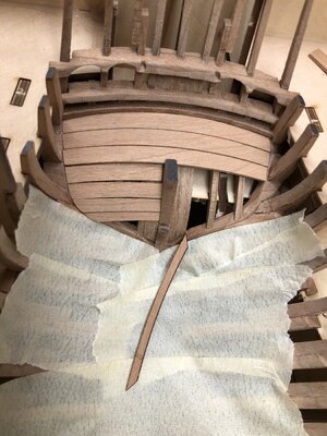
I used transparent adhesive tape, so I can see the laser markings and most important the open quare to take over the sticks - With the tape the parts ("window doors") are fixed enough for these activities and you can easily remove them when not necessary any more
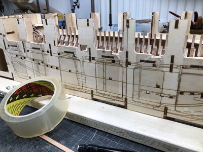
IMG-4866.jpg

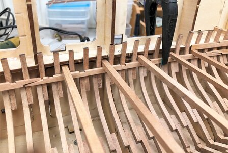
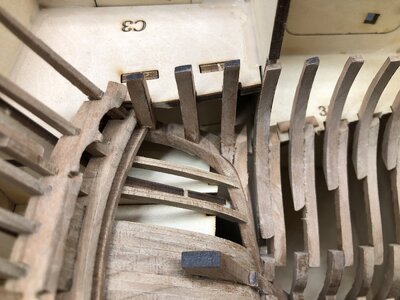
some measuring sticks installed - without any correct order
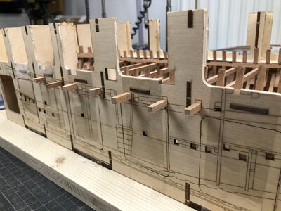
IMG-4867.jpg

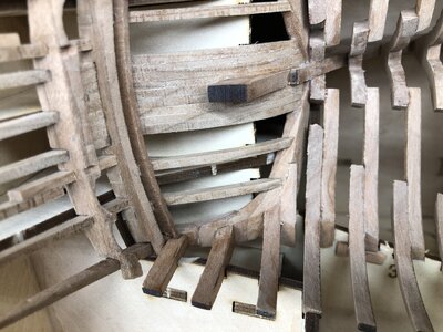
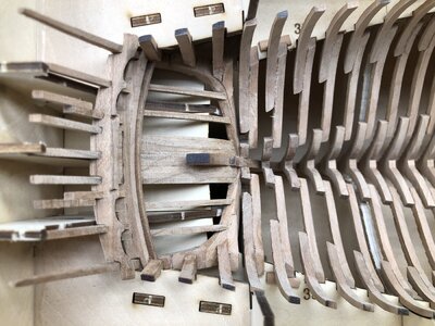
and the three parts of the deck clamps (parts 3A-1, 3A-2 and 3A-3) are laying there on top of the sticks - only to understand the ideas of the construction methods behind -> I think, step by step, that this can be also a real clever idea - I hope to confirm this opinion in some days
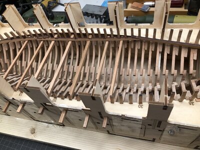
IMG-4868.jpg

IMG-4869.jpg

Remark:
Do not search in the box for the total number of measuring sticks shown in the manual - you have to reuse them in several axis.
The box contents 2 times 4*4*400 and 2 times 5*5*400
Cutting them to the length of 200mm - so you get 4 measuring sticks of both dimensions (4*4mm and 5*5mm) with length of 20cm

This evening I have to think further - and I hope that Tom @CAFmodel can give also some advise ..... :cool:
 
and the three parts of the deck clamps (parts 3A-1, 3A-2 and 3A-3) are laying there on top of the sticks - only to understand the ideas of the construction methods behind -> I think, step by step, that this can be also a real clever idea - I hope to confirm this opinion in some days
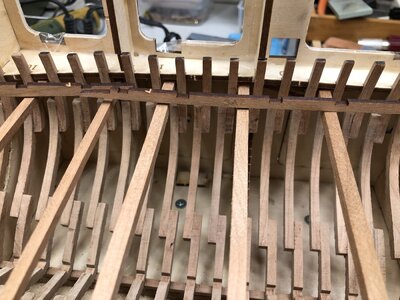
Looks like a quite smart idea by CAF!

for the "final" Installation don't forget the Instruction (Picture 3) call to place the deck clamps "under" the measuring sticks, not "on top" of them! That also was my Problem when going through the Manual in Picture 2: mark where the sticks cross the Frame... mark what? the top? the Bottom? Middle? … but now it seems "Bottom" is meant ;)
You can see the instalation of the deck clamps on the lasered template on the side of the jig. This kit looks very well thought through.
 
Looks like a quite smart idea by CAF!

for the "final" Installation don't forget the Instruction (Picture 3) call to place the deck clamps "under" the measuring sticks, not "on top" of them! That also was my Problem when going through the Manual in Picture 2: mark where the sticks cross the Frame... mark what? the top? the Bottom? Middle? … but now it seems "Bottom" is meant ;)
Hallo Markus,
many thanks for your words and also the hint.
On the photo you mentioned the clamps were laying only on top - I will show in the next post (soon) how these parts will be installed - I am still struggling with the correct sequence of working steps.......but I am close to a decision
 
By
Hallo Markus,
many thanks for your words and also the hint.
On the photo you mentioned the clamps were laying only on top - I will show in the next post (soon) how these parts will be installed - I am still struggling with the correct sequence of working steps.......but I am close to a decision
i have been doing the same (will post my progress soon but have been too busy with work). I have been trying and considering the inside stern planking as a next step
 
In order to show everybody a little bit more in detail the clever method with working these measuring sticks.

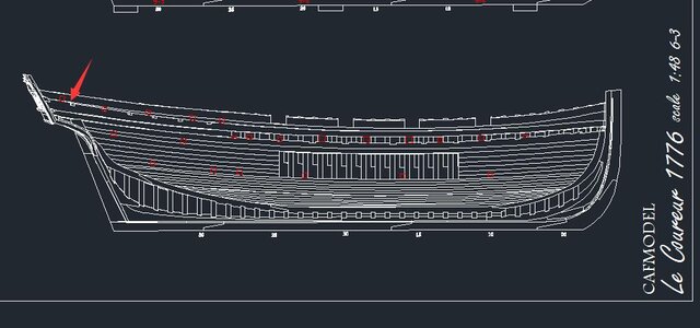
Here you can see the sticks on the correct location marked on the drawing with red squares
IMG-4874.jpg

To explain it a little bit further I show these clamps also on the outside of the jig - clamp is lower than the final position, so that you can recognize the final location on laser painting
IMG-4875.jpg

Here in the correct height
IMG-4876.jpg

IMG-4878.jpg

IMG-4879.jpg

all four clamps of one side
IMG-4883.jpg

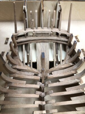
and also inside the hull
IMG-4884.jpg

IMG-4885.jpg

IMG-4886.jpg

Many Thanks for your interest ..... to be continued
 
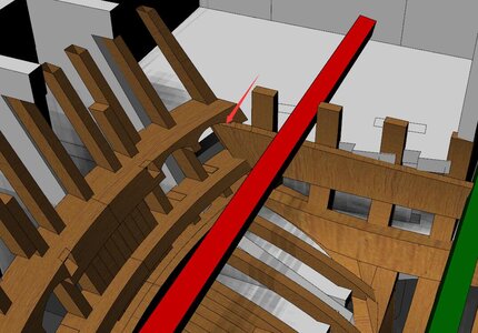
Note here that ,it will affect the aft deck
It can be checked in plan3
View attachment 191584
View attachment 191585
Hallo Tom.
many thanks for the hint and the additional information - such detail 3D-sketches and drawings are helping very much, so when ever you think - please give us further assistance with such.

My next working step was the installation of the "frames axis 37 up to 40 (I think) - It seems that they are important for the later fixing the clamps...
IMG-4887.jpg

IMG-4888.jpg

IMG-4889.jpg

IMG-4890.jpg
 
In order to show everybody a little bit more in detail the clever method with working these measuring sticks.

Here you can see the sticks on the correct location marked on the drawing with red squares
View attachment 191051

To explain it a little bit further I show these clamps also on the outside of the jig - clamp is lower than the final position, so that you can recognize the final location on laser painting
View attachment 191052

Here in the correct height
View attachment 191053

View attachment 191054

View attachment 191055

all four clamps of one side
View attachment 191056

and also inside the hull
View attachment 191057

View attachment 191058

View attachment 191059

Many Thanks for your interest ..... to be continued
Very clever jig for properly aligning deck clamps. Lovely work.
 
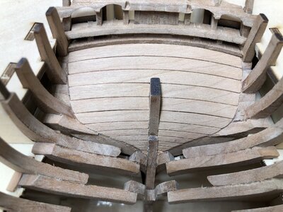
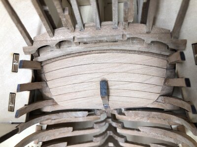
The next step I did, was the inner planking of the stern area

Dry-fitted
PS: a small tip,: after two times a small piece was falling between the frames inside the jig, I covered the gaps between the frames with some masking tape, so that the pieces can not be lost in the "nirvana" of the jig - it is not so easy to get them out
IMG-4891.jpg

Finished
IMG-4892.jpg

IMG-4893.jpg

Many Thanks for your interest ... to be continued .....
 
Many Thanks to all friends following this building log - and many thanks for the comments, kind words and likes

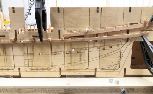
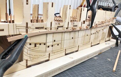
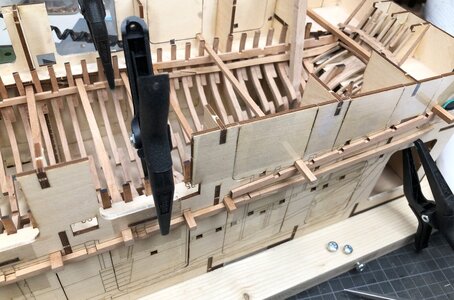
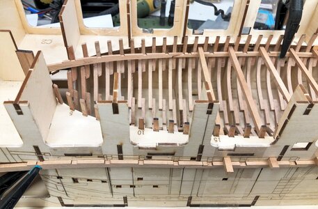
The next step was the installation of the clamps shown in this sketch - (Remark: the middle part has the correct number 3A-2 and not 3A-3!)IMG-4871a.jpg

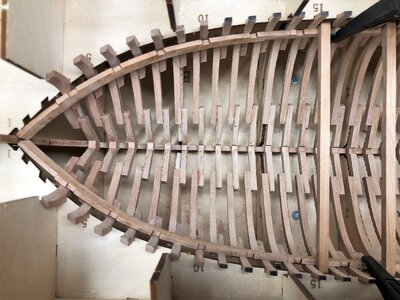
First of all the deck-clamp from the bow towards the stern - for easier adjustment I watered the parts for some time and adjusted the form with a heating iron / electric plank bender (from Kolderstock)

The parts are here dry-fitted
3A-1:
IMG-4895.jpg

3A-3:
IMG-4894.jpg

waiting that the glue is hardening
IMG-4899.jpg

IMG-4900.jpg
 
Back
Top