
A very good presentation of cargo and hold! Bravo, Mon Amie! 

 |
The beloved Ships in Scale Magazine is back and charting a new course for 2026! Discover new skills, new techniques, and new inspirations in every issue. NOTE THAT OUR NEXT ISSUE WILL BE July/August 2026 |
|
 |
As a way to introduce our brass coins to the community, we will raffle off a free coin during the month of August. Follow link ABOVE for instructions for entering. |
|


.jpg")


Looks fantastic Uwek!Once more many many thanks for your feedback and your likes - highly appreciated
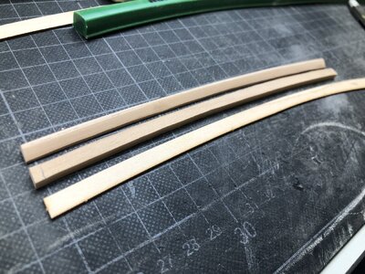
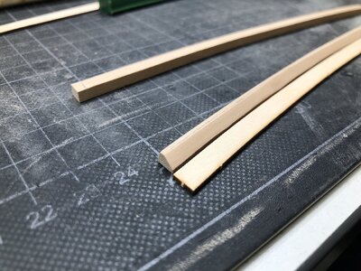
After fixing of the cargo it was possible also to finally install the beams at this area
In the first photos still dry fitted
View attachment 234238
here also the top view of the situation
View attachment 234239
- Important here is the correct location and angle of the mast partners of the main mast - I checked the angle with an approximate comparison with the drawing - the final angle has to be finetuned and adjusted later on with installing the wooden wedges and fixing of the main mast.....
View attachment 234240
Now the beams are fixed and also the boards on top of the ballast box are finally fixed
I arranged the boards in such a way, that all boards theoretically necessary for complete coverage of the box are visible - something like, that one seaman has to check the ballast room and removed two of the long boards and on one side the short boards on the left side of the mast foot box.
With this arrangement, the stone ballast is visible and there is enough free space for the anchor cables later on
View attachment 234241
Here for additional explanation, what I mean are two images from the CAF model showing the cables
View attachment 234244 View attachment 234245
View attachment 234242
View attachment 234243
Many Thanks for your interest ..... to be continued .....


Good idea with the "making of" an axe - I will try something - although it will be hard to see at the end (but I (and you) will know, that the axe is there.......Hi Uwe, wonderful work again.
The axe you can make yourselve from some copper or lead sheet or even wood with aluminium tape or rust paint.
In the galley onboard of Alert coal was used as there is a coal storage on the drawings. Where the French using fire wood for their furnace?
Oh ja - the sad part started already with planing how to plank the deck - which areas will stay open or planks which will be not installed, so you can see something of the interior ......Terrific stuff. Now the sad part comes when you have to cover half of it.


It is very good idea, although I think, that it will be slightly more complicated with the Coureur than with the Alert.Lovely work, just a thought thinking ahead, would it work trying to do them same as Maarten has done on his Alert and split hull (don't know technical name for it) when I get round to starting le courier. So you can see the detail inside? Regards


I agree absolutely with Jim.I like your waterway's solution, Uwe.
So you are saying that the 4x4 pear is shaved then incorporated with the planking instead of plunked on top as per plans. That is all too sensibly correct but 'sigh...'
too late for me. I do have to slow down a bit.


")
