LE COUREUR - french Lugger 1776 - POF kit from CAF in 1:48 by Uwe

Changing the waterways, like I did, will produce some necessary adjustments of the planking, which will try to explain in the following


all planks are laying on the deck (without waterways (here you can see once more the mixing of the planks because of the wood grain and annual rings)
IMG-6344.jpg

This photo is showing the deck planking with the original kit waterway
IMG-6331.jpg

you can see, that because of the bigger width of the waterway-plank the center of the planking is moved out of the center -> when you use the kit waterline you have to adjust this with reducing the width of the waterway plank
IMG-6332.jpg

IMG-6333.jpg

here the planking is centered and you can see the approximate area, which has to be reduced - mainly at the area towards the bow, midships it is fitting very well
IMG-6334.jpg

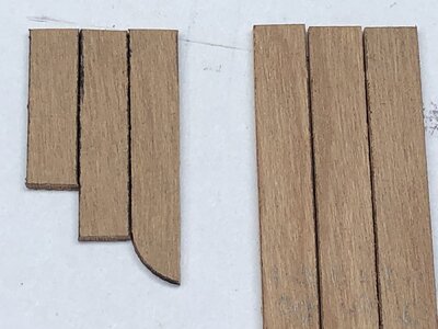
Now my alterantive waterway -shown are the dryfitted waterways close to the framing
IMG-6346.jpg

IMG-6347.jpg

and here you can see the planking centered and also the alternative waterway at its place -> and you can see some gaps between the planking and the waterway
For comparison reason you can see the original kit waterway at the center of the photo
IMG-6348.jpg

IMG-6349.jpg

IMG-6350.jpg

appr. at this location the gap between the frames and the planking has the same width of my alternative waterway. From midship to this location I have to widen the planking to fill the gap, and from here towards the bow the planking can be sanded and adjusted to fit in. As I mentioned already my waterway has a continuous width of 4mm
IMG-6336.jpg


and here the alternative waterway with all planks (dryfitted) layed on the deckbeams
IMG-6351.jpg

This I am showing, that everybody who wants to change or adjust the waterway, should be aware, that you have also to adjust the last outer planks
So still some works to do
Because of this, I mentioned in one earlier post, that the planking job will need some time to build ......

to be continued ......
 
Today a short update on the planking works

First I tried first time the use of the ECOLINE paints to immitate the caulking

Here some trials with the same wood used for the hatches - on the right side without Ecoline, on the left painted with black Ecoline

IMG-6288.jpg

and here the result on the deck planking wood
IMG-6352.jpg

I was happy with the final result, so I decided to use the "Ecoline-technique" on the complete deck planking of my Coureur

I painted both contact sides of the planks

This photo is showing the first group of planks -> Due to the fact, that Ecoline is waterbased the wood glue is getting also black.
YES - It is looking terrible, but wait until you see the final result
IMG-6359.jpg

Here the same planks after scratching

IMG-6360.jpg

IMG-6361.jpg


and the planks on the deck - here the center part is finished, the planks parallel to the waterways are only fixed with adhesive band
IMG-6362.jpg

IMG-6363.jpg

IMG-6365.jpg

I am happy with the result, the caulking line is looking in my opinion realistic - definitely it is faster and easier than to handle thin paper between the planks

IMG-6366.jpg
 
Many Thanks once more for the kind wrds, comments and like received - much appreciated and a real motivation.
I know, that sometimes it is a little bit boring, but as mentioned earlier already, this log should also help the modeler of the same kit to see how to do or not to do some details.......

Before gooing further with the deck planking works, I decided to make also the hatch and hatch covers (this ship had no gratings at all)

as usual you can see the sketches of the manual, so you can understand to work in a better way

First of all the main hatch over the cargo room
IMG-6279.jpg

and here you can see the detail in the Boudriot nonograph
IMG-6287.jpg

BTW: visible is the detail, that the hatch frame is sitting on top of the planking and not on the beam

The elemnts are in such a way prepared, that it will be possible, that all hatch covers can be opened and closed
-> one additional way to have an additional insight into the hull to see the interior works of the finished model :cool:

I made a first trial how to immitate the caulking between the boards of the cover - here I used also the pens of Ecoline - BTW: very easy to apply
on the right you see without - on the left with "caulking"
IMG-6288.jpg


the first cover is started with the boards
IMG-6290.jpg

The bottom view with the started framing
IMG-6291.jpg

The top view
IMG-6292.jpg

With the help of the cover also the hatch frame was produced - somehow I used the cover as a jig for the correct dimensions
IMG-6293.jpg

The hatch at the correct place (still fitted dry)
IMG-6295.jpg

and the hatch with closed cover
IMG-6296.jpg
 

Attachments

  • IMG-6289.jpg
    IMG-6289.jpg
    180.8 KB · Views: 3
And now the other remaining hatches and hatch covers have to be prepared

IMG-6297.jpg
(remark: please be aware, that the parts 1Y-3 are numbered wrong: correctly it should be written 1Z-3)

This is hatch No. 68
IMG-6302.jpg

and the same opened - later on a ladder is installed under this hatch, so that the ships-cook can easily bring the captain a cup of coffee
IMG-6303.jpg


hatch No. 69
IMG-6310.jpg

and also shown open - here I installed a monkey ladder
IMG-6308.jpg

and finally hatch No. 70 which will be installed directly infront of the rudder - it is the smallest hatch cover
IMG-6311.jpg

Finally you can find photos of the four hatches with hatch covers for an overview and comparison of sizes and the way of construction - all four hatches are different in the way they are constructed, therefore I show them all visible from different persepctives

Hatches and hatch covers separate:

IMG-6312.jpg

IMG-6313.jpg

IMG-6317.jpg

IMG-6314.jpg


and closed

IMG-6315.jpg

IMG-6316.jpg

IMG-6318.jpg
Remark: hatch No. 70 is here on the wrong place and should be more aft - on this (wrong) location a skylight has to be installed

The hatches on top of the Boudriot drawing
IMG-6325.jpg

and on top of the CAF drawing
IMG-6326.jpg
Remark: you can see that the drawing is showing hatch No. 70 bigger than the model-hatch - this small error in the drawing will be revised in future releases of the kit -> the kit is correct, only the drawing is wrong

In order to see the contrast between the planking timber and the hatch timber
IMG-6364.jpg


Still missing are the eyebolts and triangle rings for lifting the cover - will be done later -> now it is important to have the hatches for the correct dimension of the openings in the deck planking
 

Attachments

  • IMG-6319.jpg
    IMG-6319.jpg
    107.5 KB · Views: 7
And now the other remaining hatches and hatch covers have to be prepared

View attachment 236586
(remark: please be aware, that the parts 1Y-3 are numbered wrong: correctly it should be written 1Z-3)

This is hatch No. 68
View attachment 236587

and the same opened - later on a ladder is installed under this hatch, so that the ships-cook can easily bring the captain a cup of coffee
View attachment 236588


hatch No. 69
View attachment 236590

and also shown open - here I installed a monkey ladder
View attachment 236589

and finally hatch No. 70 which will be installed directly infront of the rudder - it is the smallest hatch cover
View attachment 236591

Finally you can find photos of the four hatches with hatch covers for an overview and comparison of sizes and the way of construction - all four hatches are different in the way they are constructed, therefore I show them all visible from different persepctives

Hatches and hatch covers separate:

View attachment 236592

View attachment 236593

View attachment 236597

View attachment 236594


and closed

View attachment 236595

View attachment 236596

View attachment 236598
Remark: hatch No. 70 is here on the wrong place and should be more aft - on this (wrong) location a skylight has to be installed

The hatches on top of the Boudriot drawing
View attachment 236600

and on top of the CAF drawing
View attachment 236602
Remark: you can see that the drawing is showing hatch No. 70 bigger than the model-hatch - this small error in the drawing will be revised in future releases of the kit -> the kit is correct, only the drawing is wrong

In order to see the contrast between the planking timber and the hatch timber
View attachment 236601


Still missing are the eyebolts and triangle rings for lifting the cover - will be done later -> now it is important to have the hatches for the correct dimension of the openings in the deck planking
A wonderful primer on hatch cover construction Uwe.
 
Before further working on the deck planking it is still necessary to install the last beam and the carlings close to the stern of the vessel.
But before I can do this I decided to drill and open the hole for the rudder

First drilling a smaller diameter, afterwards with a bigger diameter and the rest was done with different types of my rasps and files

view from inside the hull
IMG-6397.jpg

IMG-6399.jpg

and from outside - later on, when the rudder is finally installed the rudder hole will be covered and closed against "splash water" with a fine leather (which is included in the kit fittings - btw: very good material
IMG-6398.jpg


Here you can see the test with the main rudder parts, which have to pass the hole
IMG-6396.jpg

IMG-6395.jpg

I am in moment not 100% sure about the size of the hole, if it is big enough to let the rudder turn - but the total size can be easly adjusted and widened also afterwards. Now it was time to install also permanently the last beam and carlings (no photos made)
 
After the last bea, is installed, the planking works on the upper deck can be started

First work was the installation of my "alternative" waterway (lengthy description of my thoughts about waterway you can find several posts earlier)

IMG-6403.jpg

IMG-6402.jpg

IMG-6402a.jpg

You can recognize already three planks installed with the waterway

I will not install all planks, but will leave some area, so that you can see a little bit the interior under the deck

Here waterways and the planks close to them (2 and 3 shorter planks) are fixed, the middle part and the single planks are only dry fitted
Before fixing these planks several works have to be done before - but you get an impression, how it will look like
IMG-6400.jpg

IMG-6404.jpg

With this (not very good made) photo I checked the visibility through the frames - enough light through the space between the planks so something is visible
IMG-6401.jpg


Mayn Thanks for your interest .... to be continued
 
Before cutting the openings into the deck planking and also before sterting the treenailing of the deck I decided to prepare also the deck-superstructures.
There are two lighthouses and also the staircase descent (hope this term is correct)

IMG-6505.jpg

As usual the three capters with sketches in the manual in oder to understand the works better

First small project inside the project was the staircase structure with skylight

IMG-6502.jpg

IMG-6503.jpg

Let us start - these here are the parts for the structure 84
IMG-6429.jpg

After some very light sanding the brass window frame was fitting exactly inside the opening of the wall elements
IMG-6430.jpg

IMG-6431.jpg

The two wall elements with the window frame (after blackening) from inside
IMG-6443.jpg

and the same with view from outside
IMG-6444.jpg

I was afraid, that the transparent folio (included in kit) could get "foggy" with using superglue, so I decided to use double sided adhesive tape -it worked very well and is not visible later on
IMG-6445.jpg

The elemnt installation on top of an double sided adhesive tape - this tape is helping very much to keep the elements in place until the wood glue is dry
IMG-6446.jpg

the wall at the left has to be removed later on, after the roof boards are fixed
IMG-6447.jpg

First deck structure is prepared
IMG-6448.jpg

IMG-6449.jpg

Here you can see, that also the temporary wall is removed
IMG-6474.jpg

view from the backside
IMG-6475.jpg

and both sitting ion the correct place
IMG-6477.jpg

at the end, I want to show the doors open to be able to look down the staircase
IMG-6480.jpg
 
Before cutting the openings into the deck planking and also before sterting the treenailing of the deck I decided to prepare also the deck-superstructures.
There are two lighthouses and also the staircase descent (hope this term is correct)

View attachment 237614

As usual the three capters with sketches in the manual in oder to understand the works better

First small project inside the project was the staircase structure with skylight

View attachment 237611

View attachment 237612

Let us start - these here are the parts for the structure 84
View attachment 237615

After some very light sanding the brass window frame was fitting exactly inside the opening of the wall elements
View attachment 237616

View attachment 237617

The two wall elements with the window frame (after blackening) from inside
View attachment 237618

and the same with view from outside
View attachment 237619

I was afraid, that the transparent folio (included in kit) could get "foggy" with using superglue, so I decided to use double sided adhesive tape -it worked very well and is not visible later on
View attachment 237620

The elemnt installation on top of an double sided adhesive tape - this tape is helping very much to keep the elements in place until the wood glue is dry
View attachment 237621

the wall at the left has to be removed later on, after the roof boards are fixed
View attachment 237622

First deck structure is prepared
View attachment 237623

View attachment 237624

Here you can see, that also the temporary wall is removed
View attachment 237625

view from the backside
View attachment 237626

and both sitting ion the correct place
View attachment 237627

at the end, I want to show the doors open to be able to look down the staircase
View attachment 237628
absolutely amazing Thumbsup Thumbsup :)
 
Many Thanks for your kind comments and the likes received - much appreciated

Missing is the third small skylight which will be installed on top of the captains room

IMG-6504.jpg

glued but not cleaned and without final sanding
IMG-6481.jpg

IMG-6482.jpg

IMG-6483.jpg

after final sanding on top of the final palce
IMG-6510.jpg

on top of the deck planking - now it is time to start the cut of the different deck openings
IMG-6511.jpg

IMG-6513.jpg

IMG-6516.jpg

pre shaped openings
IMG-6512.jpg

but before the final shaping of the openings I have to fix the planking on top of the beams, and before this, I decided to make also as much as possible of the treenailing of the deck planking -> step by step

to be continued with the treenailing works - coming soon
 
Уве, добрый день. У меня вопрос. Крышка люка на этом фото наклеена? Если это так, возможно, стоит снять фаску в этих местах для более плотного прилегания облицовочных панелей.

Uwe good afternoon. I have a question. Is the manhole cover glued in this photo? If this is the case, it may be worth chamfering these areas to make the cladding fit snugly.
IMG-6482.jpg
 
Last edited by a moderator:
Уве, добрый день. У меня вопрос. Крышка люка на этом фото наклеена? Если это так, возможно, стоит снять фаску в этих местах для более плотного прилегания облицовочных панелей.

Uwe good afternoon. I have a question. Is the manhole cover glued in this photo? If this is the case, it may be worth chamfering these areas to make the cladding fit snugly.
View attachment 237748
Many Thanks for your comment, and it is good, that you asked this - A very good point and important

What you see is an optical illusion, better a different interpretation of what you see

Unbenannt.jpg

I guess with chamfering you mean, that I should sand the boards of the roofs in this way, or?

I did

What you see are the small displacements of some mycro millimeters - as mentioned the photo was made before the final sanding an adjustments (but with fixed and glued roof boards
IMG-6482a.jpg

Unbenannta.png

On this building you can see them also slightly, but after sanding the ends of the roofs you can see not anymore the gap
IMG-6475a.jpg

With this overview you can see, that I made the chamfering of the boards
IMG-6516a.jpg

A very good point and for the final appearance very important !
 
Last edited:
Hi Uwe, I am not a member of this build group so I have been reluctant to post. But I have to say that your work is exemplary at every level. I love to watch from the sidelines learning what can be accomplished by an experienced builder who loves the hobby enough to share all his secrets with other builders. Your attention to detail and hand-skills to build those details puts you in the top tier in my opinion. Bravo!
 
Hi Uwe, I am not a member of this build group so I have been reluctant to post. But I have to say that your work is exemplary at every level. I love to watch from the sidelines learning what can be accomplished by an experienced builder who loves the hobby enough to share all his secrets with other builders. Your attention to detail and hand-skills to build those details puts you in the top tier in my opinion. Bravo!
Hi Paul, that's exactly it and not everyone can convey it the way Uwe does.
 
Many Thanks for your kind comments and the likes received - much appreciated

Missing is the third small skylight which will be installed on top of the captains room

View attachment 237741

glued but not cleaned and without final sanding
View attachment 237738

View attachment 237739

View attachment 237740

after final sanding on top of the final palce
View attachment 237742

on top of the deck planking - now it is time to start the cut of the different deck openings
View attachment 237743

View attachment 237745

View attachment 237746

pre shaped openings
View attachment 237744

but before the final shaping of the openings I have to fix the planking on top of the beams, and before this, I decided to make also as much as possible of the treenailing of the deck planking -> step by step

to be continued with the treenailing works - coming soon
Dear Uwe
The construction / creation process you presented and the result are very beautiful and instructive, well done and thanks for sharing
 
Once more many thanks for your kind comments, hints and likes - it is realy motivating to procede in this manner (the modeling and also the log)

The next step I jumped in was the treenailing of the deck planking.
Often we have the discussion, if a model should have deck-treenailing - some modeler have the opinion, that treenails in the model should not be made, due to the fact, that on real ships, the nails were made out of the same timber like the planks, so the nails would not be visible, especially in a model scale. This is correct.
On the other hand, as a modeler is his own "artist" in creating the appearance of his model, at the final end, it is a pure question of taste.
I usually make treenails, often as fake nails with some wood putty or similar with a slightly different color like the planks.

Here on the Le Coureur model I tried it first time to use simple toothpicks, which have originally a similar color like the kit planking wood.

So making first a sample planking and used also some different Ecoline paints for the peak

IMG-6521.jpg

The three rows on the left with black, the two rows in center without additional color and the two on the right with some ochre
IMG-6520.jpg

(now the sample is turned by 180°)
IMG-6522.jpg

and these are the final results of the treenail samples after scraping and sanding
IMG-6523.jpg

with black paint - very good result, but very dominant
IMG-6526.jpg

looks dirty - maybe also the exacution was not done with accuracy - because from the beginning I had already my favourite
IMG-6525.jpg

my favourite solution - toothpicks without any treatment, only a very small volume of wood glue on the peak before I hit the pick into the predrilled hole (0,5mm)
IMG-6524.jpg
 
Back
Top