My personal taste is in line with Tobias', nevertheless you are continuously doing an excellent job with this build Uwe. One question: The nails in the stern planks are they simulated? (just holes?)
-

Win a Free Custom Engraved Brass Coin!!!
As a way to introduce our brass coins to the community, we will raffle off a free coin during the month of August. Follow link ABOVE for instructions for entering.
-

PRE-ORDER SHIPS IN SCALE TODAY!
The beloved Ships in Scale Magazine is back and charting a new course for 2026!
Discover new skills, new techniques, and new inspirations in every issue.
NOTE THAT OUR FIRST ISSUE WILL BE JAN/FEB 2026
- Home
- Forums
- Ships of Scale Group Builds and Projects
- Le Coureur 1776 1:48 PoF Group Build
- Le Coureur 1776 1:48 Group Build Logs
You are using an out of date browser. It may not display this or other websites correctly.
You should upgrade or use an alternative browser.
You should upgrade or use an alternative browser.
LE COUREUR - french Lugger 1776 - POF kit from CAF in 1:48 by Uwe
Yes, these nails at the transom are only simulated with some pressed holes done with a scriber.One question: The nails in the stern planks are they simulated? (just holes?)
Tomorrow I will show with a photo why I did this in this area.....
Just to explain shortly this decision with simulating the nails and not making real copper nails like at the rest of the hull plankingMy personal taste is in line with Tobias', nevertheless you are continuously doing an excellent job with this build Uwe. One question: The nails in the stern planks are they simulated? (just holes?)
The planking of the stern transom is only around 1mm (or less) thick (originally 1,5mm, but I had to sand it partly to fit well.
The upper part of the transom planking is visible from the deck side, because there was no inner planking at this area.
Here you can see the planking of the transom from the "inside" attached to the vertical stern structure - which is only 2mm to 3mm thick
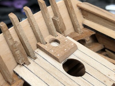
I was very afraid, that it could happen, that for making the copper nails
1) I could drill too deap, so that the holes would be visible inside at the vertical structure
or
2) That I miss the structure with hole in the planking and not enough meat to fix the nail
And I have the feeling, that the small immitated "nails" are looking better at the transom
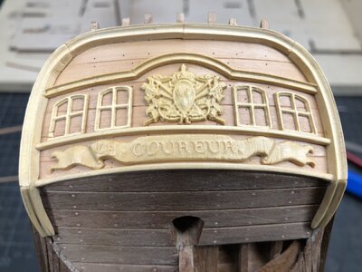
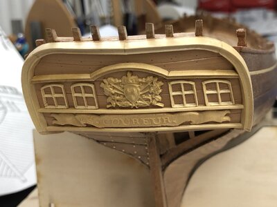
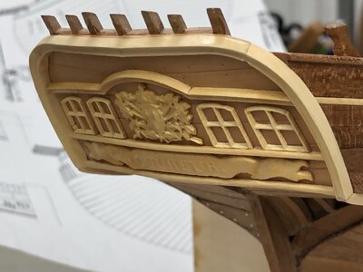
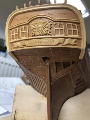
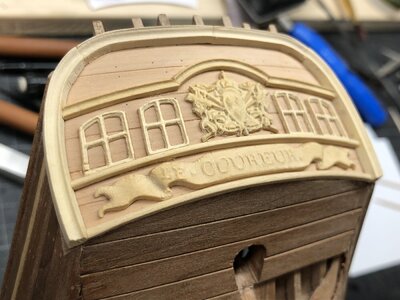
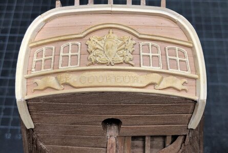
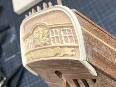
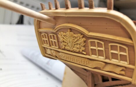
Going further with the ornaments on the transom - in the meantime I have finished them
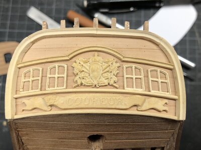
showing them from different perspectives
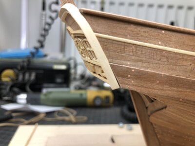
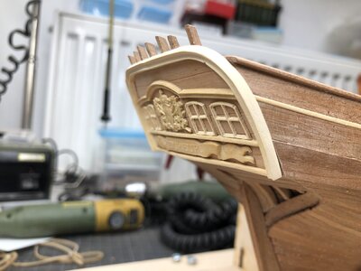
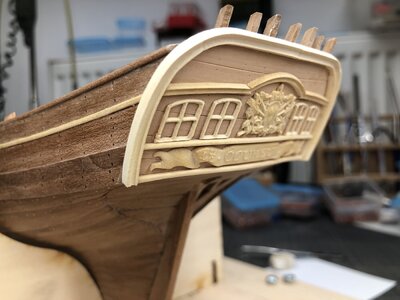
from this perspective (like from a boat on sealevel) the windows are looking straight
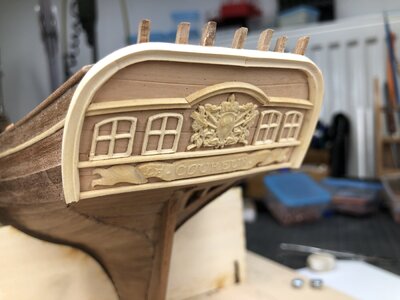
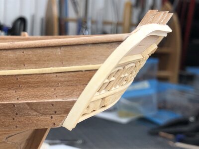
Because of shortening the top rail I had some spare, so I could add some rail under the transom, which was often made at this time
Many Thanks for your interest ...... to be continued ..... f.e. I just realized, that I forgot the nailing on the lower part of the stern (planking around the rudder)

showing them from different perspectives


from this perspective (like from a boat on sealevel) the windows are looking straight


Because of shortening the top rail I had some spare, so I could add some rail under the transom, which was often made at this time


Many Thanks for your interest ...... to be continued ..... f.e. I just realized, that I forgot the nailing on the lower part of the stern (planking around the rudder)
Hallo Uwe, this really turned out very nice, as I said, very coherent. I like this extraordinarily.

Good morning Uwe, great. Now that everything is ready, I really like it. Did you do very well, great result.
A nice build, Uwe. Of this delicate part that is very visible on the ship. The curves have a nice 'composition'.Going further with the ornaments on the transom - in the meantime I have finished them
View attachment 251713
showing them from different perspectives
View attachment 251714
View attachment 251715
View attachment 251716
View attachment 251717
from this perspective (like from a boat on sealevel) the windows are looking straight
View attachment 251718
View attachment 251719
Because of shortening the top rail I had some spare, so I could add some rail under the transom, which was often made at this time
View attachment 251720
View attachment 251721
Many Thanks for your interest ...... to be continued ..... f.e. I just realized, that I forgot the nailing on the lower part of the stern (planking around the rudder)
Regards, Peter
No questions, moldings, and carvings are beautifying the transom, and as always, your work is top-notch. My questions, however (as always  ), how those moldings were attached on the real ship by means of treenails or\and bolts? Will you consider imitate or even make the fastenings on your model?
I think, that due to the fact, that these decorations were only attached and had no structural function, that they were only fixed only with nails and no bolts.......how those moldings were attached on the real ship by means of treenails or\and bolts?
I am still thinking about it and did not make a decision until now - Frölich made some nails on his model, so ......Will you consider imitate or even make the fastenings on your model?
Many Thanks for your kind comments and all the likes received - much appreciated and a motivation to continue this detailed log in similar way
several smaller parts and elements are done in the meantime
mastfoot at the stern
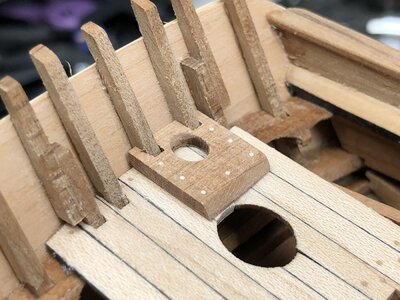
The shheves blocks are done with five wooden elements
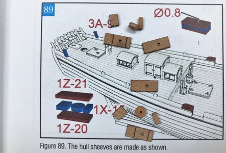
the pully is runnung on an axis and is turning
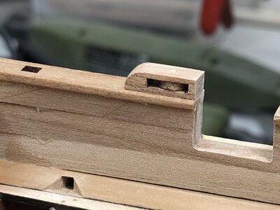
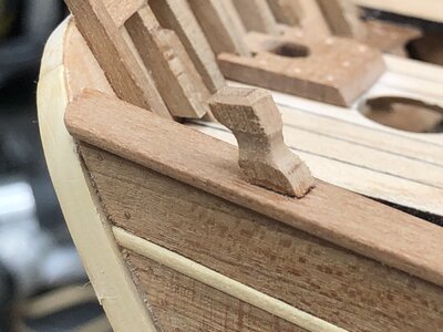
additional "bitt" on top of the rails near stern
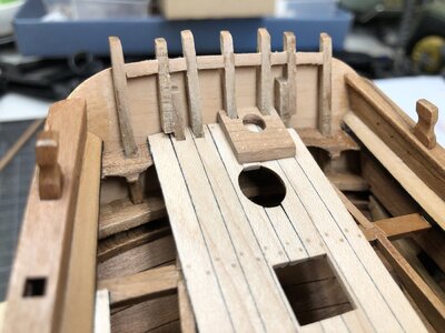
I made also some samller stiffeners between the vertical timbers at the top of the transom - not shown in the drawings, but I guess for structural reasons, they had some on the real ship
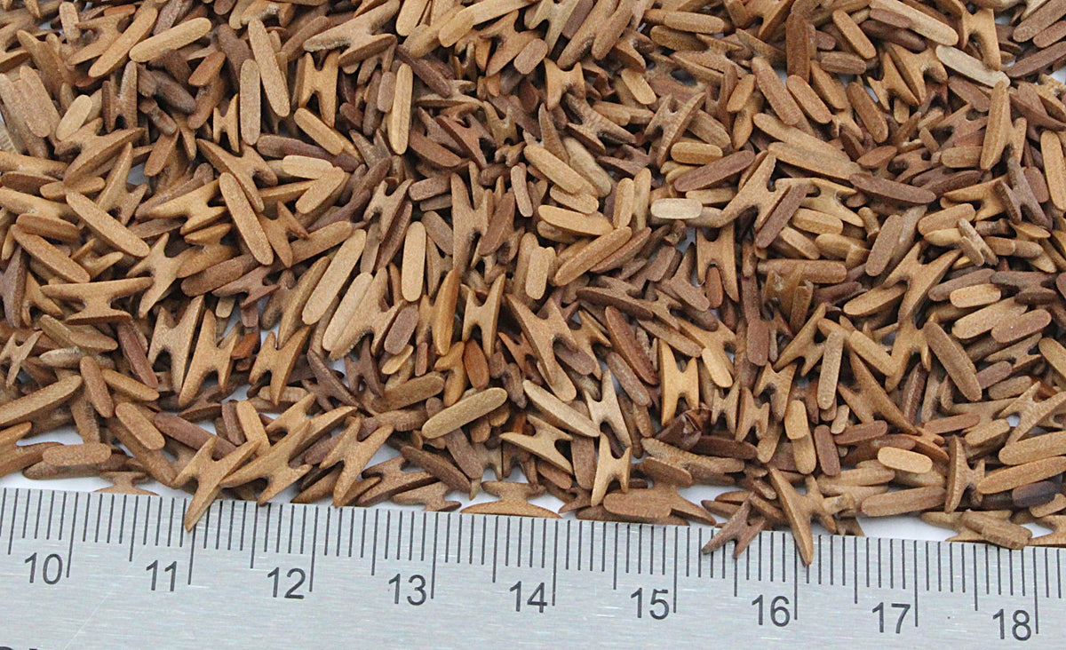
and also the cleats were started
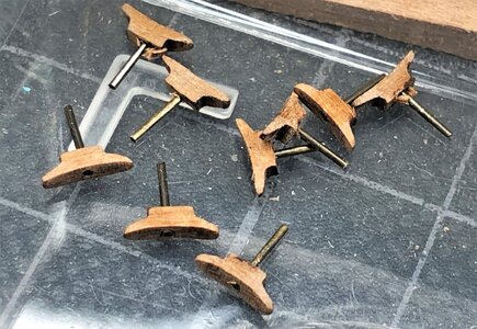
on top you see the untouched cleats right out of the lasered sheet
at the bottom you see some cleats already preliminary sanded into form with also removing the laser char - a lot of work
due to the fact, that I plan to fuloly mast and rigg the model I thought, that it will be better to make in the center a pin, so later on the cleats will be more secured and better fixed - the brass rod has a diameter of only 0,5mm, so you get an impression of the size

To make life easier (and maybe also better results - a good alternative would be the finished cleats by @Dry-Dock Models & Parts
 drydockmodelsandparts.com
Nevertheless I decided to use the original CAF cleats - they are looking not so bad.
Be aware, that in the kit only 30 small cleats are prepared - and as I counted all together you need 28 installed - so be very carefull and do not distroy too much during preparation and installation
Installed cleats - with this close up photo I realized, that there is still some glue spots to be removed and cleaned
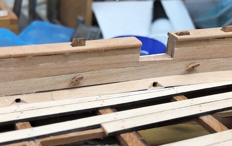
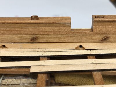
Now done and also I treated the deck with oil to get a feeling for the final appearance (you see very good the difference at the small spot close to the gunport where no oil is on the timber
installed cleats at the area near the bow
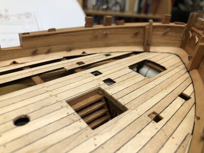
I decided to install all cleats before I install any other fittings on the deck - now I had much better access with my small hand drill (for the brass pins of the cleats)
Here I compared each location and the number of cleats as well as their purpose with the help of all available drawings, either CAF and also Jean Boudriot in order to define best
Many Thanks for the interest .....
several smaller parts and elements are done in the meantime
mastfoot at the stern

The shheves blocks are done with five wooden elements

the pully is runnung on an axis and is turning

additional "bitt" on top of the rails near stern

I made also some samller stiffeners between the vertical timbers at the top of the transom - not shown in the drawings, but I guess for structural reasons, they had some on the real ship

and also the cleats were started
on top you see the untouched cleats right out of the lasered sheet
at the bottom you see some cleats already preliminary sanded into form with also removing the laser char - a lot of work
due to the fact, that I plan to fuloly mast and rigg the model I thought, that it will be better to make in the center a pin, so later on the cleats will be more secured and better fixed - the brass rod has a diameter of only 0,5mm, so you get an impression of the size


To make life easier (and maybe also better results - a good alternative would be the finished cleats by @Dry-Dock Models & Parts

Pearwood Cleats
Dry - Dock Models & Parts is providing high quality ship model fittings and parts
 drydockmodelsandparts.com
Be aware, that in the kit only 30 small cleats are prepared - and as I counted all together you need 28 installed - so be very carefull and do not distroy too much during preparation and installation
Installed cleats - with this close up photo I realized, that there is still some glue spots to be removed and cleaned

Now done and also I treated the deck with oil to get a feeling for the final appearance (you see very good the difference at the small spot close to the gunport where no oil is on the timber

installed cleats at the area near the bow

I decided to install all cleats before I install any other fittings on the deck - now I had much better access with my small hand drill (for the brass pins of the cleats)
Here I compared each location and the number of cleats as well as their purpose with the help of all available drawings, either CAF and also Jean Boudriot in order to define best

Many Thanks for the interest .....
What a beautiful model, beautifully staged, applause, applause.
Step by step to finalize the stern area of the model
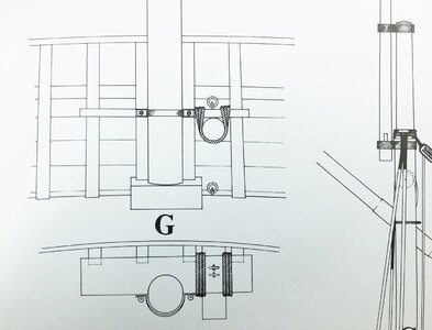
This is an excerpt of Jean Boudriots drawing showing the location of the mast and the fixing of the stiff boom, which passes the transom trough a hole
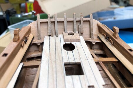
I decided that it is now the best time for drilling the hole trough the transom
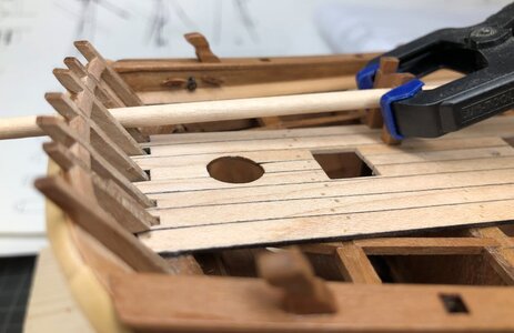
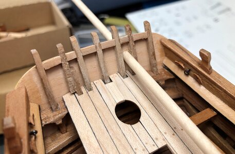
Only after final definition of the location of the hole it will be possible to define the height of the horizontal board against the mast is fixed (red arrow)
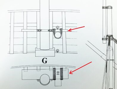
Many Thanks for your interest .... to be continued

This is an excerpt of Jean Boudriots drawing showing the location of the mast and the fixing of the stiff boom, which passes the transom trough a hole

I decided that it is now the best time for drilling the hole trough the transom


Only after final definition of the location of the hole it will be possible to define the height of the horizontal board against the mast is fixed (red arrow)

Many Thanks for your interest .... to be continued
What I want to highlight when other modelers are coming to this working step.
If you want to rigg (green arrow) the connection between the boom and the small board correctly, like it is shown in the drawing, please take care, that there is some space (red marked distance) between the board and the inside of the transom planking. You need this space (blue marked area) for the two slings of the ropes
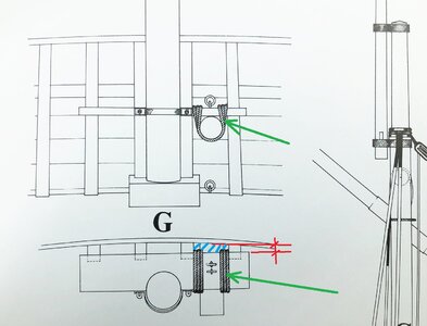
If you want to rigg (green arrow) the connection between the boom and the small board correctly, like it is shown in the drawing, please take care, that there is some space (red marked distance) between the board and the inside of the transom planking. You need this space (blue marked area) for the two slings of the ropes

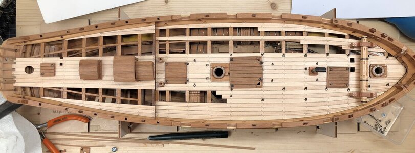
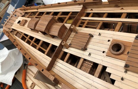
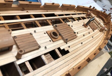
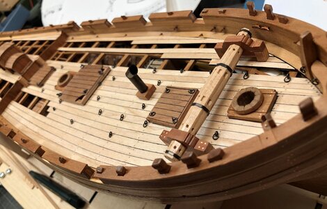
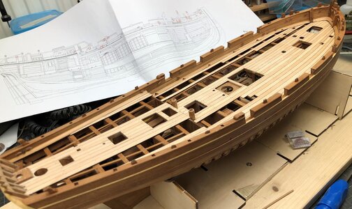
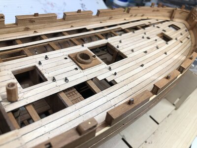
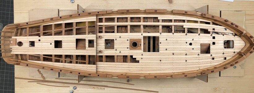
Not only the cleats are easier to be installed, before the rest of the deck fittings and houses are fixed on the decks - also the total and relatively big number of eyebolts or eyelets on the deck could be installed now
Also for this I used either the CAF drawings and also the given information by Jean Boudriot (partly there are differences) to define the correct location and numbers

As usual also in the top view, maybe partly as a reference for others
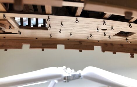
as a check, that no glue fixed the ring with the eyelet, I turned the model upside down - all rings are movable
Also for this I used either the CAF drawings and also the given information by Jean Boudriot (partly there are differences) to define the correct location and numbers


As usual also in the top view, maybe partly as a reference for others

as a check, that no glue fixed the ring with the eyelet, I turned the model upside down - all rings are movable

Accelerated progress ...
Beautiful, Uwe!
Beautiful, Uwe!


