-

Win a Free Custom Engraved Brass Coin!!!
As a way to introduce our brass coins to the community, we will raffle off a free coin during the month of August. Follow link ABOVE for instructions for entering.
-

PRE-ORDER SHIPS IN SCALE TODAY!
The beloved Ships in Scale Magazine is back and charting a new course for 2026!
Discover new skills, new techniques, and new inspirations in every issue.
NOTE THAT OUR FIRST ISSUE WILL BE JAN/FEB 2026
- Home
- Forums
- Ships of Scale Group Builds and Projects
- Le Coureur 1776 1:48 PoF Group Build
- Le Coureur 1776 1:48 Group Build Logs
You are using an out of date browser. It may not display this or other websites correctly.
You should upgrade or use an alternative browser.
You should upgrade or use an alternative browser.
LE COUREUR - french Lugger 1776 - POF kit from CAF in 1:48 by Uwe
Man Uwe, you are unstoppable, just great.
I just have 2 weeks vacation and Le Coureur is at my company. So I can only start again properly from the 16th of August. But my family is grateful that I have time for them now.
I just have 2 weeks vacation and Le Coureur is at my company. So I can only start again properly from the 16th of August.
I love these finishing details Uwe - and so artfully rendered. I love watching you work.
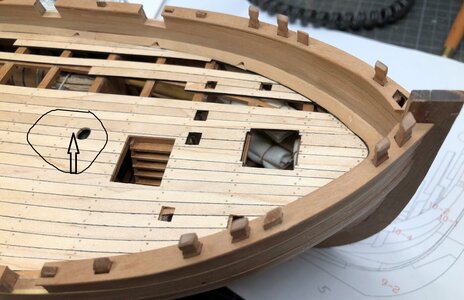
I have absolutely no knowledge about it but when building a ship (or anything else) I think there are mainly 3 considerations to balance: the functional aspect, the aesthetic aspect and the economic aspect. Personally I cannot think of any technical or functional differences whether the nails are placed diagonally one way or the other. From an economic point of view I’m sure there is no difference . Hence I would put all weight on the aesthetical aspect and make the port side a mirror of the starboard side, exactly as you have done. That said, this reasoning raises immediately another question in my mind: Isn’t the same perspective just as valid for the deck planking? Shouldn’t the nailing in the port half of the deck be a mirror of the starboard side?I have one question and maybe somebody knows the answer, or have some opinion.I did not find any information in my complete library, so ......
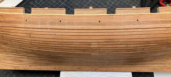
Oriantation of the nails in the cravel planked area
Either way, it is becoming a very beautiful model.
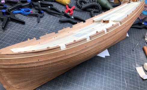
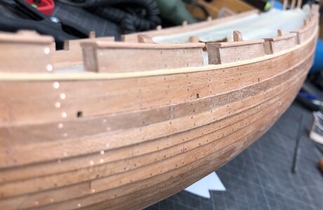
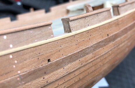
In the meantime I was able to install the rail elements of one side and sanded them in the area of the gunports
View attachment 248376
View attachment 248378
View attachment 248377
View attachment 248379
Today I hope to finish also the other side .... to be continued
Many Thanks for your interest in my build
Mega, really great job.
Just want to show with the manual sketches the order I installed the rails - the order is different to the information given by the manual, but for me personally this order worked better.
first off all I installed the outer planking - with this the top level of the rails was defined
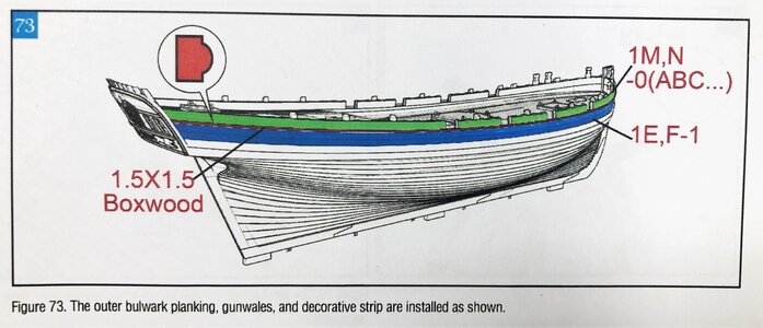
afterwards with knowing the top end I installed the inner planking (with 1,5*5mm), the waterway was installe already earlier together with the deck planking
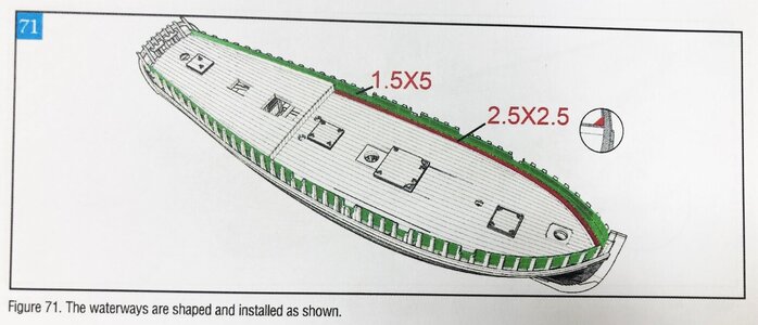
After sanding the top edges of the planking (inner and outer) I was able to install and adjust the top timbers of the rails
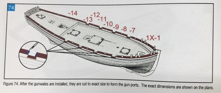
and the last activity was the installation of shortened top timbers into the notches which were precut into the top timber of the rails. ESpecially at the bow section there are so much toptimbers passing through the notches, I had my doubts that this would work following the order of the manual.
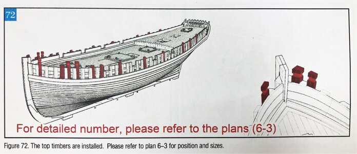
In the following post I will show the installation of these top timbers
first off all I installed the outer planking - with this the top level of the rails was defined

afterwards with knowing the top end I installed the inner planking (with 1,5*5mm), the waterway was installe already earlier together with the deck planking

After sanding the top edges of the planking (inner and outer) I was able to install and adjust the top timbers of the rails

and the last activity was the installation of shortened top timbers into the notches which were precut into the top timber of the rails. ESpecially at the bow section there are so much toptimbers passing through the notches, I had my doubts that this would work following the order of the manual.

In the following post I will show the installation of these top timbers
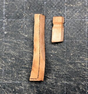
This is one pair of the top timbers, which are passing the notches in the top, on the left slightly sanded, on the right one prpared, which will be installed into the norch of the top
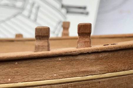
Two installed
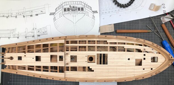
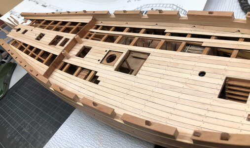
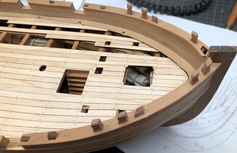
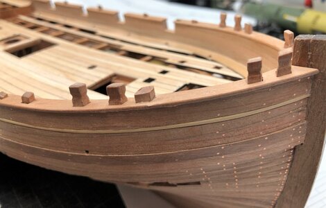
The last open notch (on the right directly at the bow) will be closed - here no toptimber will be installed, because the bowsprit will pass here over the rail
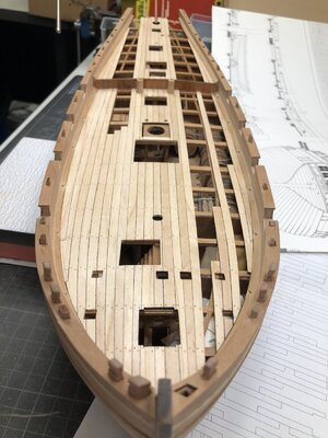
Many Thanks for your interest ..... to be continued .....

Two installed


The last open notch (on the right directly at the bow) will be closed - here no toptimber will be installed, because the bowsprit will pass here over the rail

Many Thanks for your interest ..... to be continued .....
Well prepared, absolutely great work.
The floor, with the deck is a different case. If you do the symmetry as you wrote, then the bolts on the central board of the deck will match. Therefore, on the deck, the bolts go from side to side in sequence. I hope I explained it clearly. Uwe, sorry for the off top.That said, this reasoning raises immediately another question in my mind: Isn’t the same perspective just as valid for the deck planking? Shouldn’t the nailing in the port half of the deck be a mirror of the starboard side?
The next part or small project in the project are the preparation of the two catheads at the bow
Here are as usual the sketches of the manual defining the elements necessary for the catheads
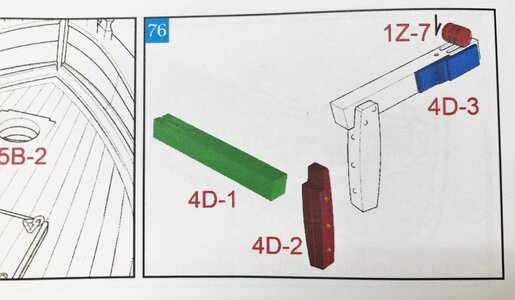
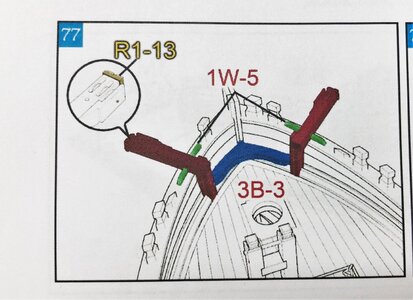
It is looking easy and the parts of the cathead in sheet 4D are looking very good -> so let us do it
But like mentioned before - it is a small project
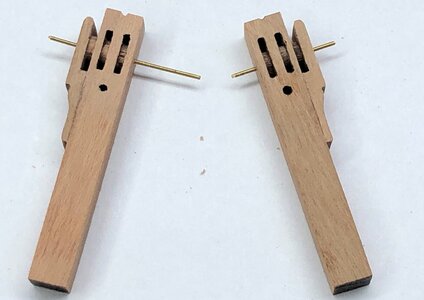
On the left side you see the parts of one cathead partly still with the laser char. On the small wooden roller or wheels i left partly the char, so that they are a little bit darker than the beam by itself. So you have a little bit more contrast.
I decided to drill a hole through the complete beam with 0,5mm, so I can put the wheels on an brass axis, so that they are able to rotate
On the right the second cathead with temporary installed wheels
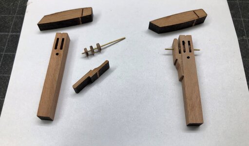
closer view on the beam
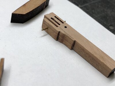
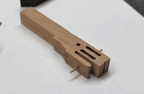
the wheels are rotating - I was thinking about sanding the wheels circumference concav, but they are really small and later on not really visible
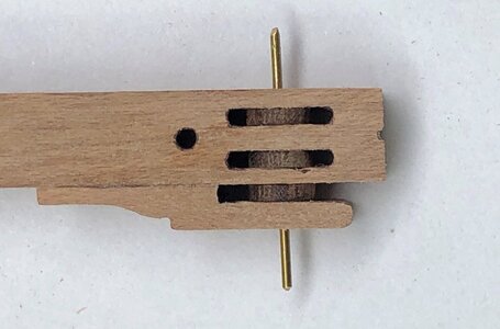
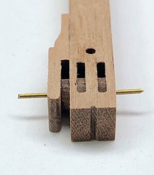
Both beams are now prepared
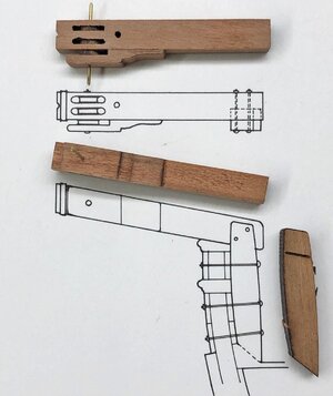
comparing with Jean Boudriot drawings of the planset of the Le Coureur
Still some thing to do ......
Here are as usual the sketches of the manual defining the elements necessary for the catheads


It is looking easy and the parts of the cathead in sheet 4D are looking very good -> so let us do it
But like mentioned before - it is a small project
On the left side you see the parts of one cathead partly still with the laser char. On the small wooden roller or wheels i left partly the char, so that they are a little bit darker than the beam by itself. So you have a little bit more contrast.
I decided to drill a hole through the complete beam with 0,5mm, so I can put the wheels on an brass axis, so that they are able to rotate
On the right the second cathead with temporary installed wheels

closer view on the beam


the wheels are rotating - I was thinking about sanding the wheels circumference concav, but they are really small and later on not really visible


Both beams are now prepared

comparing with Jean Boudriot drawings of the planset of the Le Coureur

Still some thing to do ......
I understand your point but I'm still in doubt how it should be. In the mean time I tried to do some research. Unfortunately I did not find anything convincing in writing but I did find quite a lot of pictures (both models and full size ships) where starboard and port side of the deck was mirrored. A few examples.The floor, with the deck is a different case. If you do the symmetry as you wrote, then the bolts on the central board of the deck will match. Therefore, on the deck, the bolts go from side to side in sequence. I hope I explained it clearly. Uwe, sorry for the off top.
Model:
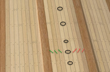 Real ship:
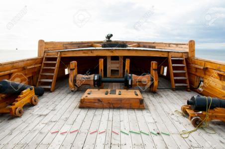
But I also fould a lot of pictures were it was not made that way. Thus I'm still in doubt what way is most appropriate
There are also contemporary models showing both ways of deck nailingI understand your point but I'm still in doubt how it should be. In the mean time I tried to do some research. Unfortunately I did not find anything convincing in writing but I did find quite a lot of pictures (both models and full size ships) where starboard and port side of the deck was mirrored. A few examples.
Model:
View attachment 249025Real ship:
View attachment 249023
But I also fould a lot of pictures were it was not made that way. Thus I'm still in doubt what way is most appropriate
The model in the model turned out very nice. It makes your mouth water to get the point yourself.The next part or small project in the project are the preparation of the two catheads at the bow
Here are as usual the sketches of the manual defining the elements necessary for the catheads
View attachment 249012 View attachment 249013
It is looking easy and the parts of the cathead in sheet 4D are looking very good -> so let us do it
But like mentioned before - it is a small project
On the left side you see the parts of one cathead partly still with the laser char. On the small wooden roller or wheels i left partly the char, so that they are a little bit darker than the beam by itself. So you have a little bit more contrast.
I decided to drill a hole through the complete beam with 0,5mm, so I can put the wheels on an brass axis, so that they are able to rotate
On the right the second cathead with temporary installed wheels
View attachment 249005
closer view on the beam
View attachment 249006
View attachment 249007
the wheels are rotating - I was thinking about sanding the wheels circumference concav, but they are really small and later on not really visible
View attachment 249008
View attachment 249009
Both beams are now prepared
View attachment 249010
comparing with Jean Boudriot drawings of the planset of the Le Coureur
View attachment 249011
Still some thing to do ......
- Joined
- Apr 20, 2020
- Messages
- 6,257
- Points
- 738

wonderful work, well doneThe next part or small project in the project are the preparation of the two catheads at the bow
Here are as usual the sketches of the manual defining the elements necessary for the catheads
View attachment 249012 View attachment 249013
It is looking easy and the parts of the cathead in sheet 4D are looking very good -> so let us do it
But like mentioned before - it is a small project
On the left side you see the parts of one cathead partly still with the laser char. On the small wooden roller or wheels i left partly the char, so that they are a little bit darker than the beam by itself. So you have a little bit more contrast.
I decided to drill a hole through the complete beam with 0,5mm, so I can put the wheels on an brass axis, so that they are able to rotate
On the right the second cathead with temporary installed wheels
View attachment 249005
closer view on the beam
View attachment 249006
View attachment 249007
the wheels are rotating - I was thinking about sanding the wheels circumference concav, but they are really small and later on not really visible
View attachment 249008
View attachment 249009
Both beams are now prepared
View attachment 249010
comparing with Jean Boudriot drawings of the planset of the Le Coureur
View attachment 249011
Still some thing to do ......
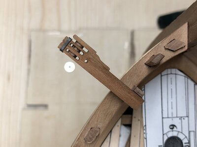
Continueing with post #893 and the work on the catheads
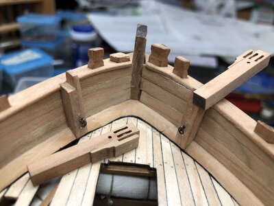
tem,porary installed, and the rail and arm not adjusted - in order to get a feeling and checking where and what has to be done
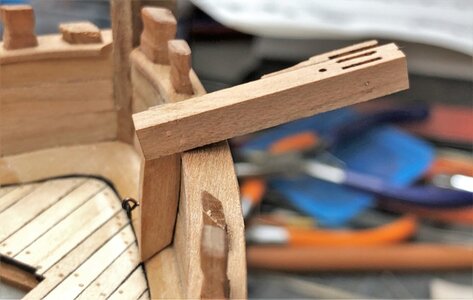
The vertical part at the rails is finished and fixed with "three bolts" and adjusted also with an eyelet
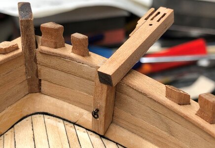
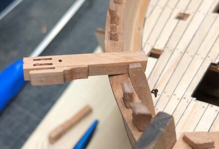
the three "bolts have to be added also at the nailing of the outside planking
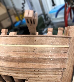
also the second one
stepy by step I am coming closer to the end result
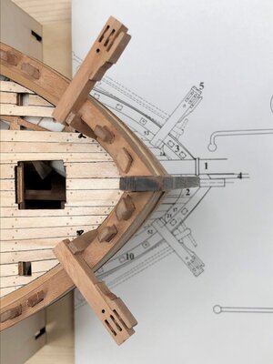
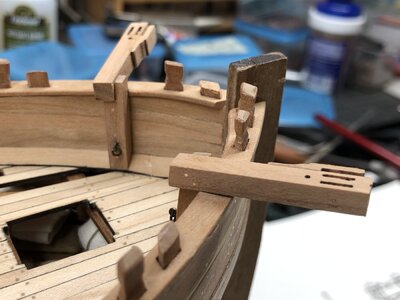
the top of the rails have to be also adjusted slightly, so that the cathead beam is laying on the rails - in order to fix it temporary I added an (later) unvisible nail
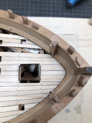
now tha cathead front and end has also the correct angle - vertical towards the sea-level
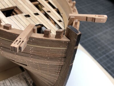
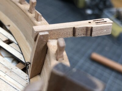
Now only the metal reinforcement band at the last end is missing
tem,porary installed, and the rail and arm not adjusted - in order to get a feeling and checking where and what has to be done

The vertical part at the rails is finished and fixed with "three bolts" and adjusted also with an eyelet


the three "bolts have to be added also at the nailing of the outside planking

also the second one

stepy by step I am coming closer to the end result


the top of the rails have to be also adjusted slightly, so that the cathead beam is laying on the rails - in order to fix it temporary I added an (later) unvisible nail

now tha cathead front and end has also the correct angle - vertical towards the sea-level


Now only the metal reinforcement band at the last end is missing
- Joined
- Apr 20, 2020
- Messages
- 6,257
- Points
- 738

The fit between the parts and the body of the ship-deck, looks great and beautifulContinueing with post #893 and the work on the catheads
tem,porary installed, and the rail and arm not adjusted - in order to get a feeling and checking where and what has to be done
View attachment 249214
The vertical part at the rails is finished and fixed with "three bolts" and adjusted also with an eyelet
View attachment 249215
View attachment 249216
the three "bolts have to be added also at the nailing of the outside planking
View attachment 249217
also the second one
View attachment 249218
stepy by step I am coming closer to the end result
View attachment 249219
View attachment 249220
the top of the rails have to be also adjusted slightly, so that the cathead beam is laying on the rails - in order to fix it temporary I added an (later) unvisible nail
View attachment 249223
now tha cathead front and end has also the correct angle - vertical towards the sea-level
View attachment 249221
View attachment 249222
Now only the metal reinforcement band at the last end is missing The fit between the parts and the body of the ship-deck, looks great and beautiful
The project of the catheads is going further
You can find the small "iron" bands on the photo etched brass sheet of the kit
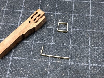
I used first time the bender from Roman alias @RC Model which is working extremely good - I am not a specialist for these works, but such a device is helping a lot to get real right and sharp angles into a brass part
and I need some more practice in the handling, but time (and brass parts) will help
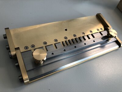
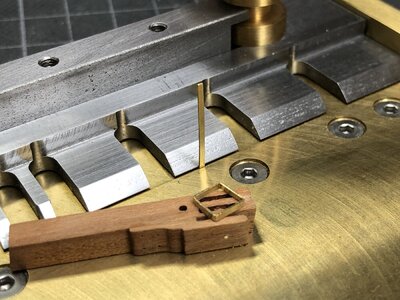

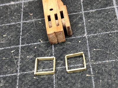
It is only 5mm * 5mm
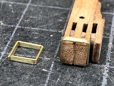
after blackening or better blueening with Balistol
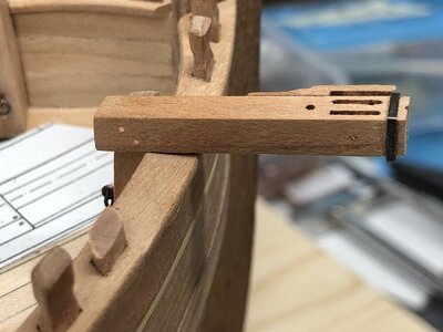
I am happy with the result
What is coming next? - OH - I have still not finalized the stern -> another challenge to solve ....
Many Thanks for your kind interest
To be continued ......
You can find the small "iron" bands on the photo etched brass sheet of the kit

I used first time the bender from Roman alias @RC Model which is working extremely good - I am not a specialist for these works, but such a device is helping a lot to get real right and sharp angles into a brass part
and I need some more practice in the handling, but time (and brass parts) will help


It is only 5mm * 5mm

after blackening or better blueening with Balistol

I am happy with the result

What is coming next? - OH - I have still not finalized the stern -> another challenge to solve ....
Many Thanks for your kind interest
To be continued ......


