LE COUREUR - french Lugger 1776 - POF kit from CAF in 1:48 by Uwe

Many Thanks for all your comments, kind words and all the likes received - highly appreciated

The deck planking works are going on

like on the other deck I prepared some sheets of planks glued together, once more with the "painted" caulking in the joints
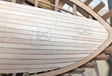
On this photo you can see already two sheets, on the middle one with 9 planks, I marked already the center lines of the beams as preparations for the treenailing and the appr. areas of the deck openings for the hatches and and mast partners
IMG-6549.jpg

the sheets are already adjusted to fit in between the waterways
IMG-6550.jpg

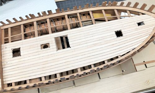
the openings are already precut. Such works are much easier to make, before the planks are glued and fixed on top of the beams - important is only not to forget any of them (so do not forget the mast-partners, the bitts, the chimney of the oven and the pumps)
IMG-6551.jpg

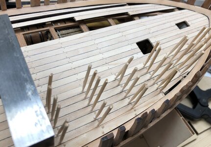
ongoing treenailing with the same technique like on the other deck described some days before
the first 50% of nails
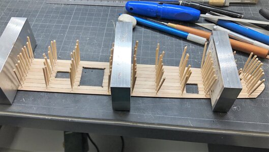
IMG-6555.jpg

and the rest of the nails - with this sequence of installing my fingers have enough space to hold the toothpicks during "nailing"
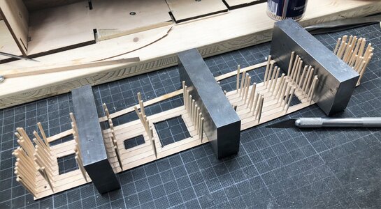
IMG-6560.jpg

one sheet the treenailing is done (without sanding and scraping) - the other sheets is still waiting for the nails
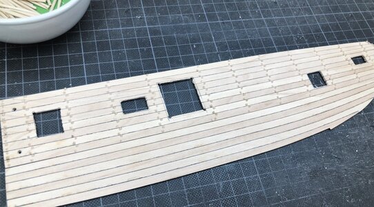
IMG-6561.jpg

Many Thanks for your all interest .... to be continued - the next post will show the first guns on the deck :cool: ;) :cool:
 
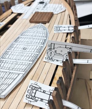
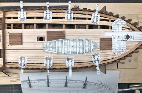
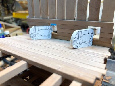
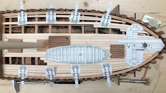
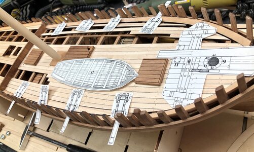
Today I can show you the first time some guns on the deck - OK, not the build guns but "paper"-guns
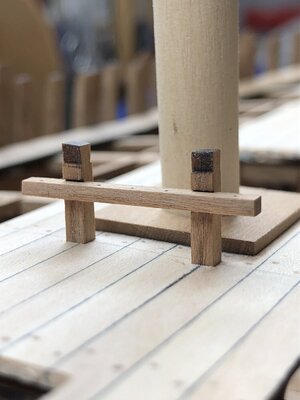
IMG-6564.jpg

IMG-6563.jpg

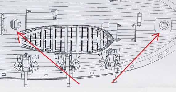
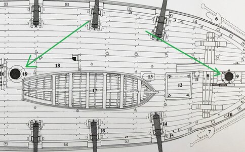
I made this to check the more or less final location of the wheels of the guns, but also the boat, spill etc.
So I know more in detail, whcih deck planking will be necessary and which planks could be eventually "deleted" to keep the visbility down into the hold
Such paper tests are helping me often to make decisions
 
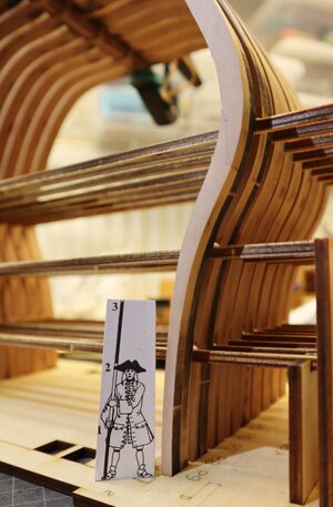
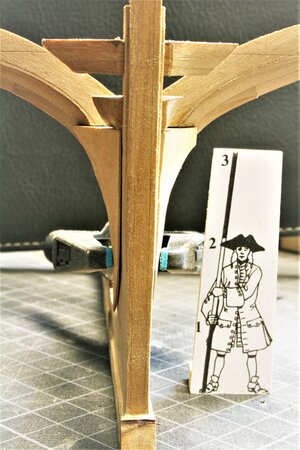
What i have learned from my project is that´s very helpful to check some geometrys with a man or a canon in the scale. Better doublcheck before than remove the parts because they are wrong.
I have a small supervisor in scale 1:48 checking often my work on the different models
Easy done - a copy of a Boudriot drawing

IMG_4159.JPG IMG_31591.jpg

IMG_47961.jpg

such a dummy gun is very helpful to get a feeling for the correct gunport size and height
67b.jpg

For the Le Coureur I have to make new gun dummies, due to the fact, that the armament was much much smaller - she had only 3pdr. guns
 
Progress on the nailing was ongoing and for the moment finished

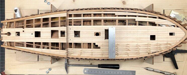
The last "sheet" with planks is located on the beams only for drying and is not fixed yet
IMG-6581.jpg

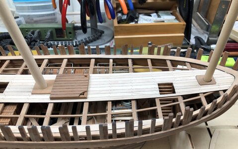
in the meantime you can get a feeling, how and where I will install the deck planking
IMG-6580.jpg

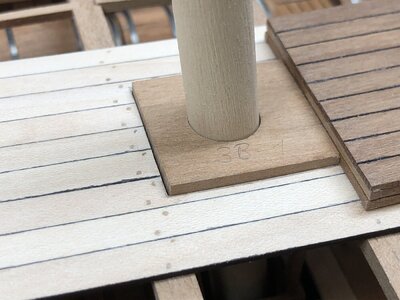
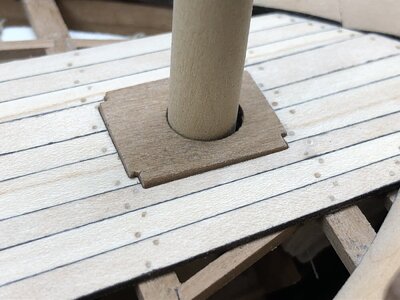
The mast partner of main mast is already installed (here I have to make the wedges)
IMG-6584.jpg

you will recognize, that the deck is still only dry fitted - There are several openings to prepare (for bitts, mast partners, pumps etc.) which I want to make before the planking are fixed
IMG-6585.jpg

Many Thanks for interest ..... to be continued ....

Just a short remark:
The paper dummies I use are from the Boudriot planset, maybe you realized already, that the windlass is different compared to the kit design - so stay tuned, in some days I will show the difference and what I will make
 
Progress on the nailing was ongoing and for the moment finished

The last "sheet" with planks is located on the beams only for drying and is not fixed yet
View attachment 239521

in the meantime you can get a feeling, how and where I will install the deck planking
View attachment 239520

The mast partner of main mast is already installed (here I have to make the wedges)
View attachment 239522

you will recognize, that the deck is still only dry fitted - There are several openings to prepare (for bitts, mast partners, pumps etc.) which I want to make before the planking are fixed
View attachment 239523

Many Thanks for interest ..... to be continued ....

Just a short remark:
The paper dummies I use are from the Boudriot planset, maybe you realized already, that the windlass is different compared to the kit design - so stay tuned, in some days I will show the difference and what I will make
Looks very nice.
But ....... are you changing to the "SOS Build Logs from Paper / Cardstock" ? ;)
Regards, Peter
 
More openings to do in the deck planking ..... The Le Coureur is a small ship, but seems like she has the same number of slots like a 74 gunner ;)

Main mast partners
IMG-6587.jpg

foremast partners
IMG-6586.jpg

IMG-6588.jpg

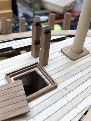
Than we have the bitts for fixing the bowsprit
IMG-6589.jpg

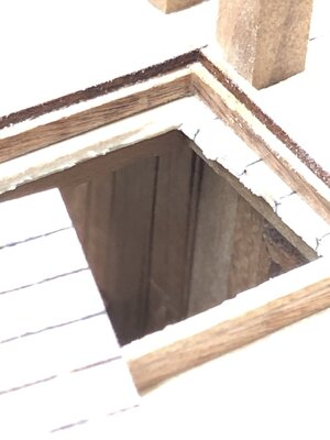
they are visible also under deck via the ladder hatch (sorry for the bad quality photo)
IMG-6590.jpg

The bitts near the main mast
IMG-6591.jpg

These bitts are sitting half on the beam
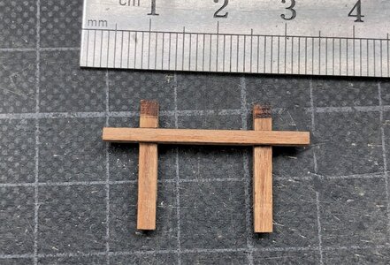
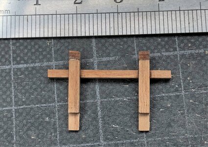
IMG-6594.jpg

IMG-6592.jpg

IMG-6593.jpg

Missing are still the slots for the anchor spill and the pumps (hope I did not forget one....)
 
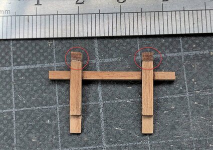
Greetings, Mon Amie. While looking at the nice bits provided in the kit, I came across the question. I see, that the cut is slightly angled inside on both bits. Is this by design or simply optical illusion on the photo?

IMG-6593.jpg

Thank you,
 
Greetings, Mon Amie. While looking at the nice bits provided in the kit, I came across the question. I see, that the cut is slightly angled inside on both bits. Is this by design or simply optical illusion on the photo?

View attachment 240072

Thank you,
Hallo Jim,
it is not a optical illusion - the laser cut of this parts are in fact not so accurate, but it is here aboslutely no problem, due to the fact, that you have to sand the head of the bitts into a 3 dimensional formed head .....
The parts are very small, the vertical timber is 2mm wide, so we are talking about a difference of maybe 0,3mm .....
 
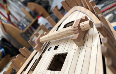
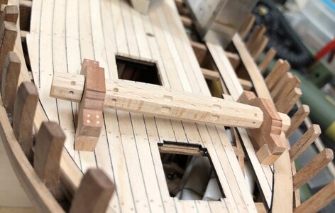
The next main small project inside the ship project will be the anchor spill or windlass.

General:

Due to the fact, that the Le Coureur was a small ship, there was no space or technical possibilities of a vertical capstan, so such ships has an horizontal spill or windlass.
Capstans had the big advantage, that a continous rotation was possible, because the seaman could walk around the capstan.
The big disadvantage of the horizontal spills was the fact, that it could turned only for a small angle, than they had to fix the spill drum, and afterwards the seamen were able to put the crank into another hole of the spill, with once more turning only for a small angle........ so lifting an anchor took much more time with such a spill........

On the model:

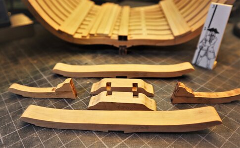
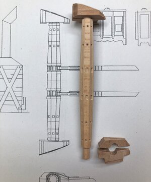
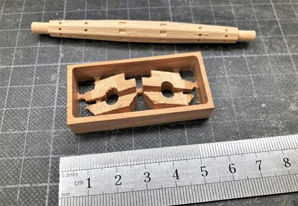
These are the parts provided within the kit - the drum and four cnc cut elements which will bethe base of the windlass drum.

IMG-6595.jpg


Please be aware:
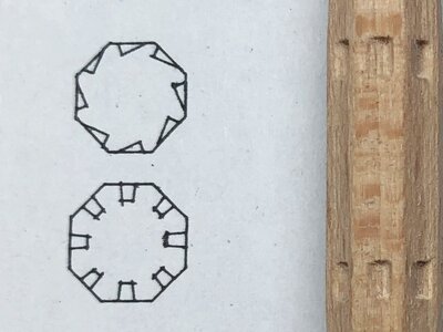
the drum has all together six rows of notches -> on the left and the right each time two rows of square notches for the windlass handles / cranks (lower cross section )
and
in in the center two rows of rectangle notches for the "brakes" (upper cross section)
-> and now IMPORTANT: these notches are asymetric cut, in such a way, that the brake-timbers are fitting well and hinder the turning of the drum.

IMG-6597a.jpg

So if you install the drum of the windlass please check twice the correct alignment of the drum !!!!


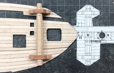
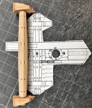
Here you can see the four elements of the windlass provided in the kit on top of the CAF drawing
IMG-6599.jpg

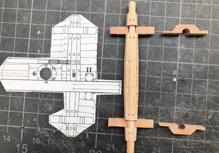
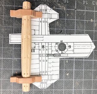
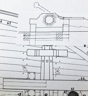
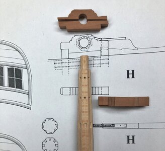
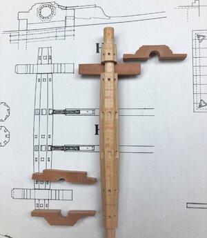
and here we compare the "kit-windlass" with the drawing of the Jean Boudriot planset. Boudriot interpreted it in a different way and showed the drum based on two bases, each between the first and second row for the handles - with this arrangement the total length of the drum (and width on the deck) is shorter!
IMG-6596.jpg

Before I made a final decision, I made some samples for the "Boudriot-bases" in scratch - good enough to go further in this direction
IMG-6598.jpg

It worked well with the bases so i sanded down the drum, so that the notch was just wide enough that the base elements are fitting
IMG-6601.jpg


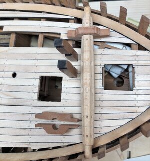
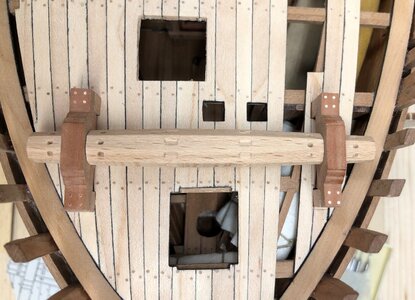
Here you can see the (by in moment 50%) adjusted windlass on the correct place on the deck
IMG-6600.jpg

both sides prepared - still with the original extension of the axis for the bases
IMG-6602.jpg

and now with closed bases and shortened drum - now the windlass is 99% the Boudriot version
IMG-6603.jpg

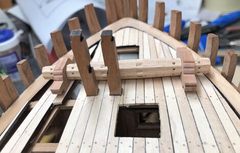
and now back of the windlass on top of the planking at the correct pace - missing here are the four vertical pillars on which the windlass is fixed towards the deck beams
IMG-6604.jpg

My change on the windlass is not a "must" or a "should be done" - it is purely a different way compared to the kit design - here I followed the Boudriot drawings

Many Thanks for your interest ..... to be continued .....
 
Many Thanks for your kind words and the likes received - highly appreciated

This is a great solution to stick with Boudriot's drawing. Works much better than CAF variant. Simply great job. Did you use pear wood for the bearings?

Hallo Adi,
It is not pear, but Elsbeere (german name), Sorbus torminalis, with common names wild service tree, chequers, and checker tree, which has a similar grain but often some more touch into red. I like this timber the most for scratch building

 
Some more photos working on the windlass

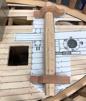
Here you can see, where the bearings of the windlass have to be installed
crossed with some pencil lines are the two deck beams, so the vertical pillars are bolted horizontal through both beams
IMG-6606.jpg

So approximately here would be the correct place
IMG-6605.jpg

IMG-6607.jpg

IMG-6608.jpg

Due to the fact, that the fixing construction of the windlass bearings will be completely hidden by the planking, I decided, that I will not make them

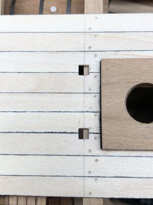
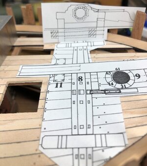
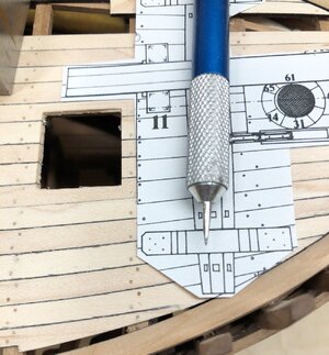
Using the paper template and a scriber I "copied" the location of the four vertical pillars into the planking (you can see each time 5 holes in the paper)
IMG-6609.jpg

and cut out the slotsIMG-6610.jpg

Many Thanks for your interest .... to be continued ....
 
Today I will show some more works on the windlass - not really big progress, but I took some time to cut out these slots as accurate as for me possible.
Very helpful for this work is the fact, that the deck planking is still not fixed on the beams, so all these works can be done directly on the working table
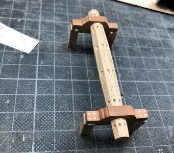
pillars fixed with glue and with some oversize in the cross section - I made also some bolts (0,5mm)
IMG-6611.jpg

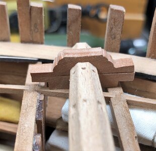
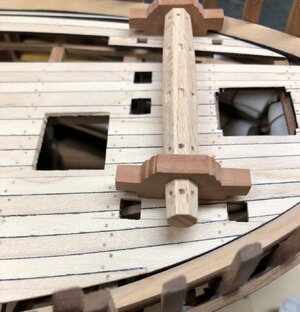
Now the pillars of the bearings are sitting in slots on top of (better next to) the beams
IMG-6612.jpg

IMG-6613.jpg

IMG-6614.jpg

here you can see the windlass compared with the Boudriot drawing
IMG-6615.jpg

Step by step I am coming closer to the status, when I am able to fix the deck planking on top of the beams ......
to be continued ..... many thanks for your interest
 
With several days watching the european football (socker) championship on TV I was yesterday evening the first time back in my workshop.
Germany lost against England (Sch... :eek: AlienSpeechless:mad:) - so afterwards (I am German) I can fully concentrate on my modeling - Many Thanks to the English

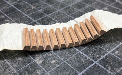
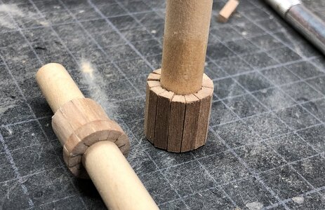
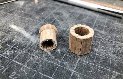
I started with the preparation of the wedges of the mast partners. This detail is not part in the kit, here the mast is sitting directly against the partners, so I will make them from scratch.

First of all a short comparison of the drawings

IMG-4675a.jpg

IMG-4675b2.jpg

I forgot to make a photo of the longitudinal cross section, but this I will add in short time

I am using some pear strip, cut into 1,5cm long segments and sanded them accordingly
IMG-6619.jpg

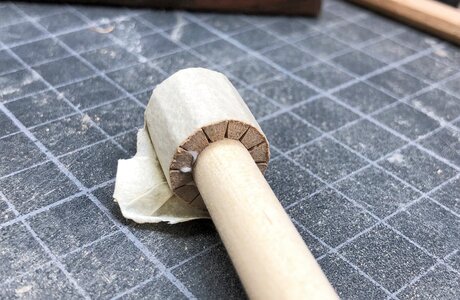
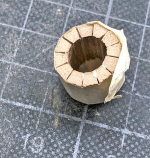
The photo before is showing the wedges stick to a adhesive band , now with some glue between the segments and fixed them around the mast-"dummy"
IMG-6620.jpg

IMG-6622.jpg

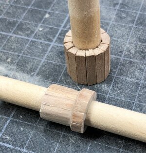
The second also wedges also prepared, and the first already was brought to the correct form - still a lot of sanding and adjustment necessary

IMG-6623.jpg

IMG-6624.jpg

IMG-6625.jpg
 
Back
Top