Le Mercure ANCRE Plans

Planking Section C:

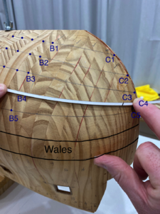
If you refer to the photo you now have a series of dots from the very stern of the hull all the way to the front of Section B. These dots are shown as blue dots in my photo. You also have dots at the very bow - shown in my photo as C1, C2, C3, C4 and C5. (Please disregard the pencil lines in my photo as these would not be there at this stage).

Now, using my flexible piece of plastic and trying to preserve proportionality between the widths of the bands I simply join B1 to C1, B2 to C2, B3 to C3 and so on and each time mark this with a pencil. Each line must then be carefully checked from all angles to ensure it runs smoothly. If it doesn't you need to make adjustments.

You can reference the plans here for additional key points or details if you need to. For example, you will notice in my image the section B4 - C4 - C5 - B5 has 3 planks tapering down to only 1 plank at the very bow. This is shown on the plans and has been preserved on my hull.

You now need to extend the solid line all the way to the stern of the model. Join all dots for each band from section B back to the very stern using the same flexible plastic. Again, the line must be smooth all the way from bow to stern. This might mean you have to fudge a dot here or there. If you have high quality and reliable plans and pay attention to accuracy with measurements it will pay off royally at this time.

One key point to ensure is that the band widths don't go from narrow to wider and then narrower again as you move back towards the stern. If a band does this then the band needs to be adjusted slightly to esnure a constant narrowing as you move sternwards.

Now it is a case of planking each band separately ensuring you stay within the lines for each band. I haven't started this process yet but I will post photos as I do.

I am now experimenting with caulking options for the hull planking.

Also, I will use Swiss pear for the hull planking.
IMG_1033.png
 
keep up with the updates Antonio
. Question . After making those frames and fastening them together into the solid hull how exactly did you remove that extra material to bring the hull down to its lines ?
thanks Tony
 
Hi Anton/Antonio,
Which do you prefer sir? I must say, I shake my head at the precision of your work. It would be impossible to dispute your methods, (or Dr. Mike's "technologies") as the final results speak for themselves. The only time I've ever seen such precision is in my own work, (cough, cough, not my modelling), as a structural engineer. Do you happen to be an engineer sir? Regardless, if you're not, many engineers would envy your precision.

Thanks for sharing your "technologies" and methods. They have been logged in my knowledge base to be applied at a later date. You've saved me much time.
Cheers,
Ken
 
@tonphil1960: This is a good question. Material needs to be removed from one side of the frame only and this is done with a variety of electric tools and then finally by sanding very carefully. I use red lines in Crayon on the frame to mark the "do not sand past this point of the frame" and then sand until these lines are reached. Perhaps (please give me some time) I'll dig up older photos of my hull construction and post them so you can see exactly what I do. Photos will make this process much clearer than the written word.

@Hoss6262: Thank you for your kind comments. Antonio is my name but I am not fussed what you call me :-)
I am very familiar with engineering work as a consequence of completing 2 years of electronic engineering at University. However, I didn't finish this degree and instead ended up finishing a degree in mathematics. However, I work in a completely different field now and have forgotten almost everything I learned :-). If I understand correctly you are you a structural engineer?

I will be happy to keep posting my progress. Whilst there is no question Dr Mike got me on this path and I do use a lot of his techniques, I have been modifying processes to accommodate my own preferences. For example, for my deck caulking he uses paper and I use paint because I prefer a subtle thinner line and I find paper rips and is trickier to deal with.

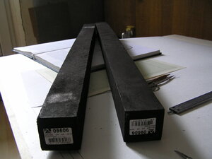
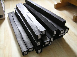
Dr Mike is sending me some Black hornbeam from Russia. The quality is absolutely superb - consistently jet black like nothing he has ever seen before. I will use this for the wales and other black components.

The hull planking is the next step and this is not straight forward as we are dealing with a surface that is not flat like a deck (excluding the minor camber) but a surface that curves in 3 directions. The edges of the planks will need to be angled (so they are not 90 degrees to their face) in order to ensure that adjacent planks butt up perfectly against each other to avoid gaps between planks.
 
Hi Antonio,
Yes, I am a Structural Engineer. You would think that knowledge would translate seamlessly to scale modelling, but sometimes the languages have barriers. hahah. Once again, thank you for sharing your knowledge.
Cheers,
Ken
 
Hmmm, I have received interesting news from Dr Mike which I now recall him discussing with me but had forgotten!

When I was in Russia I recall taking the bus with Dr Mike and Alex Dobrenko to visit another Russian ship modeller who lived outside of St Petersburg. This modeller built his models "admiralty style" and the hull was almost entirely built from Swiss Pear. The modeller was commenting that his joins would be "perfect" at certain times of the year but then have gaps between them at other times.

Dr Mike commented to me that Pear (for use on large surface areas such as hull construction and planking) was a problem because it has a very strong tendency to "breath" - that is expand and contract as it absorbs moisture from the air. So, if you plank a hull at one point in the year you might find small gaps opening up between joins at other times of the year. The same goes for hull planking apparently - even if you are attaching the full surface area of the Pear plank to another surface (such as is the case with my model).

Whilst this might not be an issue for many modellers (and rightly so), if you are trying to preserve gapless joins throughout the year it is apparently a serious problem. So much so, that Dr Mike only uses pear for deck details and smaller areas.

This has thrown my plans in to chaos as I was planning to use Pear under the waterline.

So I put a question to you all - what woods do you all like to use under the waterline?
Can anyone recommend any darker brown woods (similar in colour to Pear)?
I don't like to use stains as I feel they always look like a stain. I would much prefer a natural finish.
I haven't tried dyes but have been told they can look very natural. Does anyone have any experience?

Dr Mike has made an interesting and very aggressive suggestion which I will share with you shortly. I am keen to hear some of your ideas first before hitting you with his dramatic suggestion.
 
Dr Mike's suggestion certainly sounds radical and as such most interesting. On my Haarlem build, I used "good ole" walnut (from the Netherlands) which worked very well with no gaps opening up at all. I mention this because we have had extreme humidity during summer in China (Nantong - Jiangsu Province) this year - so much so that I actually had problems with mildew forming on the decks.
 
G'day Antonio, do you think it could be because of the extremely cold winters that they have, and the central heating, none of the models I have have opened up at all, though I did rig one model with synthetic cord and in the summer the rigging was tight and in the winter it was slack, just food for thought,

best regards John,
 
In central Europe most of the scratch build models are built from pear or Elsbeere, and I did not realized this extreme behaviour.
I know from Russia, that they often have district heating systems, and to regulate the temperature in the rooms, they often open the windows.
Often the rooms are overheated - could be a reason, that the models suffer from the higher differences and changes in temperature and humidity.
 
@Uwek: Yes, I strongly suspect the factors you have suggested would contribute to this issue.

Our French colleagues who use Pear have experienced and reported the same issues with it.
In Australia we use air conditioning in summer and heating in winter and I suspect (without performing my own experiment) that this would result in the same issue.

Unfortunately avoiding fluctuations in humidity is not possible. (I can imagine asking my wife to turn off the air conditioning at home when the temperature is 45C because my model won't like it... ;) )

Dr Mike has suggested I use Black Hornbeam from the top of the main wales all the way down to the keel. I should explain that to an extent he sees models as "artistic creations" and modellers as "artists" who need to have some artistic license and creativity - particularly with wood and colour use. The model itself must be beautiful. This might seem contradictory given his fine attention to historical detail and accuracy.

I welcome your thoughts on this suggestion and will keep mine private for the moment...
 
Black the entire hull ? I guess it would look interesting but Id think if the Mercure didn't have a black hull Id not go that route. I Read somewhere on one of your threads Antonio (not sure if it was on this site ) that Dr Mike is now using Birch Plywood for his hulls,,? Any ideas where I can find some info on it ?
Thanks Tony
 
Black only from the main wales down and hundreds of blackened metal nails with rounded heads that would only be very subtly visible from close range.
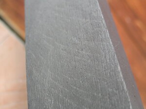
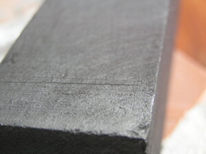
Black hornbeam is extremely uniform in colour and polishes superbly. It bends easier than Ebony and is not as hard on tools. The latest batch (see photos) has no grey or white flecks through it - it is extremely uniformly black. In fact, Dr Mike has told me he has never seen quality this high before.
Above the main wales lighter woods would be used.
It would certainly be making a statement and wouldn't be to everyone's taste.
When I get a second I am going to take a photo of my hull and use photoshop to see what it might look like.

I think this is what Dr Mike means when he talks about an artistic statement and the need to deviate from tradition or historical accuracy if you feel like it. He believes (I think) that it doesn't necessarily have to be a colour replica of the real ship. We already do this to some degree (some times with out realising it) when we build our models. As has been stated on other threads, the decks on our models are very light which is not historically accurate. We deviate from historical facts to try and make our models look "beautiful" rather than historically accurate.

P1010002.JPGP1010003.JPGP1010004.JPGP1010001.JPG
 
Hi Tony - my apologies, I didn't answer your last question.

Yes, Dr Mike's hull manufacturing technique has changed since the videos but relies on very similar principles. He has not published any information about it that I am aware of (and I also use the Russian forum). What specifically would you like to know?
 
oh just how its changed if at all with using the plywood for the shell. I guess not much its just a different material. Ill search the Russian forum too maybe ill find some info. That is some beautiful wood the Hornbeam I guess it would look good with the contrasting woods, there's nothing wrong with artistic license is right.
 
Hi Tony,
Yes correct - Dr Mike uses plywood and has been for some time. He draws (on to paper) the profile of each plywood frame using the waterline and side elevations and then cuts the frame from this shape. This, in itself, is a common way to create frames. However, the key difference is that this is done as a solid hull without spaces between consecutive frames. Whilst this is a lot more work it gives a continuous surface for final planking and a very solid hull. It also becomes a very heavy hull!
 
There is no more stable a base. The way it’s connected with dowels and screws makes it bulletproof. Yes a lot of work building a ship scratch or frames is a big job to begin with. You must have really absorbed Dr Mike and Alex’s teachings because for a first model you’re doing fantastic work. I’ve watched the vids quite a few times and I’ll keep watching them until I learn all I can.
 
Hello all,
Please accept my apologies for my absence. I was waiting for a shipment of pear and black hornbeam from my Russian colleagues and unfortunately it has not arrived. So while I wait for this shipment (to plank my hull) I have decided to build the cannon carriages with some of the pear I already have. As such, I will take a diversion from hull planking to cannon carriages.

I start this process by breaking down the cannon carriage in to its individual components and I manufacture each of these: a base, 2 x sides, 2 x wheel axels, wheels and various other small wooden and metallic parts.

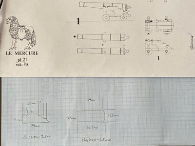
In the first image I have very carefully measured the dimensions of the cannon carriage from the plans and re-drawn the key individual components (at this stage only the base and sides) on 1mm graph paper. As I build the cannon carriage I will consider the other smaller components. For the time being however, I will build these parts only and this will largely be done with a milling machine.

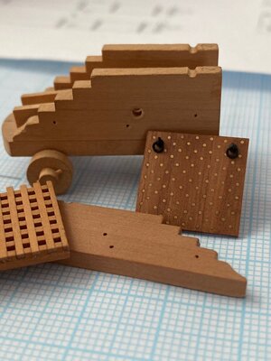
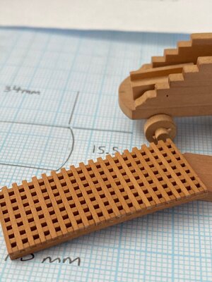
For your interest I attach a photo of an almost completed cannon carriage (minus the metallic components), a gun port lid (with quite a few brass nails) and also part of a hatch. I will discuss the manufacture of these parts in the future.

I'll post again shortly....

IMG_1464.jpg

IMG_1466.jpg

IMG_1467.jpg
 
Last edited by a moderator:
@Brian: Thank you but these pieces are old and scuffed up. I found the cannon carriage in my son's bedroom on the floor (he took it from my workshop ;)) and the gunport lid also has some faults that have annoyed me.

Either way, I'll use the same principles to re-build these pieces.

I managed to spend a few hours in my workshop today with the aim of building the cannon carriage sides.

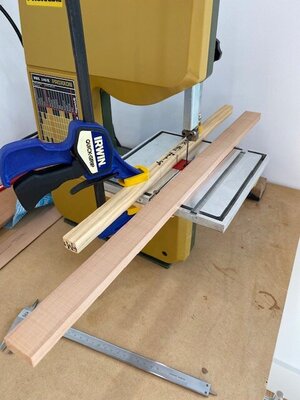
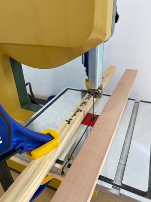
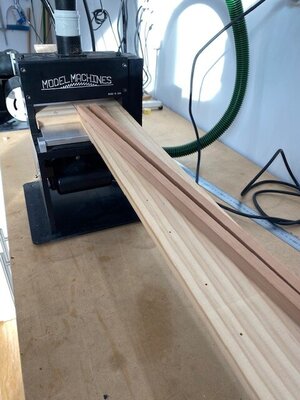
I use a bandsaw to cut down my larger piece of pear and as you can see from my photos this can be achieved really nicely if you attach a guide to the bandsaw table as I have done with a piece of pine. Then once the pear has been cut down, I put this through the thicknesser to thickness it down to the required dimensions (in my case 11mm exactly). As you can see I have modified the Byrnes sander to extend the table by inserting a long flat piece of pine to eliminate sniping. This is essential as I thickness almost every single piece of wood I use and they are often longer pieces.

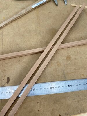
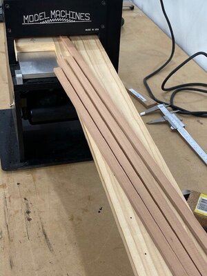
Then the pear (that has the correct height of 11mm) goes through the bandsaw again and is thicknessed in the other direction to achieve a thickness of exactly 2.5mm. Thus, I end us with lengths that are 11mm wide and 2.5mm thick - the exact dimensions needed for the carriage sides.

This takes a bit longer than using a table saw but eliminates any possibility of the pear burning and gives a very smooth, exact and clean finish. Also the bandsaw has a thinner blade than the circular saw so I find I get less material loss and it cuts thicker pieces of pear very comfortably.

If I have time tomorrow I will start the process of setting up my milling machine to cut the profile of the carriage sides.

IMG_1475.jpgIMG_1476.jpgIMG_1477.jpgIMG_1481.jpgIMG_1483.jpgIMG_1485.jpg
 
Back
Top