Great work Antonio. yes there's going to be alot of spiling. The 6 bands are just how it worked for you or did you use some reference for that number of bands ? I love those heavy solid hulls. A great stout platform to perform the rest of the work on.
-

Win a Free Custom Engraved Brass Coin!!!
As a way to introduce our brass coins to the community, we will raffle off a free coin during the month of August. Follow link ABOVE for instructions for entering.
-

PRE-ORDER SHIPS IN SCALE TODAY!
The beloved Ships in Scale Magazine is back and charting a new course for 2026!
Discover new skills, new techniques, and new inspirations in every issue.
NOTE THAT OUR FIRST ISSUE WILL BE JAN/FEB 2026
You are using an out of date browser. It may not display this or other websites correctly.
You should upgrade or use an alternative browser.
You should upgrade or use an alternative browser.
Le Mercure ANCRE Plans
- Thread starter LeMercure
- Start date
- Watchers 38
-
- Tags
- ancre le mercure
Thank you.
There is no question that the solid hull makes a wonderful surface for the final planking. However, creating the solid hull in the first place is more time consuming and difficult than the traditional plank of frame approach. Also, the model starts to get very heavy.
Whilst my hull is solid I do have frames which you will see numbered from 1-56.
As for the 6 bands and the process of drawing lines my logic is as follows:
> I start by marking (in pencil) the exact position of the bottom wales at each and every frame. This information is taken directly from the plans. These dots are joined with a smooth line.
> From the plans and at midships there are 23 planks from the bottom of the wales to the keel. (Note: The wales themselves are an additional 3 planks and are being handled separately).
> Given there are 23 planks, I created 5 bands of 4 planks and one of 3 planks. (I think 4 planks per band is a good number but there are no hard and fast rules).
> I measure the required width of each plank. At midships it is relatively easy to the extent that I simply divide the width measured from the keel to the bottom of the wales (177mm) by 23 planks to get a width of plank of 7.69mm at that point. If you then multiply that width per plank by 4 (or 3) you get the thickness of the band at that frame. I mark this with a pencil dot.
> I repeat this process through midships towards both the bow and stern. However, as you get closer to the bow things get a little tricky.
> OK here is the key point: At the point where the bow meets the keel I used the plans (specifically the plans showing the hull planking) as a guide as to where each band should finish (that is how far up the keel it should finish) and mark this with a dot. Starting at this dot I used a flexible piece of plastic to join the dots along the length of the hull with a nice smooth line checked from all angles. My wife kindly helped me hold the flexible piece of plastic as you need many hands to do this.
> My aim is to try and ensure the thickness of the bands remain as consistent as possible along the length of the hull - including at the bow and the stern.
> This does involve trial and error
> Once the bands have been drawn on the hull, I then start planking each band (as a project in itself!) starting from the wales to the keel. This is yet to come.
It is crucial to spend time drawing these lines and finishing them before any planks are actually attached.
The planking bands have now been carefully drawn on both sides of the hull. Their positions have calculated very carefully and will guide the exact positions of the planking. Each band will be planked separately starting from the wales and moving towards the keel.
The lines must be absolutely smooth and free from kinks or sudden bends. Also, you must ensure that the bands do not go from wide to narrow and then wider again.
I will explain my techniques in creating these bands in more detail shortly.
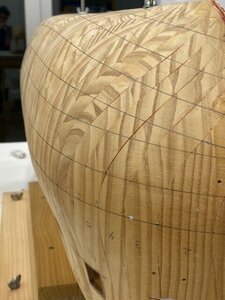
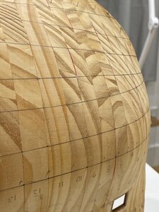
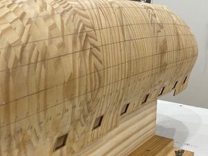
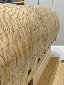
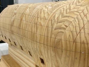
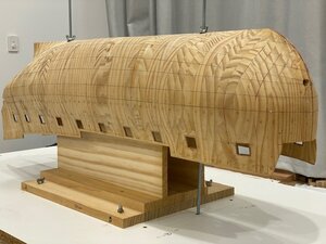
The lines must be absolutely smooth and free from kinks or sudden bends. Also, you must ensure that the bands do not go from wide to narrow and then wider again.
I will explain my techniques in creating these bands in more detail shortly.


Last edited by a moderator:
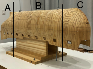
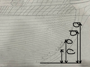
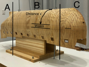
To create the bands I crudely I think of the hull in 3 parts - A, B and C (please refer to photo) although there is no definitive ending or stating points for sections A, B or C.
I start by deciding I will have 4 planks per band (aside from one band which will have 3 planks only because this includes 2 drop planks). This is just my preference - you could justifiably have 3 or 5 planks per band.
Section A determines the termination of the planking at the stern and section C the commencement of the planking bands, whilst section B is mid-ships and is treated slightly differently (I will explain why shortly).
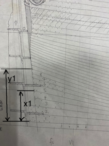
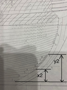
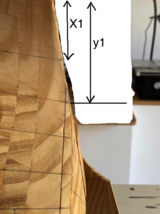
I start by thinking about the end points of the planking at the bow (C) and stern (A) and exactly where these bands should be located - that is how far up the keel. I want to determine the exact position of the tops of the bands. I read this directly from the plans and measure the distance "a" and "b" at the keel and similarly at the bow (refer to 2 photos). These key points are marked very carefully with a dot on the ship's hull. So now, I have marked the tops of each of the bands at the bow and stern.
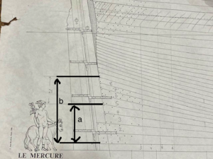


Last edited by a moderator:
Watching very closely Antonio
Hi all,
I am scratch building Le Mercure from ANCRE plans.
I post some photos of my main deck. This is built off of the model and inserted later which makes working with the deck much easier. I still have further scraping and sanding of the deck - this is only rough at this stage. The centre strip (which will remain raised by about 1mm) is only temporarily held in place with toothpicks (which are not visible). Again, the ability to detach parts as needed (and not applying glue until the very end) makes working with these items far easier.
My main deck is built in 3 separate parts but when joined appears as one.
You will also see nails which I make with a syringe and Pear wood. I have several thousand of these which I will insert in to the deck in the coming days.View attachment 156064View attachment 156065View attachment 156066View attachment 156067View attachment 156068View attachment 156069View attachment 156070View attachment 156071
Hallo my friend, @LeMercure ,
we wish you all the BEST and a HAPPY BIRTHDAY

Happy Birthday Antonio!! Many more successful days to come! 

Happy Birthday !
Antonio,
why not start a you-tube forum for your build log ? Then we can see how Dr Mike's protege is progressing.
why not start a you-tube forum for your build log ? Then we can see how Dr Mike's protege is progressing.
Happy Birthday Antonio!
This is a very good idea.
I support you, Brian.
This is a very good idea.
I support you, Brian.
Thank you all for the birthday wishes!
@Brian077: Interesting idea! Let me give it some thought.
I must apologise, I wrote my last message in haste after a strong G&T and whilst I am sure many of you understood what I was trying to explain, I could have explained the process better with detailed photos.
Please let me start again from the very beginning and I will explain the full process over the next week or so.
Imagine my hull finished and sanded and ready to have the lines drawn on it for planking. Imagine there are no lines nor wales drawn on the hull. We are now trying to establish the hull planking. This is my process:
#1 Draw the position of the top of the main wales on both sides of the hull
The top of the main wales delineate the top of the hull planking and so this is my starting point. Planking above the main wales is handled later. We are concerned with planking below the main wales at this time.
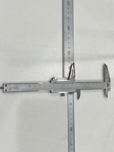
To do this I start by making my own device which consists of a vernier calliper with two rulers glued on to it. This allows the calliper to slide in and out so that I can adjust the size of the opening as would normally be the case. The purpose of the rulers will become obvious shortly. This is an essential device to make! Please refer to device.jpg
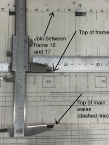
Then for each and every join in two frames on my model starting from 1-2 and working to the end (there are 56 frames in total) I measure directly from the plans the position from the top of the frames to the top of the main wales. I do this by placing the calliper directly on the plans with the top jaw aligned with the top of the frames and the bottom jaw aligned with the top of the main wales (the dashed line) at the junction between those 2 frames. Refer to MeasuringVerticalDistance.jpg
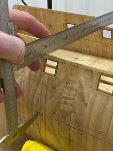
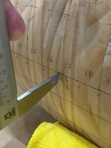
I then lock the calliper to fix this distance and transfer this vertical distance directly to the model by sitting the vernier calliper across the model and specifically the junction of frames in question (in this case 16 and 17) and allowing the bottom jaw of the calliper to touch the model. By applying a small amount of pressure I can mark (or dent) the frames very slightly at the exact position. I then use a pencil to place a dot in this position. Please see Wales1.jpg and Wales2.jpg
Repeat the process on the other side of the hull at the same junction of frames.
When this is done go back to the plans and adjust the calliper mouth size based on the distance between the top of frames 17 and 18 and the top of the main wales. Repeat the process for all frames on the model.
*** The accuracy of this process is highly dependent on the top of the frames of the model being absolutely correct in respect to the plans and is a separate process not described here. I ensure this is the case and then I can confidently use the top of the frames as a reliable reference point for further measurements on the model. ***
The bottom point of the main wales for each and every junction of the frames can be easily measured at every frame by simply using a piece of paper, laying it on the plans at that frame junction and marking the top of the wales with one dot and the bottom of the wales with another dot. Move this paper to the corresponding frame on the model placing the top dot on the dot you drew earlier marking the top of the wales and then mark the bottom edge of the wales directly from the paper. Repeat this process for every frame.
I then use a thin and flexible piece of plastic to join the dots on the top and bottom of the wales forming a solid line. This line must be perfectly smooth so it may be that you have to pass just above or below a dot or two to form the line.
So we now have a smooth hull with the main wales (top and bottom edges) drawn on it. If you have been careful they will be perfectly symmetrical on both sides and absolutely consistent with the plans.
Now to drawing the planking bands....
Last edited by a moderator:
#2 Determine how many planking bands will be used and mark their end points at bow and stern
Planking bands simply allow me to break up the planking process into smaller bits. Each band will consist of individual planks. Once all the planking bands have been drawn on the model I will plank each in turn starting from the wales and working towards the keel. However, I must spend considerable time locating these bands perfectly on the model to prevent any problems when I start planking.
I start by counting how many strakes (rows of planks) there are by reading this directly from the plans. Counting at the thickest part of the hull there are 23 strakes from the bottom edge of the main wales to the keel (the main wales are excluded from this calculation). At the bow there are only 21 strakes (the plans show that 3 planks will merge in to 1). There are no stealers on the plans so there are 23 strakes at the stern.
So I have decided that since 3 strakes will merge in to 1 at the bow I will treat these are one band. This leaves 20 strakes. I like the idea of 4 strakes per band meaning there will be 5 bands of 4 strakes and one band of 3 strakes.
I am now interested in drawing a series of dots as I did for the main wales along the length of the hull specifically to delineate the tops of each of these bands. This is the skill - to determine where these dots should go so the line is smooth and realistic. It is not technically difficult but does require some thinking and considerations to be made in advance.
I start at the extremities - that is the bow and stern and use the plans to guide the lowest 2 bands (at the keel). The reason I focus on the bottom band is because you will notice on the plans these planks are slightly wider and fan out and I want to preserve this detail as accurately as possible.
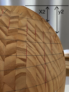
Please now refer to the photos (and excuse the crude photoshopped arrows ). I measure directly from the plans the distances x1 and y1 at the stern and the distances x2 and y2 at the bow that represent the extremities of the bottom two planking bands (each of these bands will contain 4 planks). These distances x1, x2 , y1 and y2 are then transferred to the model with a dot at the bow and the stern. You can repeat this process with the remaining bands at the bow and stern.
Now we have formed the points at which the bands begin and end although we may need to adjust these slightly down the track.
Now comes the part of marking the tops of the bands along the entire length of the hull (not just the end points). This will be left for another post...
Planking bands simply allow me to break up the planking process into smaller bits. Each band will consist of individual planks. Once all the planking bands have been drawn on the model I will plank each in turn starting from the wales and working towards the keel. However, I must spend considerable time locating these bands perfectly on the model to prevent any problems when I start planking.
I start by counting how many strakes (rows of planks) there are by reading this directly from the plans. Counting at the thickest part of the hull there are 23 strakes from the bottom edge of the main wales to the keel (the main wales are excluded from this calculation). At the bow there are only 21 strakes (the plans show that 3 planks will merge in to 1). There are no stealers on the plans so there are 23 strakes at the stern.
So I have decided that since 3 strakes will merge in to 1 at the bow I will treat these are one band. This leaves 20 strakes. I like the idea of 4 strakes per band meaning there will be 5 bands of 4 strakes and one band of 3 strakes.
I am now interested in drawing a series of dots as I did for the main wales along the length of the hull specifically to delineate the tops of each of these bands. This is the skill - to determine where these dots should go so the line is smooth and realistic. It is not technically difficult but does require some thinking and considerations to be made in advance.
I start at the extremities - that is the bow and stern and use the plans to guide the lowest 2 bands (at the keel). The reason I focus on the bottom band is because you will notice on the plans these planks are slightly wider and fan out and I want to preserve this detail as accurately as possible.
Please now refer to the photos (and excuse the crude photoshopped arrows
Now we have formed the points at which the bands begin and end although we may need to adjust these slightly down the track.
Now comes the part of marking the tops of the bands along the entire length of the hull (not just the end points). This will be left for another post...


A wealth of the valuable information, Antonio! Many thanks for sharing.
@Jimsky - I am glad this is helpful!
Please let me continue.
We now have the starting and end points for the planking bands only drawn at the very stern and the very bow. There are no points plotted along the length of the hull. Please remember that we have drawn the upper and lower edge of the main wales along the entire hull by joining the dots with a a pencil line and a thin piece of flexible plastic. This line must be checked to ensure it is absolutely smooth from all angles before proceeding as it will become a reference line moving forward. You may need to erase parts of this line and re-draw it to ensure it is perfectly smooth.
We will now endeavour to draw the planking bands along the entire hull.
The attached image shows how I break up the hull planking in to 3 distinct sections: A, B and C.
Strictly there is no definitive point where each section starts and ends. Section C deals with the bending of the bands at the very bow and I treat this as a section in itself because I will not follow the rules I apply for sections A and B. Strictly, on my particular model, I don't actually need a section A as there are no stealers and the rules and logic I apply in Section A will be the same as Section B. I have included Section A because if I did have stealers I would do things in this section A slightly differently.
Starting at the thickest part of the hull (which is a particular junction of two frames) I measure the distance x very carefully (please refer to HullSection.jpg). This is the distance from the keel to the bottom of the main wales. At this frame junction count the number of hull planks that will intersect the distance x which is read directly from the plans.
My measurements were:
Distance x = 177mm
Number of planks = 23
Since I want to ensure that all 23 planks have an equal width at this point, I divide the value of x (177mm) by 23 giving a plank width of 7.7mm.
Now it is easy: one of my bands has 4 planks so the width of this band (at this frame junction) will be 7.7 x 4 = 30.8mm
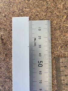
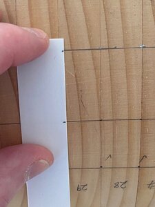
Transfer this measurement of 30.8 by marking two dots on to a piece of paper (I actually use a thin piece of plastic) and use this to measure up from the bottom of the main wales (which remember have already been drawn in full) and place a dot on to the hull exactly 30.8mm from the bottom of the main wales. (Please refer to images MarkPoints.jpg and TransfertoHull.jpg)
Now simply repeat this process for the remaining bands at the point (frame junction) along the hull bearing in mind that one of the bands has only 3 planks and will therefore only be 3 x 7.7mm = 23mm wide. Since most of my bands are 4 planks wide I can use the same piece of paper with the 2 dots to repeat the process quickly at this same frame junction.
You need to repeat this process (measuring the value of x and re-calculating the width of the planks and then the bands) at every frame on the model for the entirety of Section B and (in my case) Section A because there are no stealers. *** You could do this every 2 or even 3 frames saving time but I like the accuracy of doing it at every frame ***
As you move backwards or forward along the hull the value of x will change. In my case the number of planks is always 23 until I get to the very bow (Section C) which I will discuss later.
You will now have a series of dots that delineate the planking bands from the very stern all the way to the intersection of bands B and C. Because (as I said earlier) the intersection of sections B and C do not have a definitive point I stop at the point where the bow starts curving in quite dramatically.
I will discuss the planking bands in section C shortly.


