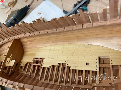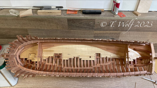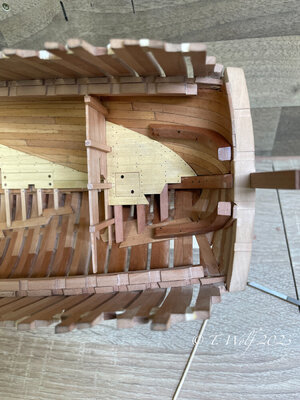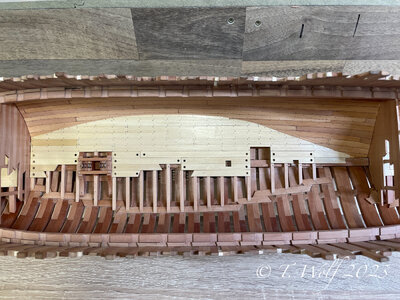
LE ROCHEFORT - Harbour yacht from 1787 1:36 by Tobias (Monograph by ANCRE)

Hi Tobias, your dovetail beam ends sent me poking around trying to learn more about this practice. As far as you know was this just a thing on French vessels? Thank you for your patience with my occasional questions...
A good question.
Hi Paul and Stephan, I will look into it but it could well be that it is something typically French. I know it from La Palme and various other French ships.
 
Lovely color and a great job across the boards! Thumbsup Question: Does CLOU act as the blackening solution as well? On one image I saw a brass part and then after you have treated it with CLOU it becomes black. I love the 'ironing' effect whatever solution you are using. It is not jet black it is iron blue!
 
Lovely color and a great job across the boards! Thumbsup Question: Does CLOU act as the blackening solution as well? On one image I saw a brass part and then after you have treated it with CLOU it becomes black. I love the 'ironing' effect whatever solution you are using. It is not jet black it is iron blue!

Hello Jim, thank you very much my friend.
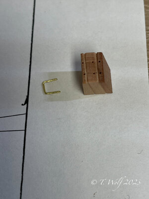
To your question, no the Clou does not blacken, what you saw was the reflection of the LED lamp. For blackening brass I use the product Nerofor from Ballistol, it has the advantage of not bleeding into the wood.

IMG_1276.jpeg
 
@dockattner @Tobias
About the dovetails on Dutch ships.
On the beams of the orlopdeck I can say yes.
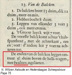
zwaluwstaarten.jpg

On page 75 it says "balk-wagers, met swaluen ingelaeten" In correct Dutch of this time. "Balkwegers, met zwaluwstaart verbindingen ingelaten" That means in English the beams got dovetails. (Bagger, i need to make them too! :rolleyes: )
Only the beams of the lower deck. The decks above don't have these. They don't have to carry a lot of load, like the guns says Witsen. I only have doubt about this, because the bigger ships with more guns on the upper decks. Witsen was talking about the pinas, it could be that a 2-decker does have dovetails also on the beams of the next deck.

And Paul, if a Dutch ship got them, the English want the too ROTF
 
Very good work,
did you bend the beams, or did you cut them out?
BTW: I think, that the british shipwrights did not use usually the dovetails joints
The other function, I did discovered of the dovetails, is to hold the ships sides together. So the side don't move outwards. No joints?

Hello Uwe, regarding your question, I cut the curved deck beams out of a board.

Now about the dovetails, I couldn't find anything about them in the plans of Naiad, Euraylus or Speedwell. Probably something French and Dutch.
 
The other function, I did discovered of the dovetails, is to hold the ships sides together. So the side don't move outwards. No joints?
Yes - you can reduce or even delete the need of laying knees - like the british had
The laying knees connected the beam with the braces
 
IMG_7198.jpeg

IMG_7199.jpeg

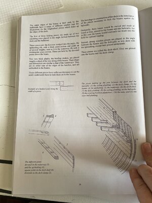
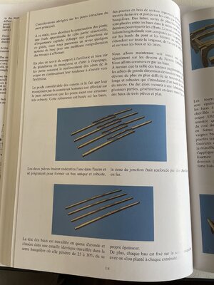
Abbreviated considerations for the bridge (main bridge structure). In this phase, we approach the construction of bridges. An in-depth examination of this important structural part is beyond the scope of this guide, but we will review some basic concepts to better understand the work to be done. The decks not only provide artillery support and, of course, manoeuvring platforms and shelter for the crew, but also reinforce the sides of the hull by counteracting the tendency to open outwards. The considerable weight of the guns and the fact that they are handled by many men on the bridge require the bridges to be very robust. This robustness is based on leases,

wooden beams with a large cross-section that are laid across the ship and supported on the sides by the boathouses. To distribute the forces, battens, thick planks, are laid between the rents in the same direction as the rents. The reinforcement and longitudinal bonding is completed by the gutters at the edges of the deck and the coamings in the centre, which extend along the entire length from front to back and over all the battens and slats. We will now see all these pieces individually in Fermín Urtizberea's drawings. We start with leases. As the size of the ships increased and large trees became rarer, it became increasingly difficult to find long, stable timbers that extended from one side of the ship to the other. We then had to resort to making them in several pieces, generally in two, but there were also hire contracts for three or more pieces.

The two parts were interlocked to form a single and robust structure with the connection area reinforced with iron dowels.

The head of the mouldings is dovetailed and fits into an identical recess in the balustrade greenhouse, where it penetrates 25 to 30 % of its own thickness. In addition, each beam is attached to the beam clamp with a nail hammered into each end.
IMG_7200.jpeg

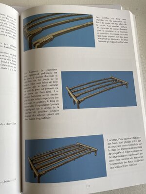
At the ends of the leases and on the sides of the hull are wooden arches pegged down. These curves support the dovetail notches for the gutter and gutter panelling, the other notches we see on the leases are for the coamings and buttresses that support the slats.

The gutter linings are also notched into the interlocking mouldings and dowelled to the sides of the fuselage. They are made so that the inside edge of the bridge side is bevelled or semi-circular. The Breton rails are then attached to the top of the gutter supports along the wall. These thick boards are attached to the top of the gutter panelling at the bottom of the openings, providing a strong longitudinal connection.

The louvres, which are smaller in cross-section than the rivets, are placed between them with their ends resting on the edge of the gutter supports at each edge. They rest on buttresses, the latter also having the task of maintaining the separation of the leases and avoiding their tendency to lie.
IMG_7201.jpeg

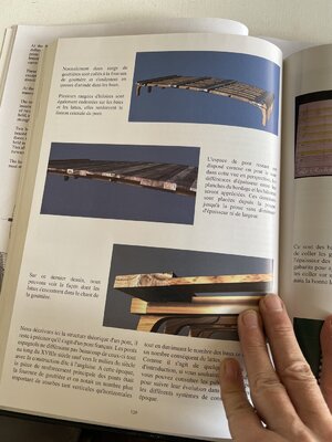
Normally, two rows of guttering are glued to the guttering underlay and fitted into the dovetails of the tenancies. Several rows of coamings are also serrated on the beams and slats; they reinforce the central connection of the bridge.

The remaining deck space is arranged as shown in this perspective view. The differences in thickness between the planking boards and the coamings are clearly recognisable. The latter are placed from the stern to the bow without any reduction in thickness or width.

In this last drawing we can see how the slats fit into the edge of the gutter. We describe here the theoretical structure of a bridge, it remains to be clarified that it is a French bridge. The Spanish pon hardly differed from these throughout the 18th century, except towards the middle of the century with the so-called English construction method. At that time, the main reinforcing part of the bridges was the gutter panelling, and we noticed a greater number of curves, both vertical and horizontal.

reduce Are arches without rger. At the same time, the number of leases is reduced, resulting in a significant number of slats. As these are just a few introductory notes, if you want to delve deeper into the subject, you can consult specialised publications to follow their evolution over time by tracing the different building systems of each era.


Source: Sorolla Modelisme D' Arsenal

I hope the translation is good I had to have it translated from French to English by Dr Google

And here is Gerard's explanation at Le Rochefort.
IMG_7197.jpeg

IMG_7202.jpeg
 
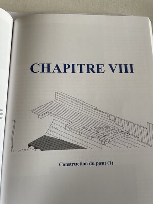
Translation from the accompanying book by Le Rochefort:


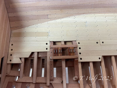
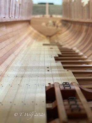
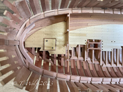
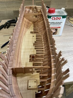
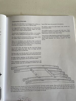
Construction of the deck The deck of Le Rochefort is not designed for artillery and is therefore simpler than that of battleships. It is supported by 20 beams, which are not supported by additional timbers (deck beams, mouldings, etc.), as used on ships with cannons, for example. The deck has a longitudinal curve or steep curve along its entire length, with an additional transverse curve or camber. Due to the shear, the ends of the deck became higher, while the camber curves upwards over the deck. These two curvatures, in addition to their mechanical function of strengthening the structure, allow the removal of water caused by rain or heavy seas by channelling it through the scuppers in the bulwarks. As we have seen, the beams are the crossbars that also support the deck. They also curve upwards and follow the curvature of the deck. We have also seen that the ends of the deck rest on the hooks, into which they are partially hooked with dovetail joints. To create openings for the hatches, the long beams must be replaced by several short beams. These openings consist of two longitudinal pieces, the spacers, the ends of which are embedded in notches cut into the surfaces of the beams in front of and behind the hatches. The spacers support the short beams with notches cut with dovetail joints. There are two smaller hatches at each end of the deck. Their placement is identical in relation to the beams, but short beams are not laid on either side of them. There are three other openings in the deck: the mast partner and the holes for the two pumps. Their construction is largely identical: two spacers coupled with fillers.

Partial view of the deck structure showing the beams with their various notches. The ones at the ends are dovetailed, one for fastening to the deck clamps and the other for inserting the longitudinal beams. One of the spacers for the hatch is on the right, its partner is outlined on the left to show the notches in the front of the beams. Also on the right are two short beams fitted into the spacer, which are also shown in the partner on the left.

The opening for the mast in the deck (the mast partner) is placed between two beams. It consists of two strong spacers (a), the ends of which are embedded in the beam surfaces, and two filler blocks (b). These parts are machined to form a tubular opening that is slightly angled backwards and follows the inclination of the mast. Four square chocks are attached to the corners.
 
Hello everyone,
many thanks to all of you who have liked so diligently over the last few weeks and provided a lot of positive energy with your comments. As I announced in a post some time ago, I would like to finish the construction phase (interior work). This means that Le Rochefort will now go on a well-deserved autumn/winter holiday for a few weeks and I would like to devote myself to La Palme again. I would be very happy to meet you there again, for more new conversations and a lively exchange. Our friend @shota70 has also already started work on the sister ship L'Amarante, which makes me personally very happy and the keel will soon be laid.

Of course, I won't neglect the group construction and will be on hand with help and advice if necessary.

IMG_1279.jpeg
 
Hello everyone,
many thanks to all of you who have liked so diligently over the last few weeks and provided a lot of positive energy with your comments. As I announced in a post some time ago, I would like to finish the construction phase (interior work). This means that Le Rochefort will now go on a well-deserved autumn/winter holiday for a few weeks and I would like to devote myself to La Palme again. I would be very happy to meet you there again, for more new conversations and a lively exchange. Our friend @shota70 has also already started work on the sister ship L'Amarante, which makes me personally very happy and the keel will soon be laid.

Of course, I won't neglect the group construction and will be on hand with help and advice if necessary.

View attachment 405562
Tobias my dear friend
I would love to continue to follow your impressive work on the blog of La Palme
 
Back
Top