Adi many thanks to you too, much appreciated.Hallo Tobias, very cleanly processed, makes an absolutely perfect impression, I like it very much.
-

Win a Free Custom Engraved Brass Coin!!!
As a way to introduce our brass coins to the community, we will raffle off a free coin during the month of August. Follow link ABOVE for instructions for entering.
-

PRE-ORDER SHIPS IN SCALE TODAY!
The beloved Ships in Scale Magazine is back and charting a new course for 2026!
Discover new skills, new techniques, and new inspirations in every issue.
NOTE THAT OUR FIRST ISSUE WILL BE JAN/FEB 2026
You are using an out of date browser. It may not display this or other websites correctly.
You should upgrade or use an alternative browser.
You should upgrade or use an alternative browser.
LE ROCHEFORT - Harbour yacht from 1787 1:36 by Tobias (Monograph by ANCRE)
- Thread starter Tobias
- Start date
- Watchers 71
-
- Tags
- ancre group build le rochefort
Perfect clean work. I know well I wont approach that !
As usual Tobias was correct. The angle vise from Micro-Mark is way too big and is being returned. I still working on a Rube Goldberg solution. To be continued…Thanks Tobias. I was looking at sine plates as well. Or possibly making one. Anyway, I’ll see if the angle vise works and decide from there.
Hi all, in Splitter's contribution it was about the construction of the frames and about the request of Uwe to make if necessary a pictorial instruction/explanation to it. I wanted to do this on Monday evening for you, but during the day the Corona virus has brought me more and more to my knees. As soon as I am healthy again I will do this. You can also like to look at my construction protocol of the La Palme there I have already described once.
Post #107
Post in thread 'POF La Palme (L'Amarante) Corvette 1744 1:36 (Ancre Monograph) by Tobias'
https://shipsofscale.com/sosforums/...36-ancre-monograph-by-tobias.9295/post-244538
Post #107
Post in thread 'POF La Palme (L'Amarante) Corvette 1744 1:36 (Ancre Monograph) by Tobias'
https://shipsofscale.com/sosforums/...36-ancre-monograph-by-tobias.9295/post-244538
I bought this cheap one from eBay. It’s smaller than the big one I was using and if I take the orange blocks off it’s lower. I’ll rig some angle plate for this one I hope. We’re only milling wood. A rigid set up really isn’t required.As usual Tobias was correct. The angle vise from Micro-Mark is way too big and is being returned. I still working on a Rube Goldberg solution. To be continued…
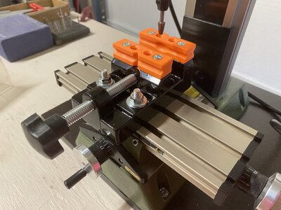
Take care of your health Tobias ! Good luck and a fast recovery.
- Joined
- Dec 3, 2018
- Messages
- 2,451
- Points
- 538

Hello again Tobias, Hope your health is better now, I have long considered buying a column drilling machine for various work, not just model building.
I am thinking of removing the work table on the column and mounting a coordinate table and vise on the plinth / bottom plate.
I was not able to copy the picture of the vise, but it is the one you have, two axis.
What do you think.
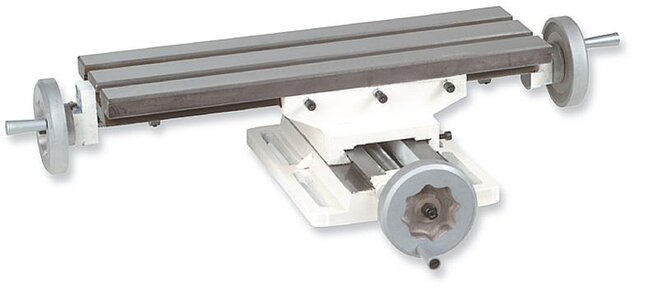
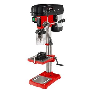

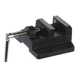
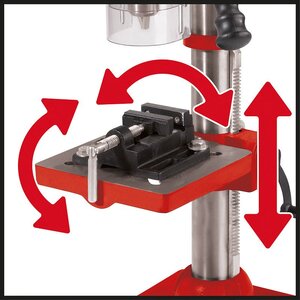
I am thinking of removing the work table on the column and mounting a coordinate table and vise on the plinth / bottom plate.
I was not able to copy the picture of the vise, but it is the one you have, two axis.
What do you think.


Hello Knut thank you for asking I feel already better still a little weak but symptom free.Hello again Tobias, Hope your health is better now, I have long considered buying a column drilling machine for various work, not just model building.
I am thinking of removing the work table on the column and mounting a coordinate table and vise on the plinth / bottom plate.
I was not able to copy the picture of the vise, but it is the one you have, two axis.
What do you think.
View attachment 352993View attachment 352994View attachment 352995View attachment 352996View attachment 352997View attachment 352998
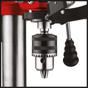
 very difficult to advise well in asking tools. Everyone has his favorites, I've read a lot about the Einhell stuff and for me it would be nothing. With such an investment I always think very long and save on quality. Of course, it always depends on your own needs, with the Einhell it already starts with the drill chuck that would be nothing for me, the bearings are also very poor and loud, etc. I would here to the Optimum OPTIdrill B 16-24H decided. For model making of course fell too extreme. The Bosch is quite sufficient for this. The coordination table seems to be okay. The one I bought I can not really recommend it is too wobbly I think there are better. I will buy this one, see link.
I hope I could help.
Mophorn kreuztisch Tischbohrmaschine 450 mm, Frässchraubstock 170 mm, Metall Professionelle Gusseisen Schraubstock für Säulenbohrer Breite Backen und den vielseitigen Einsatz, Metallisch https://amzn.eu/d/boPpwx8
Knut, those small cheap drill presses are horrible. I had one, I used it for a short time and bought a much better huge one used for very very little money that's accurate. You get what you pay for. Same with XY tables. Everything today is either cheap junk or very expensive high end stuff. You need to find something in the middle if possible.
- Joined
- Dec 3, 2018
- Messages
- 2,451
- Points
- 538

Optimum- OPTIdrill B 16-24H, this will be way too expensive for me, but you mentioned Bosch, I have looked at (PBD 40), I can afford to buy this.
Vise plus coordinate table adds up to 107.5mm in height, I think this can work together.
I check all measurements before buying this.
Just hope that this machine is stable enough.
Hope this wasn't too much of a hassle.
Greetings Knut
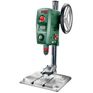
Vise plus coordinate table adds up to 107.5mm in height, I think this can work together.
I check all measurements before buying this.
Just hope that this machine is stable enough.
Hope this wasn't too much of a hassle.
Greetings Knut

Hi Knut, many modelers use the Bosch, I personally do not have it, but it is supposed to be good.Optimum- OPTIdrill B 16-24H, this will be way too expensive for me, but you mentioned Bosch, I have looked at (PBD 40), I can afford to buy this.
Vise plus coordinate table adds up to 107.5mm in height, I think this can work together.
I check all measurements before buying this.
Just hope that this machine is stable enough.
Hope this wasn't too much of a hassle.
Greetings Knut
View attachment 353248
Beautiful Joinery !!!
I wish you all a good evening, my visitor COVID has left again and I have resumed work in the workshop today. Now before I got this unexpected visitor I promised you a little description how I build my frames to come to a relatively good result. I will now make up for this and start with part 1.
Part 1
Primarily, this is about the plan the workplace and various preparations.
THE PLAN:
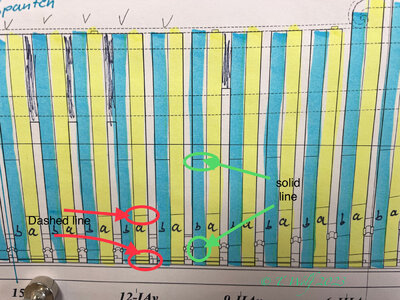
For this I have copied the plan number 5 and highlighted the frames in color, furthermore I have labeled them a and b. ATTENTION with many French ships known to me the double frames in the middle change the superstructure and the notches in keel and keelson.
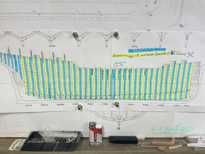
In the next step I will come to the workplace and the tools and aids used.
THE WORKSTATION:
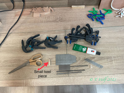
I use glass plate from an old cabinet that has been retired as a smooth base. After each gluing of the frames I clean the plate with a glass scraper or with a blade of a cutter to have a smooth surface. Various clamps and pliers to fix the two frames, a pair of scissors, files, drawing plate, glue and a small piece of keel with the right recess to fix the two frame halves.
PREPARE FRAMES:
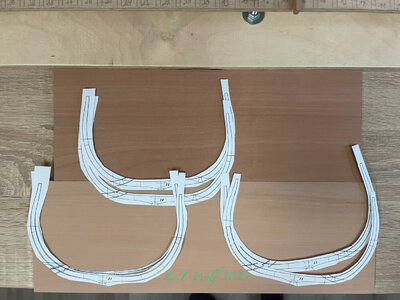
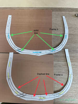
Now I cut out the copies of the frames and label them with a and b (in my example 13a and 13b). Now our colored plan comes into play again, here I have also marked the frames with a and b. I now take frame a and cut it along the dashed lines and frame b along the solid lines. I'm not sure if the technical term joints is correct, but I'll call them joints now. So you then labeled the different joints with a and b.
In the next step, I cut the individual strips of paper again to be close enough to the line.
ALIGN AND GLUING:
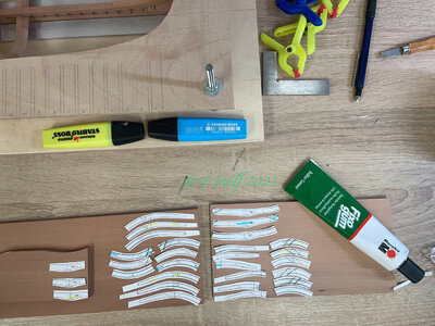
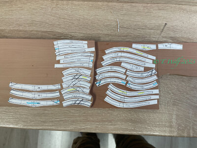
I now align the individual frame sections on my wood. In my case I used two different wood colors to get a better contrast of the individual joints, but it's still all pear. As a rule, I always do 3-4 pairs of frames, which I personally prefer to avoid monotony in the process. As you can see, I always put the same sections in a row and not frame by frame. The reason for this is simply to have less waste and I can put the strips of paper as close together as possible to only have to make one cut, saving time, wood and saw blades. To glue the paper to the wood I use fixo gum, the advantage of this glue is that it doesn't clump and can be applied evenly, the paper doesn't get soaked and it can be removed without leaving any residue.
I hope I did not forget anything. See you soon for part 2
Part 1
Primarily, this is about the plan the workplace and various preparations.
THE PLAN:
For this I have copied the plan number 5 and highlighted the frames in color, furthermore I have labeled them a and b. ATTENTION with many French ships known to me the double frames in the middle change the superstructure and the notches in keel and keelson.

In the next step I will come to the workplace and the tools and aids used.
THE WORKSTATION:
I use glass plate from an old cabinet that has been retired as a smooth base. After each gluing of the frames I clean the plate with a glass scraper or with a blade of a cutter to have a smooth surface. Various clamps and pliers to fix the two frames, a pair of scissors, files, drawing plate, glue and a small piece of keel with the right recess to fix the two frame halves.

PREPARE FRAMES:
Now I cut out the copies of the frames and label them with a and b (in my example 13a and 13b). Now our colored plan comes into play again, here I have also marked the frames with a and b. I now take frame a and cut it along the dashed lines and frame b along the solid lines. I'm not sure if the technical term joints is correct, but I'll call them joints now. So you then labeled the different joints with a and b.
In the next step, I cut the individual strips of paper again to be close enough to the line.


ALIGN AND GLUING:
I now align the individual frame sections on my wood. In my case I used two different wood colors to get a better contrast of the individual joints, but it's still all pear. As a rule, I always do 3-4 pairs of frames, which I personally prefer to avoid monotony in the process. As you can see, I always put the same sections in a row and not frame by frame. The reason for this is simply to have less waste and I can put the strips of paper as close together as possible to only have to make one cut, saving time, wood and saw blades. To glue the paper to the wood I use fixo gum, the advantage of this glue is that it doesn't clump and can be applied evenly, the paper doesn't get soaked and it can be removed without leaving any residue.

I hope I did not forget anything. See you soon for part 2
Part 2
GLUING, SAWING AND GRINDING.
Addition to gluing the paper to the wood: In the last section of Part 1 I have already discussed the adhesive I used and I would like to show you a picture again and also go into its properties again. In contrast to glue stick or Uhu liquid glue, there is no clumping (glue stick) or soaking of the paper with Fixo GUM, the paper comes off easily and there are no residues on the wood or even discoloration due to the penetration of glue into the wood
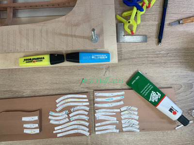
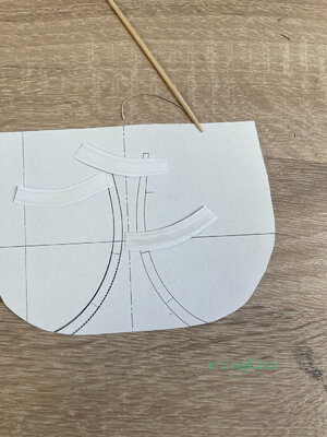
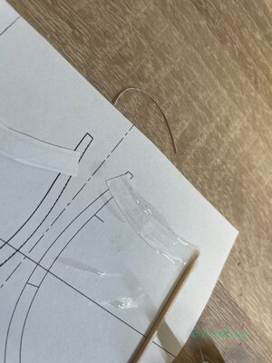
After my layout is finished I start to glue the paper. As a first step, I clean the wood with a slightly damp rag to remove dust and sawdust. Then I draw a thin line of glue on the paper and spread it with the toothpick. In the next step I glue it to the wood and make small corrections. When gluing, I pay attention to the direction of the wood grain. Always in the longitudinal direction along the length, thus preventing breakage of the wood and distortion when gluing these fine parts.
SAWING:
In the next step, I cut out my parts and prepare various cuts. I've had the experience of making these small cuts on the joints beforehand because they're more difficult to cut afterwards or there's a lot of overhang for sanding.
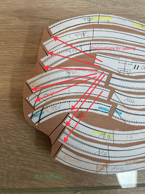
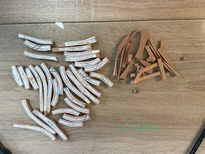
This picture clearly shows that the waste is limited.
GRINDING WITH THE DISC GRINDER:
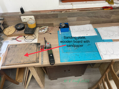
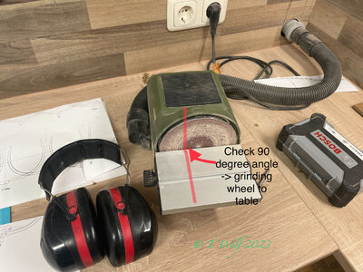
I pay attention to several things here. Before I start sanding, I check again whether the angle between the sanding disc and the table is exactly 90 degrees, then I check the speed, with my Poxxen I set it to around 3500 - 4000 rpm. a. The reason for this is that the grinding surface on the wood does not burn. Why shouldn't the wood burn at this point, you might think you can't see it anyway, but that's wrong. You will see it like a pencil mark after gluing and sanding. Before I start sanding, I pull the individual parts over a wooden board to which I have attached a sheet of sandpaper with double-sided tape. We will see this sanding plate again later in part 3 or 4. So now a little security, I wear hearing protection when sanding because the sanding and the simultaneous running of the dust extraction is loud.
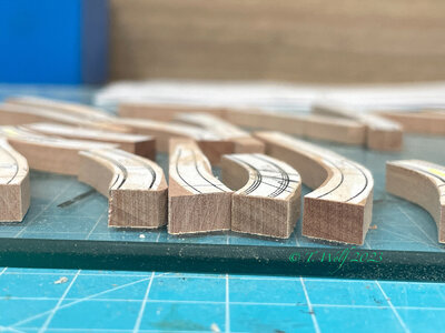
Addition: In the following picture you can see the degree created by cutting the scroll saw. To remove this grade, I use the sanding board mentioned above. If this is not done, your workpiece will not lie cleanly on the table and you will not get a clean edge on the joints.
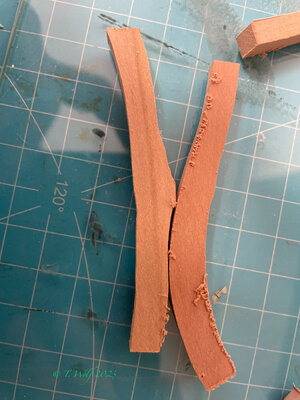
Addendum: The grinding process is the most important in the whole frame building in this construction phase. If you do not work cleanly and are not 100% accurate, your frame will not fit in the end.
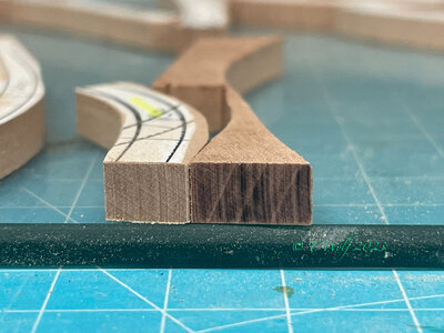
The last picture shows a test piece on the right to show what I mean by burnt wood. Tomorrow I will show you part 3 of milling, gluing, grinding with the spindle grinder. In part 4 the finish and set up in the shipyard.
I wish you a good night and thank you for your interest. If you have any questions, please let me know so that I can discuss individual points.
GLUING, SAWING AND GRINDING.
Addition to gluing the paper to the wood: In the last section of Part 1 I have already discussed the adhesive I used and I would like to show you a picture again and also go into its properties again. In contrast to glue stick or Uhu liquid glue, there is no clumping (glue stick) or soaking of the paper with Fixo GUM, the paper comes off easily and there are no residues on the wood or even discoloration due to the penetration of glue into the wood

After my layout is finished I start to glue the paper. As a first step, I clean the wood with a slightly damp rag to remove dust and sawdust. Then I draw a thin line of glue on the paper and spread it with the toothpick. In the next step I glue it to the wood and make small corrections. When gluing, I pay attention to the direction of the wood grain. Always in the longitudinal direction along the length, thus preventing breakage of the wood and distortion when gluing these fine parts.


SAWING:
In the next step, I cut out my parts and prepare various cuts. I've had the experience of making these small cuts on the joints beforehand because they're more difficult to cut afterwards or there's a lot of overhang for sanding.

This picture clearly shows that the waste is limited.

GRINDING WITH THE DISC GRINDER:
I pay attention to several things here. Before I start sanding, I check again whether the angle between the sanding disc and the table is exactly 90 degrees, then I check the speed, with my Poxxen I set it to around 3500 - 4000 rpm. a. The reason for this is that the grinding surface on the wood does not burn. Why shouldn't the wood burn at this point, you might think you can't see it anyway, but that's wrong. You will see it like a pencil mark after gluing and sanding. Before I start sanding, I pull the individual parts over a wooden board to which I have attached a sheet of sandpaper with double-sided tape. We will see this sanding plate again later in part 3 or 4. So now a little security, I wear hearing protection when sanding because the sanding and the simultaneous running of the dust extraction is loud.
Addition: In the following picture you can see the degree created by cutting the scroll saw. To remove this grade, I use the sanding board mentioned above. If this is not done, your workpiece will not lie cleanly on the table and you will not get a clean edge on the joints.


Addendum: The grinding process is the most important in the whole frame building in this construction phase. If you do not work cleanly and are not 100% accurate, your frame will not fit in the end.
The last picture shows a test piece on the right to show what I mean by burnt wood. Tomorrow I will show you part 3 of milling, gluing, grinding with the spindle grinder. In part 4 the finish and set up in the shipyard.
I wish you a good night and thank you for your interest. If you have any questions, please let me know so that I can discuss individual points.
Last edited:
Once again, thank you Tobias for your clear and precise instructions.
Hallo Tobias, very cleanly structured and very nicely edited, I like it very much.
Once again, thank you Tobias for your clear and precise instructions.
Oliver thank you very much for the feedback as well as Adi.Hallo Tobias, very cleanly structured and very nicely edited, I like it very much.
I hope you can forgive me the one or other translation error.
Very good tutorial and explanations - Bravo my friend
BTW: Which kind of glue are you using sticking the paper to the wood - I have very good results with fixo-gum - you can remove the paper and glue afterwards without any problems
BTW: Which kind of glue are you using sticking the paper to the wood - I have very good results with fixo-gum - you can remove the paper and glue afterwards without any problems


