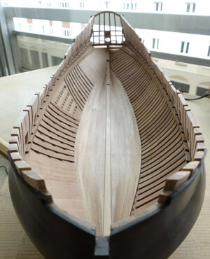
LE ROCHEFORT - Harbour yacht from 1787 1:36 by Tobias (Monograph by ANCRE)

Thank you Adi, Splitter, Jim and Paul for your words of appreciation.
Very clean work, very clear and extremely informative.
Adi it is good to get your feedback, thank you.
Thank you for this tutorial. While I am not a part of this group build, I still learned a lot.
Paul, as you know, you don't have to be part of this group, so I'm even more pleased that you keep stopping by, thank you.
Master at work!! Love the way you build: Simple with precision!
Jim I am still far away from the master and try as good as possible to represent my work steps. I am sure there are other ways to get a good result, but thank you.
Tobias, again Fantastic and clear explanation and clear photos Thumbs-Up
Splitter I'm glad if my instructions are understandable, if you have any questions I'm happy to help, thank you.

Translated with www.DeepL.com/Translator (free version)
 
Thanks again Tobias for your precise instruction. I do have a couple of questions that I’m struggling to understand.
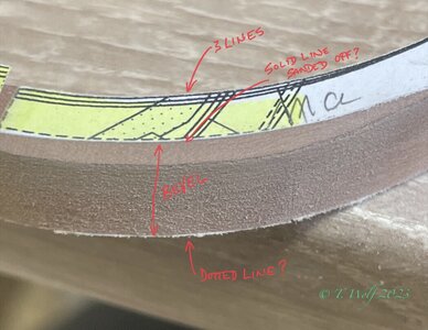
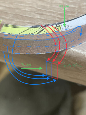
I annotated your photo in order to clarify my questions.
1. Some of the frames have multiple lines. I’m assuming we sand to the outer solid line. What do the other lines represent?
2. I’m assuming we sand to the solid line on the “a” side and the dotted line on the “b” side to create a bevel on the outer curve, correct?
3. On the inner curve do we follow the same principle of solid line to dotted line?

Adrian’s book says, “We must remember that the solid lines are located on the floor-timber layer (“a” side?) and the dotted lines on the half floor-timber layer (“b” side?.” (Page 27). So perhaps I answered some of my own questions… ‍♂️

2B9CC9D5-B336-470A-A5F3-D00658D2A2C1.jpeg

Last question (this time…) Adrian, as well as the monograph, discuss ”bolting” the frames together with 0.40mm ebony. I guess this step would only be needed if I’m building an admiralty or open sided version, correct?

Thanks again for your patience.
Olivier
 
Thanks again Tobias for your precise instruction. I do have a couple of questions that I’m struggling to understand.
I annotated your photo in order to clarify my questions.
1. Some of the frames have multiple lines. I’m assuming we sand to the outer solid line. What do the other lines represent?
2. I’m assuming we sand to the solid line on the “a” side and the dotted line on the “b” side to create a bevel on the outer curve, correct?
3. On the inner curve do we follow the same principle of solid line to dotted line?

Adrian’s book says, “We must remember that the solid lines are located on the floor-timber layer (“a” side?) and the dotted lines on the half floor-timber layer (“b” side?.” (Page 27). So perhaps I answered some of my own questions… ‍♂️

View attachment 355962

Last question (this time…) Adrian, as well as the monograph, discuss ”bolting” the frames together with 0.40mm ebony. I guess this step would only be needed if I’m building an admiralty or open sided version, correct?

Thanks again for your patience.
Olivier
Hello Oliver, well I admit this is all a bit confusing at first and believe me, I felt no different than you. I try to explain it:
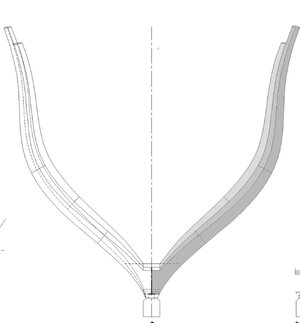
1. on the basis of my example frame No. 11. we have always only one view in the plan, the peculiarity with the frames from the middle mirrors the whole. In our case 1-15 we see from the middle of the ship towards the bow and 16-32 then towards the stern. So in my case the yellow or a marked parts is the first half (towards the bow) and the blue or b (towards the stern). Our ship makes an arc from the center seen in both directions. These three lines you see (continuous or broken) are quite easy to interpret. Our two halves that we have glued together have in the end each a leading and trailing edge, thus creating three edges leading, middle and trailing edge.
Three edges are shown in the plan once as broken lines and once as solid lines to get a 3D effect. Depending on which side you look at your insteps from, the lines should also change. What is interrupted on one side should theoretically be continuous on the other. But in our case they don't because we only have one view from which we made a copy.
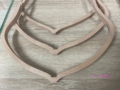
In the Colored Map I showed in Chapter 1, I capture this reflection, so a or the Yellow Frame is always the one looking at me. Now for the sanding of the frames, here I ignore the middle line, I turn to the innermost one that is the point to which I make my bevel and the outer line is already given that is my end of the bevel on the back. It is important that you make sure that you make the same slope inside and outside. The cross-section must be a kind of rhombus and not a trapezoid.

2. Now for the nails, if you plan to plank everything you can omit those (not everyone is as crazy as I am ROTF). But what would be a shame if you planked everything because you wouldn't see your great work at all. But that is your decision alone.
CB98D03E-EFA6-4D5D-924C-73A10D35B40B.jpeg

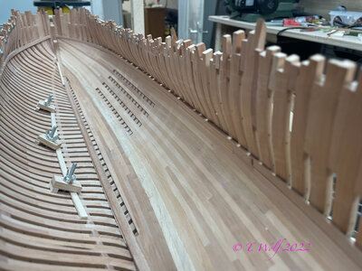
Here is another picture that should show the 3D effect and maybe also bring some clarity.

B9113DBD-3692-4EE9-A619-0AB6F463D2DA.jpeg

Like a picture of my La Palme with the nails.

492AA0C8-F947-418D-A4A7-21E12F6E1BC7.jpeg
 
Hello Oliver, well I admit this is all a bit confusing at first and believe me, I felt no different than you. I try to explain it:
1. on the basis of my example frame No. 11. we have always only one view in the plan, the peculiarity with the frames from the middle mirrors the whole. In our case 1-15 we see from the middle of the ship towards the bow and 16-32 then towards the stern. So in my case the yellow or a marked parts is the first half (towards the bow) and the blue or b (towards the stern). Our ship makes an arc from the center seen in both directions. These three lines you see (continuous or broken) are quite easy to interpret. Our two halves that we have glued together have in the end each a leading and trailing edge, thus creating three edges leading, middle and trailing edge.
Three edges are shown in the plan once as broken lines and once as solid lines to get a 3D effect. Depending on which side you look at your insteps from, the lines should also change. What is interrupted on one side should theoretically be continuous on the other. But in our case they don't because we only have one view from which we made a copy.
In the Colored Map I showed in Chapter 1, I capture this reflection, so a or the Yellow Frame is always the one looking at me. Now for the sanding of the frames, here I ignore the middle line, I turn to the innermost one that is the point to which I make my bevel and the outer line is already given that is my end of the bevel on the back. It is important that you make sure that you make the same slope inside and outside. The cross-section must be a kind of rhombus and not a trapezoid.

2. Now for the nails, if you plan to plank everything you can omit those (not everyone is as crazy as I am ROTF). But what would be a shame if you planked everything because you wouldn't see your great work at all. But that is your decision alone.

View attachment 356013

Here is another picture that should show the 3D effect and maybe also bring some clarity.

View attachment 356014

Like a picture of my La Palme with the nails.

View attachment 356015
Tobias, once again I thank you. I believe it’s time for me to start assembling the frames. I’ll start with the easy ones like 14 - 17…
 
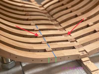
Good morning all. For all those who are already further in the process like me please pay attention to more little things. Here is an example of my La Palme, still need to install the keys and connecting wedges (red arrow).

6A14C365-EF49-414C-8F8B-A3A5C105F439.jpeg

To get a clean and straight line I always kept the same distance to the keel and connected the marked areas with a bendable wooden strip (blue line). A special feature of Le Rochefort is that the connecting wedges are embedded in the frames about 0.7mm. This means that you have to mill the frames at this point (green line).

B0095655-0CDF-4255-A3CD-ABD574A8134E.jpeg

@Splinter since you have already glued your formers you have two options for the wedges on the formers.
1. fit the wedges and glue them in without the recess in the frames (would be perfectly ok).
2. you mark the spots and file out this area and push in your wedges.
 
Good morning all. For all those who are already further in the process like me please pay attention to more little things. Here is an example of my La Palme, still need to install the keys and connecting wedges (red arrow).

View attachment 356636

To get a clean and straight line I always kept the same distance to the keel and connected the marked areas with a bendable wooden strip (blue line). A special feature of Le Rochefort is that the connecting wedges are embedded in the frames about 0.7mm. This means that you have to mill the frames at this point (green line).

View attachment 356637

@Splinter since you have already glued your formers you have two options for the wedges on the formers.
1. fit the wedges and glue them in without the recess in the frames (would be perfectly ok).
2. you mark the spots and file out this area and push in your wedges.
Thank you Tobias

I will go for option 1
 
Good morning all. For all those who are already further in the process like me please pay attention to more little things. Here is an example of my La Palme, still need to install the keys and connecting wedges (red arrow).

View attachment 356636

To get a clean and straight line I always kept the same distance to the keel and connected the marked areas with a bendable wooden strip (blue line). A special feature of Le Rochefort is that the connecting wedges are embedded in the frames about 0.7mm. This means that you have to mill the frames at this point (green line).

View attachment 356637

@Splinter since you have already glued your formers you have two options for the wedges on the formers.
1. fit the wedges and glue them in without the recess in the frames (would be perfectly ok).
2. you mark the spots and file out this area and push in your wedges.
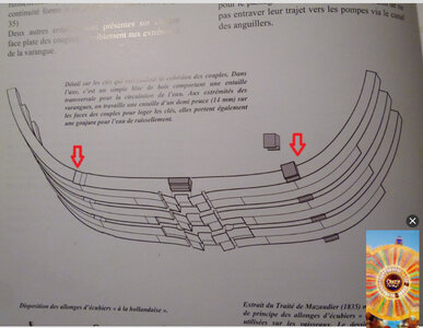
If I might bother you Tobias...why are those filler blocks concave on the outboard surface?
 
If I might bother you Tobias...why are those filler blocks concave on the outboard surface?
Hi Paul, I can't say for sure. At La Palme they are straight. My guess is that water that is in the upper area can drain down better and then be pumped up with the pumps. The inner planks at Le Rochefort are completely closed in contrast to La Palme. As I said it is only a guess, I am sure that @Frank48 or @Uwek know the answer.
BB22A8EF-2899-4A3F-9AA4-86D0FE685DC3.jpeg

Or also very too beautiful at the great Schwerster La Renommee of Patrik

5618E3C2-5159-4E9F-8792-B1F53E378BEB.jpeg
 
Last edited:
Hallo Paul, sie sind für den Wasserdurchgang zu den Sammelkanälen auf der Unterseite des Rumpfes, es tut mir leid, Tobia, dass er in Ihren Garten eingedrungen ist
[/QUOTE

Hi Frank, that's why I mentioned you to do exactly that and enlighten us. So I was correct in my assumption. Thank you Frank and by the way, your opinion and your knowledge is important to me, so I'm always happy to.
 
Dear Tobias
I am sure that your precise work on the ship and the detailed guidance you provide will faithfully serve those who are currently building under your guidance and those who will come in the coming years.
Unfortunately I missed the impressive progress in your work, I would like to praise you for the high-quality result you have achieved and also to congratulate you on your recovery from the kovid. Unfortunately, construction logs and people I define/mark for monitoring, the request works for several weeks and then disappears without receiving an indication and I find this out too late. That's why I check monthly for new posts on days I remember that interest me .
In short, dear friend, happy for your recovery and return to the creation of the model :) Thumbsup :D
 
Hallo Frank, deshalb habe ich dir erwähnt, dass du genau das tun solltest und uns aufklärst. Also lag ich mit meiner Vermutung richtig. Danke Frank und übrigens, deine Meinung und dein Wissen ist mir wichtig, also immer gerne.
Hallo Tobia, danke für die netten Worte über mich, aber ich versuche immer nur das zu vermitteln, was ich weiß, Frank,

Hello Tobia, thanks for the nice words about me, but I always try to convey what I know Frank,
 
Dear Tobias
I am sure that your precise work on the ship and the detailed guidance you provide will faithfully serve those who are currently building under your guidance and those who will come in the coming years.
Unfortunately I missed the impressive progress in your work, I would like to praise you for the high-quality result you have achieved and also to congratulate you on your recovery from the kovid. Unfortunately, construction logs and people I define/mark for monitoring, the request works for several weeks and then disappears without receiving an indication and I find this out too late. That's why I check monthly for new posts on days I remember that interest me .
In short, dear friend, happy for your recovery and return to the creation of the model :) Thumbsup :D
Dear friend, thank you for your words. It's no different for me, Shota, I have to constantly update and click through the menu to be up to date.
 
Back
Top