Don,
Important note.
The set of plans you are using includes all the information needed to build a complete 2-layer frame.
My set of plan does not so I took some liberties in tracing and labeling a simplified version of those (smaller number of parts) to fit my purpose.
But in the end, the step-by-step technique I use to build each frame is the same. This technique is the one I chose to use. It is most certainly not a better technique as each modeler may proceed with some differences.
Now… on with the description…
Building a 2-layer full Frame: mid-ship frame with no bevel which can also be referred to as a “square edged frame”.
Please note that building a frame closer to the front or the back of the ship is very similar, although a bit more confusing because of the addition of bevel lines both on the inside as well as the outside of each frame. None the less, the technique is the same, it is just a matter of getting used to having the extra lines. This is the reason why, I normally suggest starting with the mid-ship frames: no bevel or a bevel that is so minimal that most of the time one could or should not bother cutting that bevel. These bevels are so slight that one can easily take care of them as the framing is sanded on the inside and outside the hull.
For the purpose of this demonstration, this frame is composed of 7 parts / pieces representing the 2-layer frame.
Whether your set of plans contains the full information including the outline of each part (ie: all futtocks, floor-timbers, crotches, etc) or the parts are drawn at your discretion, all this makes no difference. The parts are contained and labeled within the full pattern used for the construction. All parts of each frame may or may not already be labeled on the plans used. If not, it is simple enough to allocate a number, letter or combination of both to identify each part so that parts for each layer can be separated in whatever way makes sense to the individual builder. The frame is being built in 2 layers. Following a plan set showing all information the patterns may show the 2 layers indicated by solid and doted joint lines. The solid lines representing the forward layer (face) of the frame, the doted line representing the back layer (face) of your frame.
In this (my) case, again, because my set of plans does not show this information, I am including 1 image showing the full pattern and 2 more images braking down the different layers: RED = forward / front face, GREEN = back face
Full pattern of one single, 2 layer frame.
Fig 1
Because I worked out the location of each joint for my own purpose (and to mention “not following what would be historically correct”), I did not use solid and doted lines to identify the joint of parts according to which layer they belong to. The composition of the frame has been simplified by reducing the number of part / futtocks.
View attachment 127762
Forward facing frame layer:
Fig 2
View attachment 127765
Back frame layer:
Fig 3
View attachment 127766
________________________________________________________________________________
Frame construction part one
Tracing the pattern to wood.
Some builders will print copies of the overall frame, then cut out each part and glue these pattern to the sheet of wood used.
In my case, I like to take the full pattern and transfer each part using tracing paper.
Whatever way is used make not much of a difference as it really is a matter of preference. Both way have “pros and cons”.
Patterns transferred to the wood:
Fig 4
View attachment 127767
So the image shown above shows the patterns transferred to the wood, trying to have the length of the pieces running along with the wood grain. In this case, because I simplified the composition of the frame with a lower number of parts, some of the futtocks are much longer than they should be, had the frame been broken down according to period practices, it was difficult to have the length of the parts follow the wood grain: shorter parts work better. As indicated earlier, this frame is composed of 7 pieces: 3 for the front layer and 4 for the back layer. Parts / pieces have been identified as was done in the 2 previous images.
Once again, the breakdown of the frame is not historically correct. The frame could have been broken down into more pieces, but in the end it makes no difference as far as the actual technique is concerned.
Frame construction part two
Cutting the different elements composing the frame.
Again, to each his or her own, I my case, the tool of choice is a coping-saw.
One will note that the contour of each piece was done leaving between 1 and 2 millimeters extra material all around.
Fig 5
View attachment 127768
The image below is a view of the parts forming the 2 layers.
The 3 pieces at the bottom are the parts needed for the forward face of the frame. The parts are labeled F1, F2 and F3 as was done for the image shown as Fig 2.
The 4 pieces above are the parts needed for the back face of the frame. The parts are B1, B2, B3 and B4 as labeled in Fig 3.
Fig 6
View attachment 127770
At this point, the frames parts can be bundled and set-aside until frame assembly.
I should also note that working on several frames at the same time saves lumber as similar pieces can be traced or laid next to each other: this is relative to the shape of the pieces as well as length, etc…… Then cut and sorted out as long as each piece has been identified with frame and part number.
Next, I will document the following steps in the construction of a frame:
Getting the parts ready for assembly, then assembly, then fairing or squaring the edges.


 AN UNDERSTAND WHAT TO DO, I sure hope I am not being a PIA if so please tell me, the pictures are of frame No.6 showing the markings of the edges and leaving a little meat on both sides, an the next set of patterens i will leave the black line visable, again THANKS SO MUCH APPRECIATED
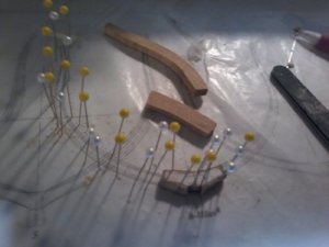


")
