LE ROCHEFORT

First of all, Gilles many, many thanks for the very descriptive explanation. This is kinda an eye-opener (for myself). Correct me if I wrong to better understand the drawings (see edited picture with orange arrows). Here is the question: The joint between futtock numbered '1' and '3' for both frames?

View attachment 127916

Hi Jim

Yes you have interpreted everything correctly including what,to me,is obviously a mistake on the drawingsThumbsupThe joint is only on the front frame.The numbering is the clue.The futtocks are numbered each end on the drawing.Futtock 2 is shown to overlap either side of this continuous line going by the numbering.No numbering on JC Lemineur's drawings,so as you can imagine they are good fun:oops:

Kind Regards

Nigel
 
Hi Jim,
Funny, how I would pick a frame that has an error ......
As confirmation, here is a shot of the same area but including the next frame on either side.

As Nigel points out, in this case, the numbering would be the clue.
This said, With or Without the numbering, this is the type of very minor thing one would "discover" while building each frame of the model. During the construction, the process of building frames become quite automatic in your mind, that there is a good chance that such error may be overlooked: the basic structure of every frame being the same.
** That is why I keep repeating or recommending all, who work on this type of framing, to begin frame construction with a simple 2-layer "square" frame: a frame that does not involve any bevel. Simply put, once you understand that each frame is basically built the same way, every futtock (part) composing the front layer overlaps 2 futtocks (parts) on the back layer, and vise-versa, things become quite easy to grasp.

On a side note, The framing of the ship Nigel is building is much different and much more complicated as it does not follow the same 2-full layer frame construction: but the idea is kind of similar.


_DSC0633 aa.jpg

Of course, such error does not take anything away from the quality of the monographs. Small or large ship, the drawings are complex and one must have a basic understanding of how each structure is built.


G
 
Last edited:
GI LLES AND NIGEL TWO MASTER BUILDERS GIVING HELP TO INTERMEDIATE AND MUCH MORE ADVANCED MODELERS THIS IS WHAT SOS IS ABOUT, AND I THANK YOU FOR YOUR INPUT AND YOU PATIENCE, now showing frame No.6 with the pattern attached and I will leave it there, now the hard part I am showing the 2nd part of the double frame ( facing aft) just dry fitting the futtocks, I HAVE NO IDEA IF THIS IS THE CORRECT WAY TO DO IT have tried other ways NO GOOD, what i do is use the forr timber as my guide NOW I AM USING THE LINES THAT NIGET SUGESTED AS MY GUIDE BOTH FOR THE ATTACHED FUTTOCK AND THE FRAME PLANS, then glueing them up, I HAVE TO TWAK THE KEEL NOTCHES A LITTLE, ALSO MY MARKING ON THE FRAME PATTERENS LEAVES A LOT TO BE DESIRED, NEXT PAIR WILL USE MY SHIPS CURVES TO KEEP THE LINES UNIFORM ABOUT 1.5mm, I HOPE I AM RIGHT AT THIS POINT AND I WILL DO FRAME No.8 OVER AGAIN, lEARNING SO MUCH
 
GI LLES AND NIGEL TWO MASTER BUILDERS GIVING HELP TO INTERMEDIATE AND MUCH MORE ADVANCED MODELERS THIS IS WHAT SOS IS ABOUT, AND I THANK YOU FOR YOUR INPUT AND YOU PATIENCE,

Hi Don,
I will speak for myself only ........ Me, A master builder? Nope ....... Please do not go around spreading rumors.
Thank you for your appreciation.
G.
 
Last edited:
IF NOT YOU GILLES WHO LOL, showing the second of the double frames(stern side, I have tried to do it it brick fashion BAD, BAD, so i do it this way using marks as my guide the question is do I sand it after gluing or before, I have tried it after gluing was not to happy with the results so will try it this way, GILLES if I wait till after the frames are made to do the keel and keelson notches would have no room to use my mill as I prepare the floor futtocks I mill the notches am I right,, again so much help and patience, 20200111_233248.jpg20200111_233636.jpg
 
On with the second part on building frames....... (sorry for the delay but life gets in the way.....

Frame construction part Three
Getting the parts (floor-timber and futtocks) ready for assembly


The only steps really required before assembly are:

a) Sanding the parts’ joint line: the straight joints connecting each part to assemble the frame.

b) Cleanup of the edges of each part / piece composing the frame. During cutting as well as square the joint lines, small curled burrs have been created on the lower edges of the parts by the blade and the sanding disk. These must be removed. This operation can be done with a very, very light sanding: usually going over the edges very, very lightly with a file or sandpaper as to not round the edge. The removal of the burrs will allow for the frame parts to lay perfectly flat in view of assembly.

20200112_153616.jpg
Fig 7


Once that is done, pieces of the frame are dry fitted over the pattern to make sure everything lines up. Some very minor adjustment may be needed on some of the joint line: proceed very carefully as to not over sand the joint. If doing so, the part will end up being short and must be redone (a new one needing to be cut).
Again the contour of the parts still has 1 to 2 mm extra material. Depending on the frame structure, the “floor-timber” or base of the frame notch (es) to be fitted to the keel can be cut at this point or not. Some floor-timbers are fitted with a different size notch to be cut in the front layer compared to the back layer. In this case, yes the notches should be cut. In my case, for the purpose of this demonstration, I am building a frame with a constant notch through the base of the frame so I elect to cut it at a later stage.

Dry fitting……

This operation is straightforward. If the joints have been prepared right, the parts should fit the pattern.

Please note that the joint lines are most important in order for all the parts to line up correctly for the parts to fit the pattern and end up with a tight joint. These should be taken care of with precision in regards to all angles: width and thickness of the part.

Although dry fitting can be bypassed, the modeler may find this step re-assuring before final assembly. This step confirms that the joints are true and lined up with the references on the frame plan and that the actual frame assembly follows the overall pattern lines.

Fig 8
20200112_160620 a.jpg

Fig 9
20200112_160759 a.jpg


Frame assembly
As usual “to each is own” technique.
As far as I am concern, here are the steps I follow:

The frame parts are laid down over the entire frame pattern. Starting with the back layer, I lay down the pieces one by one applying glue to each joint as I move along from one part to the next. The first parts to be fitted are the 2 centre timbers (one at a time), applying glue between the 2 parts (joint). Then, I work my way up the frame. If working on a frame layer built with more parts than the one shown in this demonstration, I alternate placing parts on either side. The back layer of this frame being simply built with only 4 different timbers, gluing parts together is straightforward.

Once the back layer has been assembled, right away I move on to laying down the front layer over top. Again staring with the center part (floor-timber) then the others: all the while being careful not to move the parts already in place. For that, one needs to have a fairly light hand as once glue has been applied to the face in contact with the bottom layer, parts become slippery.

Anyway, if all was good during the dry fitting, all should be good in this step. Again, handle and align parts with care.

Assembly can take place atop a sheet of glass. Once the 2 layers have been assembled, a second sheet of glass can be laid over top + some weight until the glue is dry.

Squaring the edges of the frame.

Once the frame is dry, the edges of the frame can be cleaned up and squared. At this stage, I do the same whether the frame is to be beveled or not.

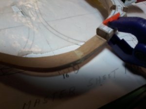
The photo below show a frame, which outside edge has been cleaned up and squared.

Please note that the extra material left around the frame pattern amount to about 1.5mm. This can be further reduced down to just under 1mm. I sometime leave a little extra until all the frames are built, then dry fitted to the keel so that I can judge the overall shape of the hull (no severe hollow areas). If everything is good at that point, I may reduce to 0.5mm. Not doing so would just mean more time spent at sanding the hull when all the framing has been assembled. Anyway, that would be another subject…..

Fig 10
20200112_163631 a.jpg

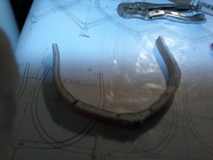
The photo below shows a frame, which inside edge has not been cleaned up and squared yet, but it is the next step.which I did not bother photographing.
Fig 11
20200112_163714 a.jpg


Sanding the edge can be done different ways; a stationary drum sander or oscillating sander is easier as far as the inside curved edge is concerned.

At this point frame can be put aside. Work can resume with the rest of the frames. Beveled frames can be treated the same way up to this stage: before beveling.

G
 
showing the second of the double frames(stern side, I have tried to do it it brick fashion BAD, BAD, so i do it this way using marks as my guide the question is do I sand it after gluing or before, I have tried it after gluing was not to happy with the results so will try it this way,

Not sure I understand your question.

if I wait till after the frames are made to do the keel and keelson notches would have no room to use my mill as I prepare the floor futtocks I mill the notches am I right

Yes you are right. Your frame are built with different notches from front to back layer, so yes you should cut the corresponding notches.

On a side note about the images showing the clamping.... for dry fitting I am guessing.
This kind of clamping will only give you misery or headaches. And if you do that for the assembly (gluing) of your frame....... such clamps = trouble.

G
 
Last edited:
One final added note on building frames:
When it comes to beveled frames, at some point, one will eventually have to transfer the bevel lines to the back side of the frame as well.
Here is my take on the subject.....
The trick is to make sure that the lines are the same on both front and back face.
- First, transfer the entire frame pattern, including all lines (solid and doted) on a sheet of tracing paper before frame assembly begins.

-Second, use this sheet of tracing paper as a guide during the assembly of the frame. this is where the back layer rests on.

-Third, When assembling the frame, using a "glue stick" (school of office type glue stick), apply glue to the back face of all back layer parts. Essentially, gluing the back layer parts to the tracing paper. Do remember to apply your regular wood glue (or whatever other glue you used for the actual assembly) to the joints.

-When your frame is completed and everything is dry, just cut off the tracing paper around the frame. You may also peel the tracing paper off: the pencil lines will be transferred to the layer of glue between the wood (back face of the frame) and the tracing paper sheet.

In conclusion, because only one frame pattern is used, the lines will automatically be the same of both side of the frame: eliminating a somewhat tricky operation of later tracing those bevel lines. The glue can later be easily scraped off.

Partial lines are visible in the photo below. This is the result of the glue applied to the joints.
had this been a beveled frame I would have the complete matching set of lines on both faces. But you get the idea.

20200113_084803 a.jpg

G.
 
again just a wonderful guide fantastic, i could not continue without it, just thanks again, a couple of questions, what clamps do you use, and yes they were for dry fitting, showing completion of frame No.6 re-do the first part facing bow was done my old way the second part was done by gilles and nigels way much, much,better joints getting better also, not quite there yet but making progress, question i like to mark on the frames the deck locations and also THE DECK CLAMP LOCATIONS the plans do not show the deck clamps how do you determine that20200113_044859.jpg
 

Attachments

  • 20200113_045001.jpg
    20200113_045001.jpg
    132.5 KB · Views: 2
One final added note on building frames:


In conclusion, because only one frame pattern is used, the lines will automatically be the same of both side of the frame: eliminating a somewhat tricky operation of later tracing those bevel lines. The glue can later be easily scraped off.

Partial lines are visible in the photo below. This is the result of the glue applied to the joints.
had this been a beveled frame I would have the complete matching set of lines on both faces. But you get the idea.

View attachment 128232

G.


Here is an update the the post quoted:

Again this is not a frame needing to be beveled but just for demonstration purpose.........

This 1st photo shows the frame once it was removed from its drying position: which by the way, it is just sandwiched between 2 pieces of glass and a bunch of weights on top. No clamps......
So this is the front face of the frame. Note the sheet of tracing paper used to lay the frame for final assembly. The frame outline is traced on that sheet.


_DSC0637 a.jpg

The second image shows the tracing paper removal from the back face of the frame. Note that the pencil line (frame outline) is capture into the craft glue.
I guess I missed a spot.......

_DSC0638 a.jpg

And now, the paper as been removed. The full frame outline is there, except for the spot I missed.

So in the end, the outline used to line up all the parts is now on both the front and back face of the frame.

_DSC0639 a.jpg

At this point, the edges can be squared, bringing the extra material left around the outline down to between 0.5 to 1 mm closer to the outline.

G.
 
again just a wonderful guide fantastic, i could not continue without it, just thanks again, a couple of questions, what clamps do you use, and yes they were for dry fitting, showing completion of frame No.6 re-do the first part facing bow was done my old way the second part was done by gilles and nigels way much, much,better joints getting better also, not quite there yet but making progress, question i like to mark on the frames the deck locations and also THE DECK CLAMP LOCATIONS the plans do not show the deck clamps how do you determine thatView attachment 128262

Don,
Frame is looking good.
Please note that you can leave as much extra meat as you want: do not be shy, so you can increase that. It is best to have too much than not enough.

Remember that dry fitting is done for 2 reasons:
1/ make sure the frame parts are cut according to the corresponding pattern, primarily to make sure that the joint between each piece is cut right.
2/ make sure of best possible fit of all parts following the line pattern of the entire frame (there should be no gap between the parts).
So to properly dry fit all the cut pieces, you need to make sure all the joints are as tight as possible before applying the glue. There seems to be gaps were the tight joints are supposed to be. But I may be too critical....

Once your frame has been assembled / glued together, and after the glue is cured (several hours), you can always reduce the meat down closer to the frame outline (the outside lines.
__________________________________________________

As far as clamps are concerned for dry fitting and assembly,..... I do not use any. Your frame should lay on a flat surface to be sure all is well. And for the assembly, freshly applied glue is slippery, so any squeeze clamping will make the parts slide:
Like I said earlier, dry fitting is just a matter of carefully laying down the parts over the pattern, being careful not to move anything in the process. You are dry fitting frame parts to make sure they all fit together well with the pattern.
Dry fitting can be done one layer at a time: dry fit the entire 1st layer to make sure it follows the pattern. If happy with the fit, push all the parts away from the pattern and proceed with the 2nd layer,

Assembly, you can also do that one layer at a time. Lay down the bottom layer part by part applying glue to the joint edges. When the bottom layer is done, just do the same for the second layer: like a pile of big books (the one directly over the frame should be a hardcover) laid over the frame and you do not to place all the weigh at the same time.
You do not absolutely need glass to sandwich the frame for drying. You just have to make sure your surface is flat and the weight you put on top is actually larger than the frame itself.
The glass helps though: if only because the glue that may squeeze off the joints won't stick to the glass.

The bottom line is simple, making frame is fairly easy, it is repetitive and, like everything else, it must be done while paying attention as it should be precise.

As for the deck-clamp, I would not worry about it that at this point. It is good to get ready for future tasks but right now you are building frame and getting better at it.
G.
 
Last edited:
I can fully underline the words of Gilles, do not use clamps for making the frames.
Here you find one post of my Salamandre, where I show how I am fixing the elements of a frame
and secure everything afterwards with a heavy glass plate - and some weights on top -> with this no movements of the parts
 
Thank you Uwe for posting the links. ThumbsupThumbsupThumbsup
You deserve a "double" or "triple" like for that.......

THE DECK CLAMP LOCATIONS the plans do not show the deck clamps how do you determine that

As previously mentioned, this (the deck-clamp) should be the least of your worries at this point.
Your first priority is to master frame building, so it should be the only thing on your mind for now. Once you have achieved that and once you have fitted all your frames onto the keel, this is when framing becomes a "bit" more difficult with the Hawse-timber and stern framing.
G.
 
One point I forgot to mention in my early posts is a very important one. It may be obvious to some but not so to others.

Explanation about why it is a good idea to leave extra material around the outline of the frame parts and, as a result, the overall outside lines of a fully assembled frame.
This is done not so much for the actual assembly of the frame itself, although it does help a bit while lining up the separate parts, but in case of minor errors when the hull framing has been completed.
Once all the frames are done, the bow and stern have been framed, it is time to sand everything down to the right timbering thickness, and hull shape: both inside and out. During the construction of individual frames, the fitting and assembly of these frames to the keel some minor errors may have occurred. These errors may have created shallow hollow areas in the overall shape of the hull framing. This extra material / "meat" is there to compensate for that.

The amount of extra meat is subject to how confident the builder is in the precision he / she has achieved in all the components going into the framing of a hull.
For most it is a "be safe or be sorry" situation......so that extra material is the "be safe" solution.

G.
 
Last edited:
hi GILLES and all, when i started this build( first complete scratch build and first FRENCH ship) i had to get use to unfamilar terms an plans so i started out of sequence by doing some making of other parts as you can tell from earlier posts such as cutting out HAWSE TIMBERS an STERN PARTS came out ok i think just cut and bagged, now on to continue the frame building, i have problems with frame No.2 and other frames showing top timbers, will show pictures of plans latter today. THANKS Don
 
have not posted in a few days but busy building frames have re-done four of them and doing 2 more FRAMES No.1and2 (FRAME ONE FOR THE 5th time, pictures showing frame 8 it is a re-do i took it down very close to the finish line need a little more one one side i did this to see how it comes out, also showing FRAME No.2 with the added top timber on the frame drawing it shows the top timber facing the BOW (if i am correct) but the profile shows it facing the stern, NEED HELP ON THIS ONE, also showing the frame No.1 preparing to cut it out, am i right showing the matching lines to the pattern. 20200118_195044.jpg20200118_195720.jpg20200118_200103.jpg20200118_202529.jpg20200118_204809.jpg
 
a) I understand your question regarding Frame 2.
Just to make sure, I am posting the question on Gérard's forum.
Do not cut it yet, wait for definitive answer.
________________________________________________________________________

b) Seems like you are having trouble with the meat around the outline of your frames.
You want them to look too good too soon. Be patient.... reducing the amount of meat can wait....

2 quick photos:

Here is what my frames look like after assembly

20200118_195634 a.jpg

And here after squaring off the outside edge. Same frame and the inside edge has not been squared yet.
Note that there is more than twice the meat on the inside (not squared) edge compared to the outside edge (squared) .

20200118_195748 a.jpg

In the end, you are better off leaving too much meat than not enough. Leaving more only means more sanding once your framing is to be sanded down the road.

I think you are too used to kits where everything is cut at close tolerance and fits well because it has been tested. Scratch building is different everything your do has an impact on the next step.
Because you are making all the parts yourself, again, "better be safe than sorry". It is no fun to keep making the same frames: and you are supposed to be having fun. So leave more meat until you know you can sand it off.


G
 
Last edited:
Back
Top