Enjoy some time off, will wait until for you to return! 
-

Win a Free Custom Engraved Brass Coin!!!
As a way to introduce our brass coins to the community, we will raffle off a free coin during the month of August. Follow link ABOVE for instructions for entering.
-

PRE-ORDER SHIPS IN SCALE TODAY!
The beloved Ships in Scale Magazine is back and charting a new course for 2026!
Discover new skills, new techniques, and new inspirations in every issue.
NOTE THAT OUR FIRST ISSUE WILL BE JAN/FEB 2026
You are using an out of date browser. It may not display this or other websites correctly.
You should upgrade or use an alternative browser.
You should upgrade or use an alternative browser.
Lempi, a steam powered half open launch built in 1877 in Warkaus, Finland
As promised, a small update after having returned from our holiday trip. A bit earlier as planned, because very warm weather melted the snow from our skiing tracks almost completely.
As I told earlier the hull was sent to a professional glassfibre shop for making a mold of it, and laminate three final hulls for all of us. The idea was that rows of rivets would be copied into the mold and could be seen on the surfaces of final hulls. That succeeded completely, and it was nice to receive nicely made hulls from the shop for further building.
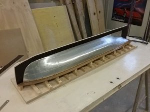
First longitudinal flanges for deck and half hull were made of MDF to be able to separate the mold halves from each another:
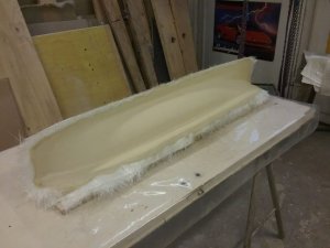
First half of mold laminated:
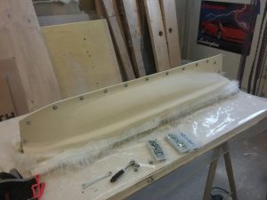
Both halves laminated and bolted together:
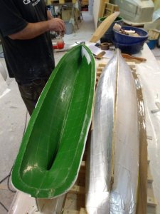
Mold completed and separated from the original hull. Some aluminum plates didn`t resist the chemicals used and came off the original hull. This had however no effect on the surface of the mold:
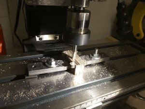
In the mean time building of steam engine continued. This time machining of the cylinder block was made. First the upper and lower surfaces were smoothed:
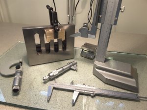
All holes were carefully marked and those for upright columns were drilled:
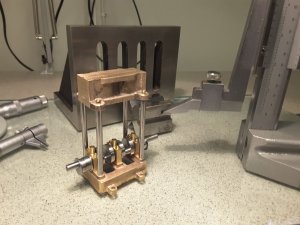
Cylinder block attached to the columns with M3 nuts:
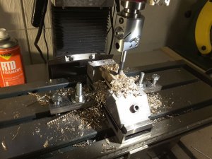
Cylinders were first bored in the milling machine:
And finalized & smoothed in the lathe:
As I told earlier the hull was sent to a professional glassfibre shop for making a mold of it, and laminate three final hulls for all of us. The idea was that rows of rivets would be copied into the mold and could be seen on the surfaces of final hulls. That succeeded completely, and it was nice to receive nicely made hulls from the shop for further building.
First longitudinal flanges for deck and half hull were made of MDF to be able to separate the mold halves from each another:

First half of mold laminated:

Both halves laminated and bolted together:

Mold completed and separated from the original hull. Some aluminum plates didn`t resist the chemicals used and came off the original hull. This had however no effect on the surface of the mold:

In the mean time building of steam engine continued. This time machining of the cylinder block was made. First the upper and lower surfaces were smoothed:

All holes were carefully marked and those for upright columns were drilled:

Cylinder block attached to the columns with M3 nuts:

Cylinders were first bored in the milling machine:

And finalized & smoothed in the lathe:

Great progress and very interesting photos you are sharing with us.
We can see that the mold is really fully showing the plating and nailing pattern - it is looking very good !

You ordered three hulls, do I understood it correctly? - So it is a "group-built"?
Does it mean that in some time we can see three Lempis steaming in Finland?
We can see that the mold is really fully showing the plating and nailing pattern - it is looking very good !
You ordered three hulls, do I understood it correctly? - So it is a "group-built"?
Does it mean that in some time we can see three Lempis steaming in Finland?
Thanks Uwe. You are right, we are a group of three people each building his own Lempi. But I am afraid that I am the only one of us writing here, so you don't see other logs that mine here. Also I am the only one of us trying to build a steam engine for the boat, all others have bought their engines.
However you are very welcome to see all of them steaming here in some beautiful lake sometimes during the summer.
However you are very welcome to see all of them steaming here in some beautiful lake sometimes during the summer.
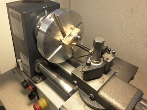
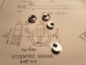
During laminating of the hulls at glassfibre shop I had time to concentrate into steam engine building. Next I made the eccentric sheaves to drive the slide valves. There are no castings for these, and the plan suggests them to be made out of mild steel. Eccentricity is according to plan 3/32" which corresponds 2,38 millimeters. Of course the eccentric sheaves could have been made in the lathe using 4 jaw chuck, but I had read somewhere that it is also possible in 3 jaw, to insert a suitable packing between the workpiece and one of the jaws. According to given formula, the packing P could be calculated: P=1,5 x offset. So P=1,5 x 2,38mm which results to 3,57 mm. I machined a small piece of brass into this thickness, inserted it between the workpiece and one jaw and started drilling and turning. And very soon I got four eccentric sheaves with about 2,4 mm eccentricity, near enough for me.
Workpiece drilled with a packing under one jaw:
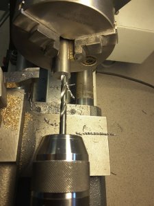
Eccentric sheaves drilled and turned:
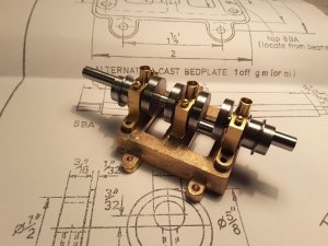
And installed on the cranckshaft. Each sheave is locked on its place with a M2 grub screw giving the possibility for timing the engine.
Workpiece drilled with a packing under one jaw:

Eccentric sheaves drilled and turned:

And installed on the cranckshaft. Each sheave is locked on its place with a M2 grub screw giving the possibility for timing the engine.

Superb skills, Moxis!
Next item to make were the cylinder heads. Nice gunmetal castings were provided for them, so it was straight forward just to tighten them in the 3 jaw chuck and start turning. Holes for bolts were drilled in the milling machine using rotary table, and threaded holes at cylinder block located after the heads. Holes had to be drilled very carefully, not to break a tiny 1,7 mm drill bit inside the cylinder block. Threads used are M2.
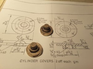
Castings provided for cylinder heads:
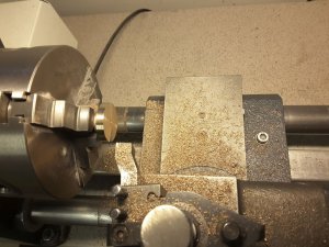
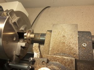
Turning process started:
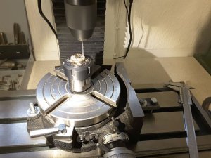
Drilling the holes for bolts using a rotary table in milling machine:
Cylinder heads ready. Bolts are M2:
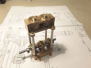
Castings provided for cylinder heads:

Turning process started:


Drilling the holes for bolts using a rotary table in milling machine:

Cylinder heads ready. Bolts are M2:

Thanks Knut. There is nothing wrong with woodworking. I have seen fabulous ships and carvings made of wood entirely with hand tools. In fact I envy that kind of skills which I still want to learn.
But this time into metalwork. The next thing to do are the cylinder covers under the block. They must be made very carefully, because the piston rod is going through them, and there is also a tiny threaded piston rod gland which tightens the rod into the cover. Straight forward turning and threading work. Graphited yarn is used as packing around the piston rod later when the engine is installed.
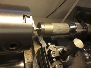
Threading the piston rod gland in the lathe using a very convenient die holder. The drawing suggests 1/4"x40 thread, but I don't have a die & tap for this so I was using metric fine thread M5x0,5 instead:
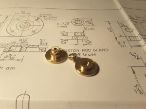
Cylinder covers underneath the block with piston rod glands:
But this time into metalwork. The next thing to do are the cylinder covers under the block. They must be made very carefully, because the piston rod is going through them, and there is also a tiny threaded piston rod gland which tightens the rod into the cover. Straight forward turning and threading work. Graphited yarn is used as packing around the piston rod later when the engine is installed.
Threading the piston rod gland in the lathe using a very convenient die holder. The drawing suggests 1/4"x40 thread, but I don't have a die & tap for this so I was using metric fine thread M5x0,5 instead:

Cylinder covers underneath the block with piston rod glands:

Last edited:
Next a bit more demanding operation: To make the trunk guides which control the movement of crossheads and pistons. Very careful machining is necessary because all the parts must move easily together without too much play.
A nice gunmetal casting is provided for them, of which both trunk guides must be made.
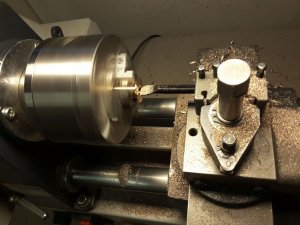
Surfacing and cleaning the casting in lathe:
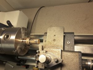
Outside turned into correct dimensions. Here both trunk guides are still together:
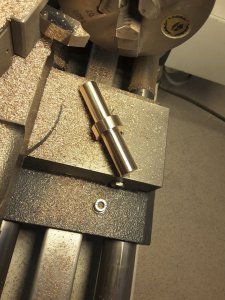
Trunk guides separated from each other and boring going on. Very accurate turning is necessary, because crosshead is moving inside the trunk guide and together with the piston must move easily and without too much play:
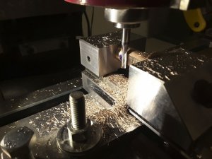
Side openings machined in the milling machine:
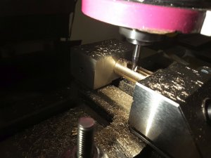
Side openings opened and edges cleaned:
Test installation of underside cylinder covers and trunk guides. Bolts are again M2:
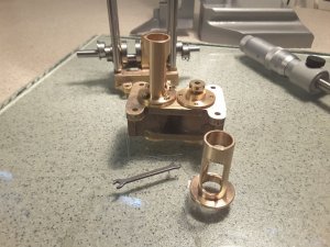
And finally our engine starts to look like a steam engine. Steam passages at the cylinder block are still missing, because they are very filigrane, and I had to order a 1 mm milling cutter to be able to machine them:
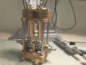
A nice gunmetal casting is provided for them, of which both trunk guides must be made.
Surfacing and cleaning the casting in lathe:

Outside turned into correct dimensions. Here both trunk guides are still together:

Trunk guides separated from each other and boring going on. Very accurate turning is necessary, because crosshead is moving inside the trunk guide and together with the piston must move easily and without too much play:

Side openings machined in the milling machine:

Side openings opened and edges cleaned:

Test installation of underside cylinder covers and trunk guides. Bolts are again M2:

And finally our engine starts to look like a steam engine. Steam passages at the cylinder block are still missing, because they are very filigrane, and I had to order a 1 mm milling cutter to be able to machine them:

- Joined
- Jun 19, 2013
- Messages
- 968
- Points
- 393

My Oh My...wonderful machining skills and fantastic work you are doing. Love it all.
I've machined plenty of parts...but never a steam engine.
Following with much enjoyment.
Rob
I've machined plenty of parts...but never a steam engine.
Following with much enjoyment.
Rob
There were no castings provided for the connecting rods, so everything had to be made of stock materials: Brass flat and round silver steel rod.
Cones for connecting rods were first turned from pieces of silver steel:
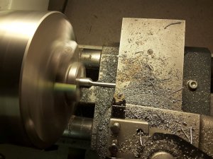
Then suitable pieces for big ends were cut out of brass flat bar with slitting saw attached into milling machine spindle:
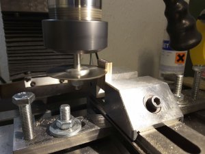
Those were then drilled and tapped for M2 bolts:
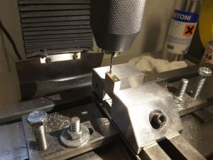
And bored in the lathe 4 jaw chuck:
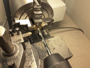
A small piece of mild steel was attached into the big end for screwing the coned part into it. Connection was secured with thread locking compound. And then the big end was turned into its final shape using a mandrel:
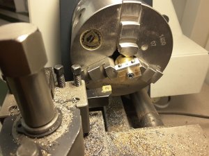
Finally the small end was turned and a hole drilled for crosshead pin:
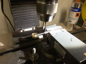
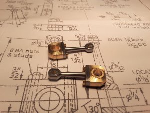
A small brass bush was pressed into the small end hole, and after a few hours work the connecting rods were ready:
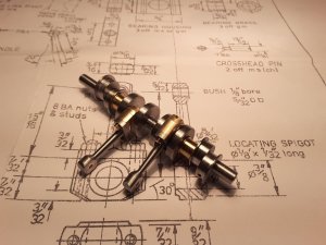
Installed into cranckshaft:
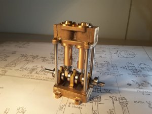
And installed into engine. At first they were a bit stiff and hardly rotated, but after adding some grinding paste and carefully rotating the crankshaft it started to turn smoothly:
Cones for connecting rods were first turned from pieces of silver steel:

Then suitable pieces for big ends were cut out of brass flat bar with slitting saw attached into milling machine spindle:

Those were then drilled and tapped for M2 bolts:

And bored in the lathe 4 jaw chuck:

A small piece of mild steel was attached into the big end for screwing the coned part into it. Connection was secured with thread locking compound. And then the big end was turned into its final shape using a mandrel:

Finally the small end was turned and a hole drilled for crosshead pin:

A small brass bush was pressed into the small end hole, and after a few hours work the connecting rods were ready:

Installed into cranckshaft:

And installed into engine. At first they were a bit stiff and hardly rotated, but after adding some grinding paste and carefully rotating the crankshaft it started to turn smoothly:

I am speechless. What workmanship! What a delight to watch! Bravo, Moti!
Simply GREAT work 


Thank you Jim and Uwe. When I started this log I thought that nobody would be interested about building of a marine steam engine. In the beginning it seemed to be so, no comments, no likes were received, and I thought to remove the complete log from here.
But luckily it seems that somebody of you are interested, of which I am very glad. There is not very much work any more left to get the engine ready and running, so I hope your interest will last until then.
And after that, when I get the hull from glassfibre shop it begins to be interesting again to see how I am able to fit the engine and boiler into the boat hull.
I am looking forward to seeing how is your Lempi coming together, maybe you can ask the other two Lempi builders and borrow some images from them to show us their Lempis.
...and to add to Zoly's comment. They might be interested in joining our friendly family of SOSes?I am looking forward to see how is your Lempi coming together,maybe you can ask the other two Lempi builder and borrow som images from them to show us their Lempis.


